Difference between revisions of "S24: Team Falcons"
(→Hardware Design) |
(→Hardware Design) |
||
| Line 326: | Line 326: | ||
=== Hardware Design === | === Hardware Design === | ||
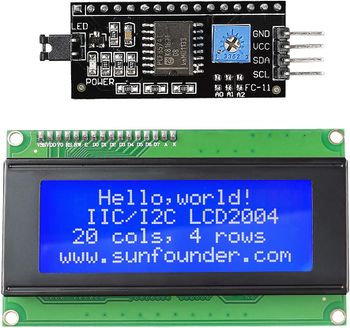
| − | Driver node gives the interconnection between input and output. It receives input from geo node and sensor node and give commands to the motor node. The only hardware driver has is the LCD display and CAN transceiver. The LCD display used is a SunFounder IIC I2C TWI Serial 2004 20x4 LCD Module and is interfaced through an I2C bus through the I2C2 port. The pin connections for LCD is shown below. | + | Driver node gives the interconnection between input and output. It receives input from geo node and sensor node and give commands to the motor node. The only hardware driver has is the LCD display and CAN transceiver. The LCD display used is a SunFounder IIC I2C TWI Serial 2004 20x4 LCD Module and is interfaced through an I2C bus through the I2C2 port. The module used and pin connections for LCD is shown below. |
| − | [[File:LCD Module.jpg|350px| | + | [[File:LCD Module.jpg|350px|left|thumb|Master controller Hardware Design]] |
{| style="margin-left: auto; margin-right: auto; border: none;" | {| style="margin-left: auto; margin-right: auto; border: none;" | ||
Revision as of 23:35, 17 May 2024
Contents
Project Title
Falcons
Abstract
<2-3 sentence abstract>
Introduction
The project was divided into N modules:
- Sensor ...
- Motor..
- ...
- Android
Team Members & Responsibilities
<Team Picture>
Gitlab Project Link - [1]
<Provide ECU names and members responsible> <One member may participate in more than one ECU>
- Sensor
- Link to Gitlab user1
- Link to Gitlab user2
- Motor
- Link to Gitlab user1
- Link to Gitlab user2
- Geographical
- Link to Gitlab user1
- Link to Gitlab user2
- Communication Bridge Controller & LCD
- Link to Gitlab user1
- Link to Gitlab user2
- Android Application
- Link to Gitlab user1
- Link to Gitlab user2
- Testing Team
- Link to Gitlab user1
- Link to Gitlab user2
Schedule
| Week# | Start Date | End Date | Task | Status |
|---|---|---|---|---|
| 1 | 02/22/2024 | 02/26/2024 |
|
Completed |
| 2 | 02/26/2024 | 03/10/2024 |
|
Completed |
| 3 | 03/10/2024 | 03/12/2024 |
|
Not completed |
| 4 | 03/12/2024 | 03/19/2024 |
|
Not completed |
| 5 | 03/19/2024 | 03/26/2024 |
|
Not completed |
| 6 | 03/26/2024 | 04/02/2024 |
|
Not completed |
| 7 | 04/02/2024 | 04/09/2024 |
|
Not completed |
| 8 | 04/09/2024 | 04/16/2024 |
|
Not completed |
| 9 | 04/16/2024 | 04/23/2024 |
|
Not completed |
| 10 | 04/23/2024 | 04/30/2024 |
|
Not completed |
| 11 | 04/30/2024 | 05/07/2024 |
|
Not completed |
Parts List & Cost
| Item# | Part Desciption | Vendor | Qty | Cost |
|---|---|---|---|---|
| 1 | RC Car | Traxxas | 1 | $250.00 |
| 2 | CAN Transceivers MCP2551-I/P | Microchip [2] | 8 | Free Samples |
Printed Circuit Board
<Picture and information, including links to your PCB>
CAN Communication
<Talk about your message IDs or communication strategy, such as periodic transmission, MIA management etc.>
Hardware Design
<Show your CAN bus hardware design>
DBC File
<Gitlab link to your DBC file> <You can optionally use an inline image>
Sensor ECU
<Picture and link to Gitlab>
Hardware Design
Software Design
<List the code modules that are being called periodically.>
Technical Challenges
< List of problems and their detailed resolutions>
Motor ECU
<Picture and link to Gitlab>
Hardware Design
Software Design
<List the code modules that are being called periodically.>
Technical Challenges
< List of problems and their detailed resolutions>
Geographical Controller
<Picture and link to Gitlab>
Hardware Design
Software Design
<List the code modules that are being called periodically.>
Technical Challenges
< List of problems and their detailed resolutions>
Communication Bridge Controller & LCD
<Picture and link to Gitlab>
Hardware Design
Software Design
<List the code modules that are being called periodically.>
Technical Challenges
< List of problems and their detailed resolutions>
Driver Node
Gitlab Link: https://gitlab.com/jincyjose491/sjtwo-c/-/tree/master/projects/driver?ref_type=heads
<Picture>
Hardware Design
Driver node gives the interconnection between input and output. It receives input from geo node and sensor node and give commands to the motor node. The only hardware driver has is the LCD display and CAN transceiver. The LCD display used is a SunFounder IIC I2C TWI Serial 2004 20x4 LCD Module and is interfaced through an I2C bus through the I2C2 port. The module used and pin connections for LCD is shown below.
|
Software Design
<List the code modules that are being called periodically.>
Technical Challenges
< List of problems and their detailed resolutions>
Mobile Application
<Picture and link to Gitlab>
Hardware Design
Software Design
<List the code modules that are being called periodically.>
Technical Challenges
< List of problems and their detailed resolutions>
Conclusion
<Organized summary of the project>
<What did you learn?>
Project Video
Project Source Code
Advise for Future Students
<Bullet points and discussion>
