Difference between revisions of "F15: Autonomous Mobile"
Proj user19 (talk | contribs) (→Schedule) |
Proj user19 (talk | contribs) (→Hardware Components) |
||
| Line 147: | Line 147: | ||
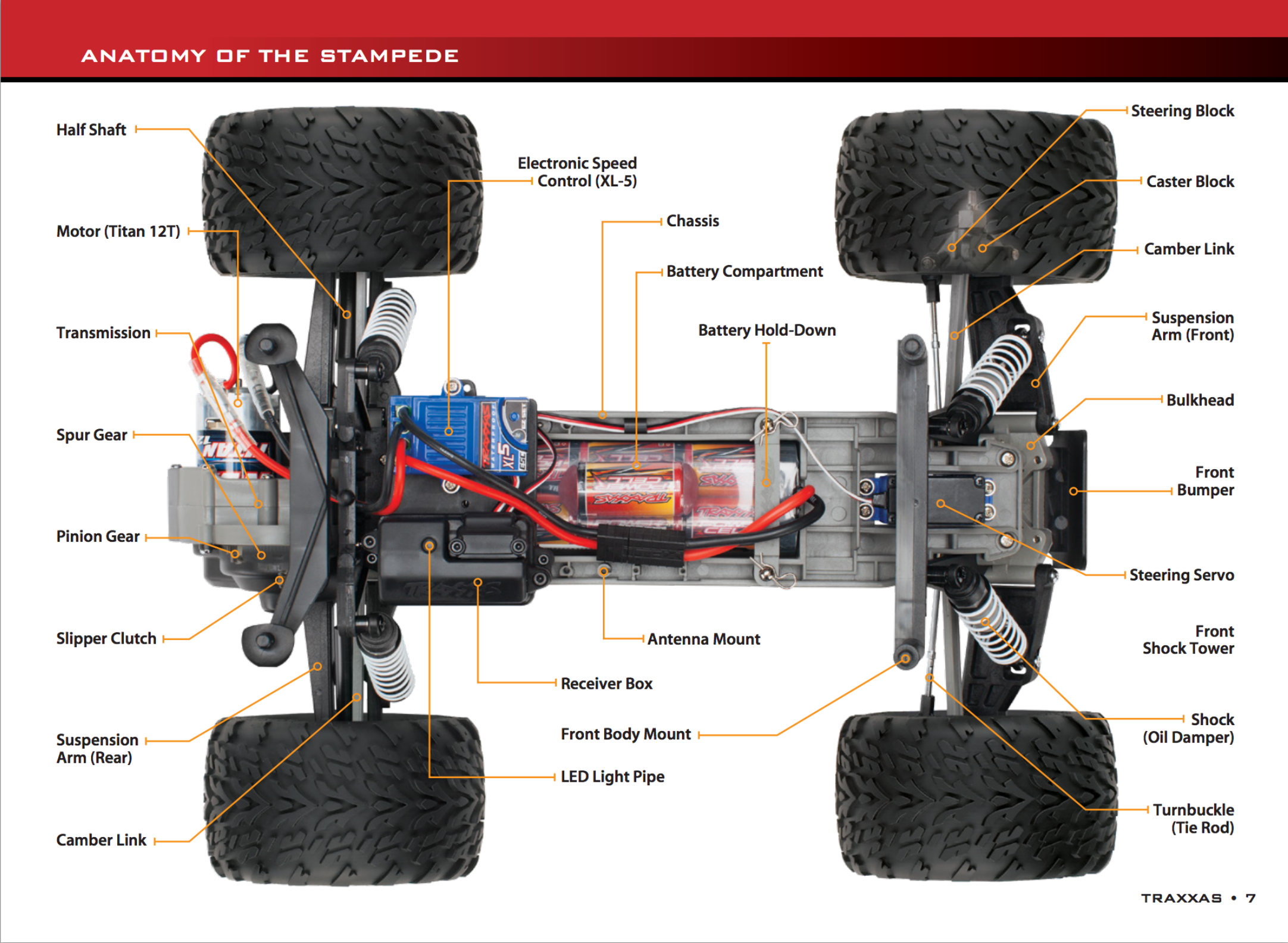
'''Traxxas 36054-1 Stampede: Monster Truck''' | '''Traxxas 36054-1 Stampede: Monster Truck''' | ||
<br> | <br> | ||
| − | + | [[File:Cmpe146_F15_AutoMobile_carStructure.png]] | |
Revision as of 23:27, 16 December 2015
Contents
Abstract
Tesla Motors just announced their own developed technology on the October 14, 2015 - Autopilot on all of their currently supporting vehicle Model S. Using some of the top-of-the-line industrial sensor - a forward radar, a forward-looking camera, 12 long-range ultrasonic sensors, and a high-precision digitally-controlled electric assist braking system, an automated driving capabilities luxury car is being delivered. All of those feedback modules were being involved differently in the autopilot system. With a similar concept on the self-driving capability model RC car, our team is going to deliver similar technology with the knowledge on different peripheral drivers.
Objectives & Introduction
This program is target to deliver a self-driving vehicle with GPS/compass module and bluetooth communication with Android. Obstacle avoidance will only be added if time is permitted. The below are the tasks we aim to deliver: Motor and Servo, GPS, Compass, and Bluetooth enable.
Team Members & Responsibilities
- Kenneth Chiu
- B.S. Computer Engineering
- Yuyu Chen
- B.S. Computer Engineering
Schedule
The point of the schedule is for readers to assess how to pace themselves if they are doing a similar project.
| Week# | Start Date | End Date | Task | Status | Completion Date |
|---|---|---|---|---|---|
| 1 | 10/16/2015 | 10/22/2015 | Idea confirm, order project parts | Completed | 10/22/2015 |
| 2 | 10/23/2015 | 10/29/2015 | Start building Android App, connect motor controller, test motor & servo | Completed | 10/28/2015 |
| 3 | 10/30/2015 | 11/05/2015 | Get Compass, GPS, and Bluetooth modules working (implement drivers to output raw data) | Completed | 11/05/2015 |
| 4 | 11/06/2015 | 11/12/2015 | Calibrate Compass and Parse GPS data (get useful data) | Completed | 11/20/2015 |
| 5 | 11/13/2015 | 11/19/2015 | Integrate Compass and GPS together (heading, bearing, distance) | Completed | 11/29/2015 |
| 6 | 11/20/2015 | 11/26/2015 | Continue working on Integration of Compass and GPS algorithm | Completed | 11/29/2015 |
| 7 | 11/27/2015 | 12/03/2015 | Integrate motor with Geographical unit | Completed | 11/29/2015 |
| 8 | 12/04/2015 | 12/10/2015 | Test Autonomous car, work on Bluetooth integration | Completed | 12/16/2015 |
| 9 | 12/11/2015 | 12/17/2015 | Test Autonomous car | Completed | 12/16/2015 |
Parts List & Cost
| Qty | Description | Manufacturer | Part Number | Total Cost | Links |
|---|---|---|---|---|---|
| 1 | SJ One Board [1] | Preet | SJ-one | $80 | http://www.socialledge.com/sjsu/index.php?title=SJ_One_Board |
| 1 | Traxxas Stampede: Monster Truck [2] | Traxxas | 36054-1 | $199.95 | http://www.amazon.com/Traxxas-36054-1-Stampede-Monster-Ready-To-Race/dp/B00OK3AJWW/ref=zg_bs_166587011_6 |
| 1 | GPS Bee kit (with Mini Embedded Antenna) [3] | Adafruit | MTK3339 | $39.95 | http://www.adafruit.com/products/746 |
| 1 | Triple Axis Compass Magnetometer Sensor Module [4] | Adafruit | HMC5883L | $9.95 | http://www.adafruit.com/products/1746 |
| 1 | BTBee Pro Bluetooth XBee Wireless Module [5] | ITEAD Studio | BR010292 | $14.99 | https://www.bananarobotics.com/shop/BTBee-Pro-Bluetooth-XBee-Wireless-Module |
Design & Implementation
The design section can go over your hardware and software design. Organize this section using sub-sections that go over your design and implementation.
Hardware Design
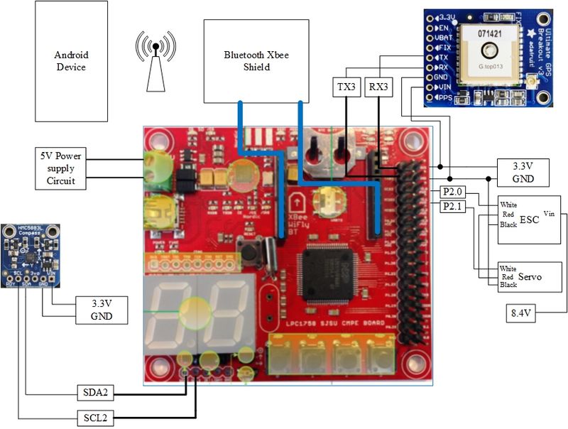
Discuss your hardware design here. Show detailed schematics, and the interface here.
Hardware Components
Traxxas 36054-1 Stampede: Monster Truck

BTBee Pro Bluetooth XBee
ken
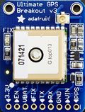
MTK3339 Ultimate GPS
The MTK3339 Ultimate GPS module from Adafruit was chosen because it provides us with more than enough functionalities. All we needed from the GPS module was the longitude and latitude from raw NMEA sentence.
It provides an accuracy of 5-10 meters (or worse if indoors) with its 22 satellites transmitting data to the GPS module. An external antenna can be attached to improve accuracy. The GPS module can be interfaced to a micro controller through UART interface with a default baud rate of 9600. It can be powered on with 3.3V-5VDC, which can be provided from the SJOne board. It provides an LED indicator that blinks at about 1Hz while searching for satellites and blinks once every 15 seconds when a fix is found to conserve power. The GPS module will allow us to calculate the bearing and destination from its current GPS coordinate and the destination coordinate.

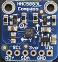
HMC5883L Triple Axis Compass Magnetometer
The HMC5883L Triple-axis Magnetometer module from Adafruit was chosen because it provides us with heading relative to magnetic north.
Most importantly, it allows us to steer toward our destination. The magnetometer has 6 data registers that can be read from which contains the 8 bit MSB or LSB x,y,z coordinates. Although the z-axis is provided, it is not used but can be useful in future projects. The magnetometer sensor uses I2C interface to communicate with a microcontroller. It can be powered on with either 3V-5VDC. There is also a Ready pin that can be used to speed up reading the data registers.

Hardware Interface
In this section, you can describe how your hardware communicates, such as which BUSes used. You can discuss your driver implementation here, such that the Software Design section is isolated to talk about high level workings rather than inner working of your project.
Traxxas 36054-1 Stampede: Monster Truck
ken
BTBee Pro Bluetooth XBee
ken
MTK3339 Ultimate GPS
yc
HMC5883L Triple Axis Compass Magnetometer
yc
Software Design
Show your software design. For example, if you are designing an MP3 Player, show the tasks that you are using, and what they are doing at a high level. Do not show the details of the code. For example, do not show exact code, but you may show psuedocode and fragments of code. Keep in mind that you are showing DESIGN of your software, not the inner workings of it.
Implementation
This section includes implementation, but again, not the details, just the high level. For example, you can list the steps it takes to communicate over a sensor, or the steps needed to write a page of memory onto SPI Flash. You can include sub-sections for each of your component implementation.
Testing & Technical Challenges
Describe the challenges of your project. What advise would you give yourself or someone else if your project can be started from scratch again? Make a smooth transition to testing section and described what it took to test your project.
Include sub-sections that list out a problem and solution, such as:
My Issue #1
Issue: Calibration of 3-axis magnetometer
Need to calibrate compass because center is not at origin. Huge error of 20-30 degrees. Hard iron cause shift in x,y axis. Soft iron distort shape of circle into an ellipse. Need to keep compass on a flat surface because a tilt will affect x,y values
Resolution:
Calibration was applied by subtracting the hard-iron offsets. Heading error reduced to range of 0-10 degrees. Ignoring soft-iron distortion because value is not constant and changes with location.
My Issue #2
Issue:
Resolution:
Conclusion
Conclude your project here. You can recap your testing and problems. You should address the "so what" part here to indicate what you ultimately learnt from this project. How has this project increased your knowledge?
Project Video
Motor and Servo: https://youtu.be/AdKw1G4GNOM
Motor and Servo (updated): https://youtu.be/y9YGl9JmKUU
Geographical Unit integration with motor (compass only): https://www.youtube.com/watch?v=N3GIjYgyP60
Self Driving Field Test 1: https://www.youtube.com/watch?v=R7_ALVbJFRE
Self Driving Field Test 2: https://www.youtube.com/watch?v=9BRb-uHcNx4
Project Source Code
References
Acknowledgement
Android application: https://github.com/kennethchiu22/AndroBluetooth
Compass sensor: https://learn.adafruit.com/downloads/pdf/adafruit-hmc5883l-breakout-triple-axis-magnetometer-compass-sensor.pdf
Motor and Servo: http://www.socialledge.com/sjsu/index.php?title=SJ_One_Board#Motor_.26_Servo_Control
References
[1] http://www.socialledge.com/sjsu/images/d/de/2012SJOneBoardSchematic.pdf
[2] https://traxxas.com/sites/default/files/24054-36054-37054-OM-N-EN-R02_0.pdf
[3] http://www.adafruit.com/datasheets/GlobalTop-FGPMMOPA6H-Datasheet-V0A.pdf
[4] http://www.adafruit.com/datasheets/HMC5883L_3-Axis_Digital_Compass_IC.pdf
[5] ftp://imall.iteadstudio.com/Modules/IM121115002_BTBeepro/DS_IM121115002_BTBeepro.pdf
Grading Criteria
- How well is Software & Hardware Design described?
- How well can this report be used to reproduce this project?
- Code Quality
- Overall Report Quality:
- Software Block Diagrams
- Hardware Block Diagrams
- Schematic Quality
- Quality of technical challenges and solutions adopted.
