Difference between revisions of "S13: Smart Cube"
(→System Schematic) |
(→Wifly Wifi Module RN-XV) |
||
| Line 261: | Line 261: | ||
(As discussed in the software implementation section) | (As discussed in the software implementation section) | ||
| − | Note that this wifi module is listed here because it's a hardware component; however, its implementation is on the software side. | + | Note that this wifi module is listed here because it's a hardware component; however, its implementation is on the software side. It's connected to the XBee port on the LPC board. |
Revision as of 06:24, 20 May 2013
Contents
- 1 Grading Criteria
- 2 Smart CUBE
- 3 Abstract
- 4 Objectives & Introduction
- 5 Parts List & Costs
- 6 Design & Implementation
- 7 Testing & Technical Challenges
- 8 Conclusion
- 9 References
Grading Criteria
- How well is Software & Hardware Design described?
- How well can this report be used to reproduce this project?
- Code Quality
- Overall Report Quality:
- Software Block Diagrams
- Hardware Block Diagrams
- Schematic Quality
- Quality of technical challenges and solutions adopted.
Smart CUBE
Abstract
This section should be a couple lines to describe what your project does.
Objectives & Introduction
Team Members & Responsibilities
- Phuoc Tran
- Interface LPC1758 with 8x8 RGB LED matrix using shift registers
- Christopher Harris
- Interface LPC1758 with WiFly module, server to WiFly communication and Website UI.
| Week | Planned Tasks | Achievement |
|---|---|---|
| |
|
|
| |
|
|
| |
|
|
| |
|
|
| |
|
|
| |
|
|
Parts List & Costs
| Item | Details | Source | Cost Ea. | Qty. | Total |
|---|---|---|---|---|---|
| MicroController | LPC 1758 SJSU Dev Board | Preet | $60.00 | x1 | $60.00 |
| Wifi Module | RN-XV Wifly | Sparkfun | $37.99 | x1 | $37.99 |
| RGB LED Display | 8x8 RGB LED Matrix | Ebay | $5.99 | x1 | $5.99 |
| Shift Register | SN74HC595 | Sparkfun | $0.23 | x3 | $.69 |
| Wire | Female -> Female Jumper wire | Sparkfun | $0.28 | x50 | 14.39 |
| Wire | 30 Gauge Wrapping wire | Anchor | $5.00 | x1 | $5.00 |
| Prototyping board | 6"x6" Perforated Prototyping board | Anchor | $6.99 | x1 | $6.99 |
| IC Socket | Socket IC 16 Pin | Anchor | $.37 | x6 | $2.25 |
| Resistors | 220 Ohm 1/4 Resistor | Anchor | $.06 | x32 | $1.92 |
| Linux Server | Raspberry Pi | Ebay | $35.00 | x1 | $35.00 |
| Wireless Router | Ti Link 703N Mini Router | Frys | $24.00 | x1 | $24.00 |
Design & Implementation
Hardware Design
The main hardware components used in this project include:
- LPC1758 Development Board
- 8x8 RGB LED matrix
- 74HC595 Shift Register
- Buzzer
- Wifly Module
LPC1758 Development Board
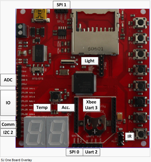
It is the CPU of the project. It communicates with devices or transfers communications between devices to perform tasks. The LPC1758 dev board is running under SJSU development package. The package contains most of drivers necessary for the CPU to communicate with devices such as SPI interface, PWM motor controller.
8x8 RGB LED matrix
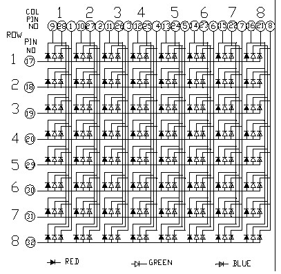
The figure below is the schematic of an 8x8 RGB LED matrix. It has the size of 60 mm square, and it contains 8 anode terminals and 24 cathode terminals in a total of 192 LEDs. 64 of the LEDs are red, 64 are Green, and the other 64 are Blue. The purpose and use of this LED matrix is very important in this cube because it is the main output of the project. It will display the real time time clock, alarm and email notifications, and temperature.
74HC595 Shift Register
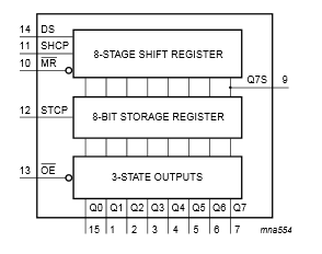
The purpose of the shift register in this project to take the serial inputs from the CPU and convert to both parallel outputs and serial outputs. Parallel outputs is use to turn on and off the LEDs. Serial outputs is used to feed into another shift register if applicable.
Buzzer
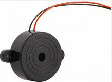
A buzzer is used for alarm of email notifications. It will sound to notify that the alarm is on or someone just got a mail.
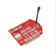
Wifly Wifi Module RN-XV
(As discussed in the software implementation section)
Note that this wifi module is listed here because it's a hardware component; however, its implementation is on the software side. It's connected to the XBee port on the LPC board.
System Building Block
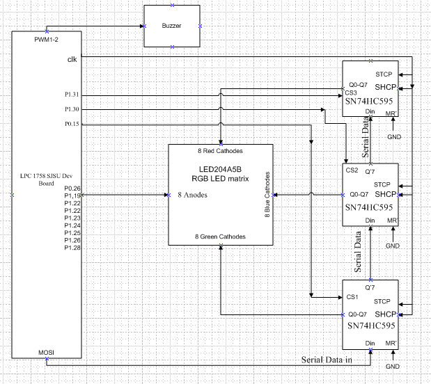
Figure 1 shows the block diagram of the whole circuit. It shows the basic idea of how all the devices or part are connected as well as their inputs and outputs.
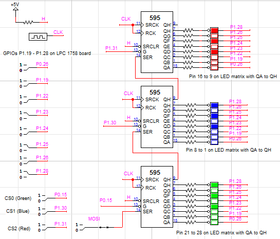
System Schematic Among CPU, Shift Registers, and LED matrix
Figure 2 demonstrates more detail of circuit implementation. The circuit was built and tested on Logic Works. It shows the interface among the LPC board, LED matrix, and 3 shift registers. The red, green, and blue LEDs represents the corresponding ones of the RGB LED matrix. All Px.x pins (outputs), CLK, and MOSI are generated from the LPC 1758 board. The binary switches are used to test the behavior of the circuit when switching the output pins from high to low or vice versa.
Hardware Interface
SPI Interface
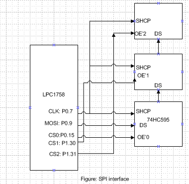
In the SPI interface figure, CLK is pin P0.7, MOSI is pin P0.9, and CS0,CS1,CS2 are P0.15,P1.30, and P1.31. CLK is the output to shift registers. Master Out Slave In (MOSI) is used to send serial data (one Byte at a time) to the first shift register along with clk. Serial outputs from the first register will feed to the next register and so on. CS0, CS1, CS2 are used to control parallel outputs of shift registers.
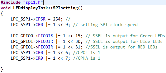
Below is the figure of how to initialize and set SPI driver for SSP1
An "spi.h" header file is used for SSP1 driver.
Because peripheral clk (PCLK) is a high speed clock(48Mhz), we need to slow it down so that SPI devices such shift registers can operate efficiently. The SPI clock speed equation is PCLK / (CPSDVSR × [SCR+1]) with PCLK being 48Mhz.
"LPC_SSP1->CPSR = 254" is to set CPSDVSR equal to 254 since CPSDVSR is an 8-bit register. "LPC_SSP1->CR0 |= (1 << 9)" is to set SCR bits to 1(default is 0). The last two lines in the SPI setting are used for clock polarity (CPOL) and clock phase (CPHA).
To send data to shift register and output data, a function "spi1_ExchangeByte(data)" in "spi.h" is call where data size is one byte. After the first call, a byte of data will be sent to the first shift register.If the CPU continues to send data, each byte of data will be shift to the next register and so on. It the CPU stops sending data, the last bytes, depending on number of shift register used, will be held at the outputs of these shift registers. Now, the CPU will generate control signals to output those data.
PWM
LED matrix Interface
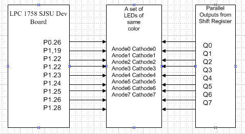
The figure on the right is showing how to interface with a single set of LEDs of the same color. The strategy of LED matrix interface is to control to which LEDs along with which colors (green, red, blue) to be on or off. Each LED has 2 terminals, one is Anode(+) and one is Cathode(-). All the LEDs of the same row sharing the same Anode terminal, but different Cathode terminals. There are 8 Anode terminals controlled by the outputs of GPIO pins as in the figure on the right. There are 24 Cathode terminals, where every 8 of these Cathode terminals (of the same color) are controlled by the parallel outputs of a shift register. In order to turn on which LEDs, a control signal(CS) will select which shift register to be output. Meanwhile, outputs from GPIO pins to rows will turn on LEDs at desired locations.
For example, according the figure of LED matrix interface, if PO.26 is high and output Q0 is low, then the first LED will be on. If P0.26 is high but Q0 is high also, the first LED will be off.
Software Design
In designing our Smart Cube we first identified the main software features of our system and how we should control them. The main features of the smart cube are the wifi communication, and the LED display. With these main features we then delegated the features into manageable tasks that would control and implement these features.
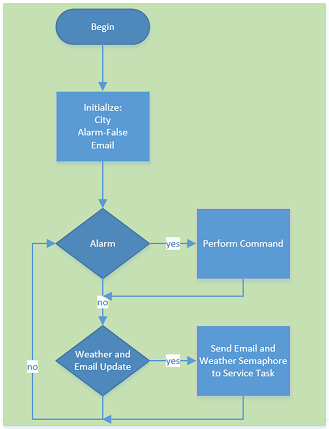
The Data Task is responsible for triggering the Alarm, sending the email and weather semaphores and initializing the global variables. This task is run in a medium priority in order to preserve other smart cube features; the LED display and the wifi service task.
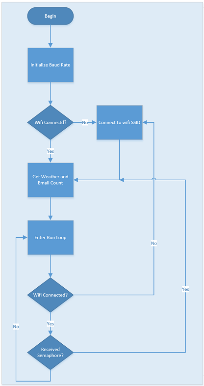
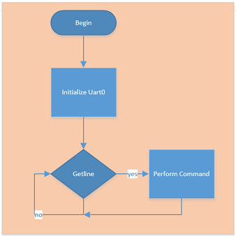
The Service Task is responsible for managing the Wifi. This includes initializing the WiFly module, checking wifi connectivity, and retrieving the weather and email counts when the semaphore is received. The block diagram for this is shown in figure 2.
The terminal task is the basic terminal task provided in the SJSU Dev package. It is responsible for managing both UART1 and UART3, our usb and wifi data bus’s. This task allows us to issue commands from the website, or phone application as well as debug using Hercules terminal. The block diagram from the terminal task is shown in Figure 3.
Hardware Implementation
Software Implementation
FreeRTOS
The basis for our software implementation required using FreeRTOS, a real-time operating system. FreeRTOS, which is provided in the SJSU Developer package for the LPC1758, utilizes C and C++. It allows for the implementation of task, semaphores and queues, all of which are managed by the operating system. The previous labs, as well as the tutorials available on the Social Ledge website served as a reference for our design and implementation.
8x8 Matrix
WiFly
The management of the Wi-Fly and wifi connectivity was done in the services task. This task was responsible for initializing the Wi-Fly with the appropriate values and connecting to the defined SSID. With the Wi-Fly connected to a SSID it was the service task responsibility to ensure that a connection was established and maintained. With a connection obtained the Wi-fly module could access the smart cube website and receive data as a tcp client and server.
The pseudo code for connecting to a SSID and enabling the WiFly module as both a tcp client and server is as follows:
//Set connection parameters
Enable dhcp
Define the ssid
Define the protection type (wep, wpa, etc..)
Define pw
Define channel
Define mask

//Set communication parameters
define close
define open
define remote

//Set flush parameters
set comm size
set timeout length
set idle time

//Set TCP paramters
set to client and server(variable “2”)
define port number

Save
Reboot
Get Weather
In order to obtain the weather the smart cube acted as a tcp client utilizing the World Weather Online api at (api.worldweatheronline.com). Using this api we were able to configure the wi-fly module to request the weather in a http 1.0 format. In order to do so the Wi-Fly must act in TCP Client mode, connect to the source ip, and perform a “get” to retrieve the data desired. An example of getting the weather from the api is shown below:
wifiSendCmd("open api.worldweatheronline.com 80");

mWifi.put("GET http://api.worldweatheronline.com/free/v1/weather.ashx?q=CITYformat=csv&num_of_days=1&key=API-KEY HTTP/1.1");
From this http response we were able to parse the data looking for the temperature. The example format of the http response not including the header is as shown below:
#The CSV format is in following way:-
#First row will always contain the current weather condition. if for any reason we do not have current condition it will have 'Not Available'.
#The current weather condition data is laid in the following way:-
 #observation_time,temp_C,weatherCode,weatherIconUrl,weatherDesc,windspeedMiles,windspeedKmph,winddirDegree,winddirPoint,
precipMM,humidity,visibility,pressure,cloudcover
 #
#The weather information is available in following format:
#date,tempMaxC,tempMaxF,tempMinC,tempMinF,windspeedMiles,windspeedKmph,winddirDegree,winddir16Point,weatherCode,
weatherIconUrl,weatherDesc,precipMM
#
05:04 AM,15,113,http://www.worldweatheronline.com/images/wsymbols01_png_64/wsymbol_0008_clear_sky_night.png,Clear,11,17,
320,NW,0.0,63,16,1018,0,2013-05-15,21,70,11,52,13,21,320,NW,113,
http://www.worldweatheronline.com/images/wsymbols01_png_64/wsymbol_0001_sunny.png,Sunny,0.0
The data can be obtained in various formats, including CSV, JSON, and XML. In our usage we found CSV the easiest format to parse, as we could easily traverse through the response using the “,” as our delimiter.
Get Email Count
Similarly to retrieving the weather, the process of obtaining the email count was done simply by accessing the getemail.php file that is hosted on the server. The first step in obtaining the email count is connecting to the server as a tcp client. Then the url can be sent with the appropriate php parameters in the url. The process of connecting and obtaining the email count is shown below:
wifiSendCmd("open SERVER-IP 80");

mWifi.put("GET http://SERVER-IP/getemail.php?username=USERNAME&pass=PASSWORD HTTP/1.1");
Web Server
The hosting of our webserver was done on a Raspberry Pi. Since we spend a significant amount of time developing at school, we found that connecting to a remote server with the Wi-fly module was nearly impossible since the SJSU wifi would not release an IP. In order to resolve this we turned to using a local webserver to satisfy our testing and development needs.
The Raspberry Pi was setup with the standard rasbian “wheezy” linux distro, which can be found here: http://www.raspberrypi.org/downloads . With the distro setup and an active Internet connection the Apache and PHP server could then be installed. In order to do so, the following commands were issued to the command line (NOTE: this can be done over SSH as well).
sudo apt-get install -y rpi-update

sudo apt-get update -y && sudo apt-get upgrade –y
Now your raspberry pi is up to date and you can proceede with installing apache and setting up the appropriate permissions.
sudo apt-get install -y apache2 apache2-utils

sudo groupadd -f -g33 www-data

sudo chown pi:www-data /var/www

sudo chmod 775 /var/www
Lastly you will need to install PHP and curl this is done with the following command:
sudo apt-get install -y php5 libapache2-mod-php5 php5-common mysql-client

sudo apt-get install -y php-pear php5-mysql php5-curl php5-gd php5-idn php5-imagick
php5-imap php5-mcrypt php5-memcache php5-mhash php5-ming php5-ps php5-pspell
php5-recode php5-snmp php5-sqlite php5-tidy php5-xmlrpc php5-xsl php5-json
Now is a good time to reboot the raspberry pi with the following command:
sudo reboot
Once the raspberry pi is fully booted you can test to see if Apache and PHP were successfully installed. To do so, create a file called test.php in the vars/www/ folder and add the phpinfo(); function, as shown below:
sudo nano /vars/www/test.php

//add text

<?php phpinfo(); ?>
If the php information shows on your screen when you navigate to: www.RAPBERRYPI-IP/test.php then you successfully configured your raspberry pi as a webserver.
Web Interface
In order to send commands to the smart cube in an efficient and intuitive way a user interface was needed. Ideally an interface or solution that did not require installing a program or additional software on the users end. For this reason we utilized the already existing wireless features of our system to send commands from a website. The website functions included:
- Setting the Alarm Time
- Setting the City of the Weather
- Defining the GMAIL Credentials
- Setting the Time Interval
- Future Features
Front End
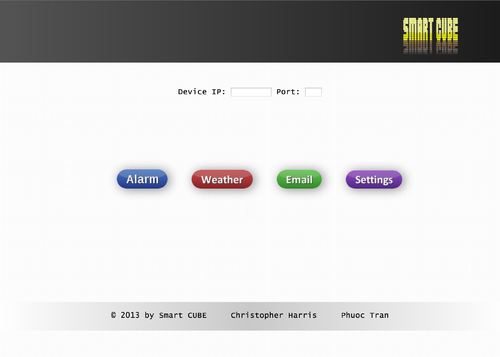
The Front End of Web interface involved utilizing HTML, in conjunction with JavaScript to display and send data using JQUERY and AJAX to the back end. In designing the front end of the website our goal was simplicity and ease of navigation. In order to do so we utilized large interactive, self-intuitive buttons, and an IFrame to focus on pertinent information. Our implementation was all done by hand, using notepad++ and Filezilla as our ftp client. The buttons on our layout were obtained from http://dabuttonfactory.com, a neat tool that allows for the creation of custom buttons. The first image shows the home page, utilizing the large self intuitive buttons.
In order to send data to the back end of the server for processing, we utilized the JQUERY JavaScript plugin to post data to a PHP file. The PHP file could then analyze the data and perform the necessary functions as discussed in the next section. It is important to note, unlike other coding languages, Javascript is event driven. That is functions and operations are performed and when a specific event is triggered, such as a button click. One such example of an event driven function in javascript is the showing and removing of a button shadow when a cursor hovers over a button. Some sample code for this is shown below:
$(".Shadow").hover(
      function() {
          $(this).attr("style", "box-shadow: none;");
      },
       function() {
          $(this).attr("style", "box-shadow: 0px 2px 22px #4B91A5;");
       }
);
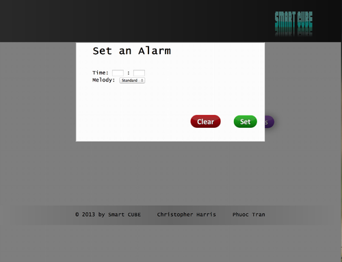
Note: this utilizes JQUERY which is denoted by the “$” identifier before the event function. This code is typically placed in the “OnLoad” portion of the javascript file. This image shows the result of pressing the alarm button, opening the alarm.html page in an IFrame.
Back End
The back end of the web interface implemented using PHP on a Linux Apache Server. We chose Linux because it was readily available on our development computers and we could deploy a mobile server using a raspberry pi. The back end PHP functions of our server consisted of:
- Sending commands to the Wi-fly module via a TCP Connection
- Set Alarm
- Set City for Weather
- Send Email Count
- Setting the Time Interval for Weather and Email Notifications
- Retrieving the email count from a RSS Gmail feed
Sending Commands to the Wi-Fly Module
In order to communicate to the board the server needed to send commands regarding the users action on the webpage. These commands included:
- Alarm set HH MM
- Alarm clear
- Weather set CITYNAME
- Email set USERNAME PASSWORD
- Fetch set HOUR
The triggering of these commands is done when a user navigates to the various pages and submits data. When data is submitted on the webpage a jquery event is triggered and data is posted to the appropriate php file using ajax. The post contains the “action” or function to be called, and the various parameters needed in the command. When sending a command to the Wi-Fly module the server acts as a tcp client and connects to the wi-fly module at the designated ip and port 5555. Once connected the tcp client can send its desired information and the smart-cube will treat the information just as it would a command given over Uart-0.
Getting Email Count
The first set in attempting to obtain the email count on our server was creating a PHP file that would be called from the Wi-Fly board every time the Smart Cube requested the email count. This PHP’s file’s purpose was, with the given parameters, call its internal “get email” function. The parameters are passed to the PHP function in the url in the following format:
www.smartcube.com/getemail.php?param1=value1¶m2=value2
The parameters used in our case were just the email id and the email password. With this information PHP’s cURL utility in conjunction with Google’s atom feed would be able to retrieve the desired information.
In order to obtain the email count from google’s “atom” feed, the cURL library was used. cURL on in a primitive description is like a internet browser without the UI. It allows for a PHP to create a session and access webpages data in html format. For the purpose of collecting the email count of a Gmail account curl was used to create a secure connection to https://mail.google.com/mail/feed/atom. Once a oAuth connection was made data would be retrieved in a xml format similar to this:
       "<?xml version="1.0" encoding="UTF-8"?>
       <feed version="0.3" xmlns="http://purl.org/atom/ns#">
       <title>Gmail - Inbox for BLAHH@gmail.com</title>
       <tagline>New messages in your Gmail Inbox</tagline>
       <fullcount>100</fullcount>
       <link rel="alternate" href="http://mail.google.com/mail" type="text/html" />
       <modified>2013-5-12T12:33:48Z</modified>
       <entry>
       <title>Blahhh EMAIL</title>
       <summary>This is some sample summary text!!</summary>
       <link rel="alternate" href="http://mail.google.com/mail
       account_id=BLAHH@gmail.com&message_id=123456&view=conv&extsrc=atom" type="text/html" />
       <modified>2012-5-12T12:12:44Z</modified>
       <issued>2012-5-12T12:12:44Z</issued>
       <id>tag:gmail.google.com,2004:1234567890</id>
       <author>
       <name>BLAHH Author</name>
       <email>FROM_EMAIL@Blahh.com</email>
       </author>
       </entry>
       <entry>"
The next part would be to parse the xml data looking only for the email count in our case. By accessing the xml tag “fullcount”, as a SimpleXMLElement, we were able to parse the response for the current unread email count.
More information regarding cURL and its used in PHP can be found here: http://php.net/manual/en/book.curl.php
Windows Phone 8 Application
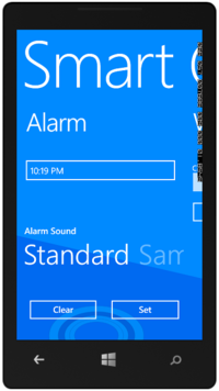
The purpose of the Windows Phone 8 Application was to provide another convenient interface for communicating to the Smart Cube. The communication method to the Smart Cube from the WP8 application is done through TCP/IP. By utilizing TCP/IP we did not need to reinvent the implementation of communicating to the Smart Cube. Rather with TCP/IP we were able to access the smart cube just as we did with the PHP services. Creating an application to connect to a TCP socket was very easy, considering the wealth of information available on the Internet.
By utilizing the following article, which discusses setting up a TCP application, we were able to integrate all the desired features of our existing website into a mobile application. http://msdn.microsoft.com/en-us/library/windowsphone/develop/hh202858(v=vs.105).aspx
The WP8 application opens up requesting the IP and Port number of the Wi-Fly device, an attempt is then made to connect to the board. The process for connecting to the wi-fly module from the windows phone application was done by following the previously mentioned tutorial. This tutorial began by setting up the SocketClient Class, with a connect function, and send data function. The basics of this class included utilizing the innate .NET TCP stream and DNS endpoint libraries. With these libraries a socket connection can easily be made and with supporting functions data can be sent to a tcp server.
Testing & Technical Challenges
Describe the challenges of your project. What advise would you give yourself or someone else if your project can be started from scratch again? Make a smooth transition to testing section and described what it took to test your project.
Include sub-sections that list out a problem and solution, such as:
Wifi Connection Issues
Many wifi connection issues were encountered. To solve this problem, a dedicated task was created to re-connect to wifi if the connection was ever lost.
Conclusion
Conclude your project here. You can recap your testing and problems. You should address the "so what" part here to indicate what you ultimately learnt from this project. How has this project increased your knowledge?
Project Video
Project Source Code
Send me your zipped source code and I will upload this to SourceForge and link it for you.
References
Acknowledgement
Dr. Haluk Özemek
Preet Kang
References Used
List any references used in project.
Appendix
You can list the references you used.
