Difference between revisions of "S17: Halo"
Proj user10 (talk | contribs) (→Objectives & Introduction) |
Proj user10 (talk | contribs) (→Team Members & Responsibilities) |
||
| Line 46: | Line 46: | ||
** | ** | ||
* Revathy | * Revathy | ||
| − | ** | + | ** Design hardware and software for warning system |
| + | ** Develop application Algorithm | ||
| + | ** Build hardware circuit | ||
| + | ** Integrate the functionality to the main project | ||
| + | ** Unit testing, verification, and validation of the module | ||
* Unnikrishnan | * Unnikrishnan | ||
** | ** | ||
Revision as of 13:40, 21 May 2017
Contents
Grading Criteria
- How well is Software & Hardware Design described?
- How well can this report be used to reproduce this project?
- Code Quality
- Overall Report Quality:
- Software Block Diagrams
- Hardware Block Diagrams
- Schematic Quality
- Quality of technical challenges and solutions adopted.
Halo: The Smart Helmet
Abstract
This project aims to improve the safety of bicycle users on busy roads. Often, it is difficult for drivers in cars to judge the movement of a bicyclist on the road. This problem becomes significant in scenarios where the driver has to follow the bicyclist in dark environments. We propose Halo, a smart helmet which makes bicyclists feel safe and stand out on busy roads thus improving their safety.
Objectives & Introduction
We propose to build a simple yet, powerful system that helps improve the safety of bicyclists on busy roads. The sensors used to build this system are the accelerometer and the ultra-sound sensor. Our objective to was to complete all the functionalities listed below
- Designing of Motion Analysis Engine
- Recording of the accelerometer readings from bicyclists in real time
- Understanding and interpreting the accelerometer readings
- Designing an algorithm to detect motion/slow down/stop in real time.
- Designing of the warning system
- Record data from ultrasound sensors in real time
- Set thresholds to trigger state transitions
- Wireless interface
- Indicator system
- PCB design
- Blah blah...
- Interfacing all functionalities using freeRTOS APIs
Team Members & Responsibilities
- Abhay Prasad
- Revathy
- Design hardware and software for warning system
- Develop application Algorithm
- Build hardware circuit
- Integrate the functionality to the main project
- Unit testing, verification, and validation of the module
- Unnikrishnan
- Vishalkumar
- Kripanand Jha
Schedule
This section of the report provides the team schedule for the Halo Smart Helmet project, indicating the milestones to be achieved during the course of the project.
| Week# | Date | Task | Actual |
|---|---|---|---|
| 1 | 03/21 | Team Discussion on understanding and finalizing requirements; Identify extra hardware requirements | Completed |
| 2 | 03/28 | Design Hardware and Software modules;Finalize on schematic; Purchase h/w components. | Completed |
| 3 | 04/04 | Interface Accelerometer & Ultrasound sensors; Finalise API layer for individual modules | Completed |
| 4 | 04/11 | Implement modules - start/stop detect algo,distance detect algo,Wireless comm,LED-Display Pane | Completed |
| 5 | 04/18 | Interface system with wireless modules; PCB design | Completed |
| 6 | 04/25 | SW & HW unit testing | Completed |
| 7 | 05/02 | System level Integration & testing | Planned |
| 8 | 05/09 | OnRoad testing /Blackbox testing | Planned |
| 9 | 05/16 | Project Demo | Planned |
Parts List & Cost
| Parts# | Part Name | Quantity | Cost Unit Item |
|---|---|---|---|
| 1 | Bike | 1 | Free |
| 2 | Helmet | 1 | Free |
| 3 | 9 V DC battery | 4 | 3.00 $ |
| 4 | Wireless Antenna | 2 | 2.20 $ |
| 5 | SJOne Board | 2 | 80 $ |
| 6 | PCB fabrication | 10 | 2.8 $ |
Design & Implementation
Printed Circuit Board
Design
We designed custom 28.2 x 48.8 mm board for our project. The goal of the PCB design was to learn the basics of PCB designing using EAGLE software as it is one of the part of embedded systems. We have added two switches along with two leds for showing left right direction while turning the bike. We added connectors on the board to further connect the switch to external board and also connect the power and ground to the external circuit.
EAGLE Software
To design our board we used AUTODESK EAGLE application. We designed schematics and PCB for our board in EAGLE. This board will be interfaced with SJOne board's gpio, power and GND pin. For the schematic design we used SparkFun library components like switches, leds, connector, resistors. After done with schematics, EAGLE generates board design based on schematics we create. In board design it's on you how you minimize the board space place your components in the board. After done with proper design we can either opt for auto-routing or manual routing thing to route the various components in the board. While routing, use proper values of width and drill size for the route. After done with routing check for any errors in the board connections using ERC and DRC tools. We designed dual layer pcb just for the sake of testing. for the common ground we used ground polygon that makes circuit design simpler. While routing note down the drill size and width of traces it must be sufficient enough to for current flow in the wire.
EAGLE components used
| Parts# | Part Name | DEVICE | LIBRARY | PACKAGE |
|---|---|---|---|---|
| 1 | LED | LED-3MM-NO_SILK (LED) | SparkFun-LED | LED_3MM-NS |
| 2 | SWITCH | MOMENTARY-SWITCH-SPST-PTH-6.0MM (MOMENTARY-SWITCH-SPST) | SparkFun-Switches | TACTILE_SWITCH_PTH_6.0MM |
| 3 | Connectors | CONN_04 | SparkFun-Connectors | 1X04 |
| 4 | Capacitors | 0.1UF-KIT-EZ-50V-20% (0.1UF) | SparkFun-Capacitors | CAP-PTH-SMALL-KIT |
Algorithm Design
Designing the algorithm to detect the state of the cyclist was approached by first recording the data from the accelerometer sensor as the cyclist rides it in a real time environment. The recording for three different cyclists for 10 minutes at 10KHz was done. Each of these recordings made sure to cover all test cases that the system would encounter in real time. An in-sync video of the cyclist riding the bike was recorded in order to serve as the ground truth for evaluating the designed algorithm.
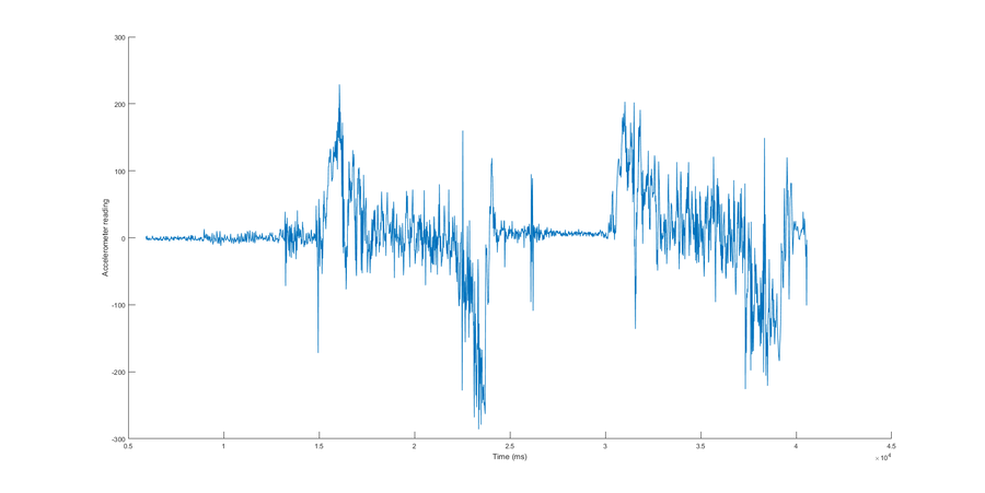
We have used Matlab to prototype the algorithm from the accelerometer readings. The logged data from the cyclists shows the kind of response we obtain for different situations encountered by the cyclist. Below is the plot of the accelerometer readings for a cyclist. As you can see, the high level of noise present in the signal makes it very hard to interpret the state of the cyclist at different time instants.
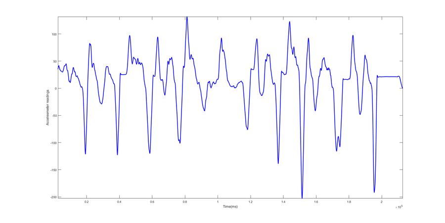
In order to eliminate noise from the accelerometer values, a moving averaging filter of length 100 was used. The plot of the values in Matlab after performing this simple type of filtering is shown below. It is easy to interpret the regions where the cyclist is in motion. Whenever the accelerometer readings peak and settle (comes back to the settling point and becomes constant), the cyclist can be interpreted to be in motion. We can observe a dip in the graph as soon as the cyclist slows down or comes to a stop. The difference between a slowdown and a stop is hard to interpret looking at the accelerometer readings. After carefully evaluating the signal and comparing it to the ground truths, we were able to finally find a solution to distinguish between the two. A very interesting observation is that there is always a slight deceleration after a stop during the settling of the signal which is not present during slowdowns. This is due to the nature of the breaking system on any vehicle. We have exploited this concept to distinguish a slowdown from a stop.
It is obvious that a stop is always after a slowdown and there is no slowdown after a stop. Concepts such as these have motivated us to implement a state machine as a part of the algorithm. The figure below shows the state machine that we implemented with the help of Matlab. In order to make the algorithm robust to any user, we have tried our best to minimize hard thresholds for state transitions.
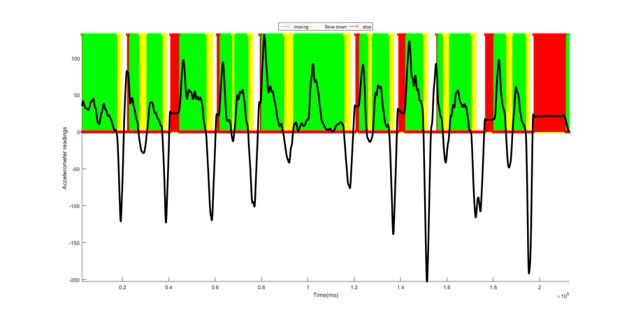
The figure below shows the result of the state machine prototyped in Matlab. The regions in green correspond to the cyclist in motion and the ones in yellow and red are the regions for slow down and stop respectively.
The designed algorithm in Matlab was ported to C++ to work on the SJOne board. The moving averaging filter was designed to work in real time as shown in the snippet below. The state transitions code is similar to that of the Matlab code.
The calibration phase is performed during booting and is important to zero offset the values of the accelerometer. This was done as we found the range of the accelerometer readings to vary when using different boards. During calibration, the cyclist is expected to stay in the stopped state for 3 seconds before starting. The mean of these value is considered to be the offset. The calibration offset is now subtracted from the values obtained from the accelerometer in real time to determine the state of the cyclist.
Hardware Design
Discuss your hardware design here. Show detailed schematics, and the interface here.
Hardware Interface
In this section, you can describe how your hardware communicates, such as which BUSes used. You can discuss your driver implementation here, such that the Software Design section is isolated to talk about high level workings rather than inner working of your project.
Software Design
Show your software design. For example, if you are designing an MP3 Player, show the tasks that you are using, and what they are doing at a high level. Do not show the details of the code. For example, do not show exact code, but you may show psuedocode and fragments of code. Keep in mind that you are showing DESIGN of your software, not the inner workings of it.
Implementation
This section includes implementation, but again, not the details, just the high level. For example, you can list the steps it takes to communicate over a sensor, or the steps needed to write a page of memory onto SPI Flash. You can include sub-sections for each of your component implementation.
Testing & Technical Challenges
Describe the challenges of your project. What advise would you give yourself or someone else if your project can be started from scratch again? Make a smooth transition to testing section and described what it took to test your project.
Include sub-sections that list out a problem and solution, such as:
My Issue #1
Discuss the issue and resolution.
My Issue #2
Discuss the issue and resolution.
My Issue #3
Discuss the issue and resolution.
My Issue #4
Discuss the issue and resolution.
Conclusion
We successfully completed implementing all the proposed objectives.
Project Video
Video coming soon....
Project Source Code
Surce code coming soon...
References
Acknowledgement
Any acknowledgement that you may wish to provide can be included here.
References Used
List any references used in project.
Appendix
You can list the references you used.


