Difference between revisions of "S17: ElectricBoard"
Proj user15 (talk | contribs) (→Conclusion) |
Proj user15 (talk | contribs) (→Team Members & Key Responsibilities) |
||
| (73 intermediate revisions by 2 users not shown) | |||
| Line 1: | Line 1: | ||
| − | === | + | == Abstract == |
| − | |||
| − | |||
| − | |||
| − | |||
| − | |||
| − | |||
| − | |||
| − | |||
| − | |||
| − | |||
| − | |||
| − | |||
| − | |||
Transportation is a necessary part of everyday life, and it can be a stressful, time-consuming task. People are often looking for faster, cleaner, inexpensive, and more convenient modes for transportation. Considering the amount of traffic in urban areas such as San Jose, regular vehicles are not as convenient or quicker than other methods such as bikes or skateboards. However, cities like SJ are quite large college cities, so human-powered modes make it potentially tiring. Therefore, this project hopes to enhance these modes by creating electronic versions. | Transportation is a necessary part of everyday life, and it can be a stressful, time-consuming task. People are often looking for faster, cleaner, inexpensive, and more convenient modes for transportation. Considering the amount of traffic in urban areas such as San Jose, regular vehicles are not as convenient or quicker than other methods such as bikes or skateboards. However, cities like SJ are quite large college cities, so human-powered modes make it potentially tiring. Therefore, this project hopes to enhance these modes by creating electronic versions. | ||
| Line 27: | Line 14: | ||
* Establish wireless communication between motor control and remote control systems | * Establish wireless communication between motor control and remote control systems | ||
| − | === Team Members & Responsibilities === | + | === Team Members & Key Responsibilities === |
* Andrew Vo | * Andrew Vo | ||
| − | ** | + | ** Motor control and receiver code framework |
| + | ** Hardware schematics | ||
* Elton Leung | * Elton Leung | ||
| − | ** | + | ** Incorporation of wireless API |
| + | ** Hardware Assembly/Design | ||
* Eric Panganiban | * Eric Panganiban | ||
| − | ** | + | ** Software Framework |
| + | ** Remote control Implementation | ||
| + | ** Motor Control Implementation | ||
| + | ** Wireless Implementation | ||
| + | ** Driver Implementation | ||
| + | ** Interface to ESC | ||
* James Grantham | * James Grantham | ||
| − | ** | + | ** LCD interface + drawing framework |
| + | ** PCB layout | ||
* Saketh Sai Narayana | * Saketh Sai Narayana | ||
| − | ** | + | ** PCB assembly |
| + | ** Hardware assembly | ||
== Schedule == | == Schedule == | ||
| − | |||
{| class="wikitable" | {| class="wikitable" | ||
|- | |- | ||
| Line 49: | Line 44: | ||
! scope="col"| Status | ! scope="col"| Status | ||
! scope="col"| Details | ! scope="col"| Details | ||
| − | ! scope="col"| | + | ! scope="col"| Completed on: |
|- | |- | ||
! scope="row"| 0 | ! scope="row"| 0 | ||
| Line 97: | Line 92: | ||
| Remote Control Implementation | | Remote Control Implementation | ||
| Completed | | Completed | ||
| − | | Using pin | + | | Using pin 0.0 for button and pin 0.26 for analog slider. Screen to be implemented later. |
| 04/25/2017 | | 04/25/2017 | ||
|- | |- | ||
| Line 110: | Line 105: | ||
| 05/09 | | 05/09 | ||
| Fine Tune | | Fine Tune | ||
| − | | | + | | Completed |
| − | | | + | | Antennas added to improve wireless communication. Lowered max duty cycle. Pressure sensor added. LCD screen implemented. |
| − | | | + | |05/16/2017 |
|- | |- | ||
! scope="row"| 9 | ! scope="row"| 9 | ||
| 05/16 | | 05/16 | ||
| Prepare for Demo/Complete Report | | Prepare for Demo/Complete Report | ||
| − | | | + | | Completed |
| − | | | + | | Completed. |
| − | + | | 05/23/2017 | |
|- | |- | ||
! scope="row"| 10 | ! scope="row"| 10 | ||
| 05/23 | | 05/23 | ||
| Project Demo | | Project Demo | ||
| − | | | + | | Completed |
| − | | | + | | Project Demo in E337 at 6:00PM |
| − | | | + | | 05/25/2017 |
|} | |} | ||
| − | + | == Parts List & Cost == | |
| − | |||
| − | |||
{| class="wikitable" | {| class="wikitable" | ||
|- | |- | ||
| Line 194: | Line 187: | ||
| 1 | | 1 | ||
| UI display for remote control | | UI display for remote control | ||
| + | |- | ||
| + | |- | ||
| + | ! scope="row"| Antenna | ||
| + | | $8.99 | ||
| + | | 2 | ||
| + | | Improve wireless communication range | ||
|- | |- | ||
|} | |} | ||
| − | |||
== Design & Implementation == | == Design & Implementation == | ||
| − | |||
| − | |||
=== Hardware Design === | === Hardware Design === | ||
| − | |||
There are two subsystems to consider for hardware design: the motor controller and the remote control. | There are two subsystems to consider for hardware design: the motor controller and the remote control. | ||
| Line 219: | Line 214: | ||
| − | [[File:CMPE244_S17_MotorControlDiagram.png | 700px | thumb | center| Skateboard Top Level Connection]] | + | [[File:CMPE244_S17_MotorControlDiagram.png | 700px | thumb | center| '''Figure 1: Skateboard Top Level Connection''']] |
| + | |||
| + | |||
| + | [[File:CMPE244 S17 SkateBoardView.jpg | 700px | thumb | center | '''Figure 2: View of Skateboard''' ]] | ||
===== Remote Control ===== | ===== Remote Control ===== | ||
| Line 231: | Line 229: | ||
* TFT LCD Screen | * TFT LCD Screen | ||
| − | + | The remote control also uses an SJ One Board as the main micro controller. The slider switch, buttons and LCD Screens are all connected directly to the SJ One Board on the header pins on the right hand side, with respective resistors for the switch and button. Further details of which pins and functions are detailed in the Remote Control of the Hardware Interface below. The printed PCB will connect to the green portion noted as the "Battery Power" on the SJ One Board diagram on the main page. The remote control can be seen below: | |
| + | |||
| + | |||
| + | [[File:CMPE244_S17_ElectricBoard_RemoteControlView.jpg |500px | thumb | center| '''Figure 3: View of Remote Control''']] | ||
| − | [[File:CMPE244_S17_RemoteTopLevel.png | 300px | thumb | center | Remote Top Level Connection]] | + | [[File:CMPE244_S17_RemoteTopLevel.png | 300px | thumb | center | '''Figure 4: Remote Top Level Connection''']] |
=== Hardware Interface === | === Hardware Interface === | ||
| − | |||
| − | ===== | + | The tables below show which pins and what functions are used for the external components such as switches and buttons. However, they can be changed as long as the functions are consistent with what is needed. |
| + | |||
| + | ===== Motor Controller ===== | ||
{| class="wikitable" | {| class="wikitable" | ||
| Line 257: | Line 259: | ||
|} | |} | ||
| + | For this project, Pin 2.0 was used to output a PWM signal to the ESC's. The ESC then sends an AC signal to drive the motors depending on the characteristics of the PWM signal. Pin 0.1 was used as a normal GPIO pin to receive input from the force sensor. We chose not to use one of the ADC pins on the board because we only care if there is a person on the board or not. We did not need to determine exactly how much force is applied to the force sensor. | ||
| − | + | [[File:CMPE244_S17_BoardCircuit.png | 400px | thumb | center | '''Figure 5: Skateboard Circuit''']] | |
| − | [[File:CMPE244_S17_BoardCircuit.png | 400px | thumb | center | Skateboard Circuit]] | ||
===== Remote Control ===== | ===== Remote Control ===== | ||
| Line 281: | Line 283: | ||
| TFT LCD Screen Display | | TFT LCD Screen Display | ||
|- | |- | ||
| − | ! scope="row"| P1.28-P.31 | + | ! scope="row"| P1.23, P1.28-P.31 |
| GPIO | | GPIO | ||
| TFT LCD Screen Controls | | TFT LCD Screen Controls | ||
|} | |} | ||
| − | The main components used for the remote control were a slider switch, a button, and a TFT LCD Screen for UI. The slider switch is an analog signal, which requires an ADC pin to be used for the input. The button can be a GPIO, which will read when the switch is activated. The TFT LCD Screen uses pins 0-7 on port 2 for the display, and pins 28-31 and pin | + | The main components used for the remote control were a slider switch, a button, and a TFT LCD Screen for UI. The slider switch is an analog signal, which requires an ADC pin to be used for the input. The ADC pin is already configured during startup. Pin 0.26 was chosen as it is oneo of the pins that support ADC input. The button can be a GPIO, which will read when the switch is activated. Pin 0.0 was configured to be a GPIO pin to receive input for the switch. The TFT LCD Screen uses pins 0-7 on port 2 for the display, and pins 28-31 and pin 23 on port 1 for the control signals. Use of this LCD screen requires these pins to be configured as GPIO pins. |
| − | ====== Interface ====== | + | ====== General Remote Interface ====== |
| − | The slider switch is used to control the speed of the skateboard by varying resistance in the circuit. The button would be used to initiate that speed that is sent to the skateboard. The speed can only be changed once the button is being held. If the button is not held, the speed will default back to zero. This methodology was use was to limit communication between the boards, and thus, lower power consumption as well. For this instance, an ADC pin and a GPIO pin were needed for both the slider switch and the button, respectively. A diagram of the connections can be seen in the Figure below: | + | The slider switch is used to control the speed of the skateboard by varying resistance in the circuit. The button would be used to initiate that speed that is sent to the skateboard. The speed can only be changed once the button is being held. If the button is not held, the speed will default back to zero. This methodology was use was to limit communication between the boards, and thus, lower power consumption as well. For this instance, an ADC pin and a GPIO pin were needed for both the slider switch and the button, respectively. A diagram of the connections can be seen in the Figure below: |
| − | [[File:CMPE244_S17_RemoteControlDiagram.png | 500px | thumb | center | Remote Circuit]] | + | [[File:CMPE244_S17_RemoteControlDiagram.png | 500px | thumb | center | '''Figure 6: Remote Circuit''']] |
| − | Once the button is pressed, it would activate an interrupt, which would immediately send the signal of the slider into a queue to communicate with the SJ One Board on the skateboard to control the motors. To send the information via wireless communication, the nordic wireless API ("wireless.h") was used. This is a wrap-around for "mesh.h". | + | Once the button is pressed, it would activate an interrupt, which would immediately send the signal of the slider into a queue to communicate with the SJ One Board on the skateboard to control the motors. To send the information via wireless communication, the nordic wireless API ("wireless.h") was used. This is a wrap-around for "mesh.h". |
| − | + | An LCD is driven by the SJone board to provide visual feedback on the board's wireless connection and speed information among others. It is controlled via an 8 bit data bus on pins P2.0 to P0.7 and 5 control pins on P1.31 to P1.28 and P1.23 for Reset, Chip Select, Write Mode, Read Mode, and Command/Data switching. The driver code it adapted from and AVR driver built for Arduino. The following figure shows the working LCD screen with the parameters given from the skateboard. The eBrake status is shown at the top, battery on the top right, connection status (Conn: ), operation time (Op. Time: ), acceleration, and power level. | |
| − | - | + | |
| + | [[File:CMPE244_S17_ElectricBoard_LCD_Screen_Display.png | 500px | thumb | center | '''Figure 7: LCD Screen Display''']] | ||
| + | |||
| + | |||
| + | |||
| + | The designed PCB is a simple system to take the voltage provided from a small Lithium Ion battery (3.2-3.7 range) and upscale it to the necessary input voltage of the SJone board of 5 volts. The 5V and Gnd connections attach to the corresponding input connectors on the board to provide power to it and the accompanying LCD screen. | ||
| + | |||
| + | |||
| + | [[File:CMPE244_S17_ElectricSkateboard_PCB_Schematic.png |500px | thumb | center | '''Figure 8: PCB Schematic''' ]] | ||
| + | |||
| + | |||
| + | [[File:CMPE244_S17_ElectricSkateboard_PCB_Layout.png|500px | thumb | center | '''Figure 9: PCB Layout''']] | ||
=== Software Design === | === Software Design === | ||
Show your software design. For example, if you are designing an MP3 Player, show the tasks that you are using, and what they are doing at a high level. Do not show the details of the code. For example, do not show exact code, but you may show psuedocode and fragments of code. Keep in mind that you are showing DESIGN of your software, not the inner workings of it. | Show your software design. For example, if you are designing an MP3 Player, show the tasks that you are using, and what they are doing at a high level. Do not show the details of the code. For example, do not show exact code, but you may show psuedocode and fragments of code. Keep in mind that you are showing DESIGN of your software, not the inner workings of it. | ||
| − | There are ''' | + | |
| − | RemoteControl continuously checks to see if the button is pressed. If | + | There are '''5''' main tasks that runs this project: '''RemoteUI''', '''RemoteControl''', '''ElectricBoardSender''', '''ElectricBoardReceiver''', and '''ElectricBoardControl'''. |
| + | |||
| + | |||
| + | The '''RemoteUI''' is used to display the information on the TFT LCD screen. It gets data from ElectricBoardSender. It obtains information in the form of OnScreenData struct. The OnScreenData struct is in OnScreenData.hpp, and is given by 5 parameters: bool connectionStatus, int eBrakeActive, int powerLevel, float batteryLevel, and int accelerometer. ConnectionStatus is the indicator to show if the remote control still has connection to the skateboards. It will frequently send messages and waits for the reply to see a connection still exists. The eBrakeActive is an indicator for the force sensor, the powerLevel for the speed of the skateboard, battery Level for the battery left in the remote, and accelerometer for the acceleration of the entire skateboard. The acceleration uses the instances of the SJ One board using AS.getX(); | ||
| + | |||
| + | |||
| + | '''RemoteControl''' initializes the interrupts using eint3_enable_port0(), creates semaphores for buttonSignal, and creates screenQueue for OnScreenData struct. This function continuously checks to see if the button on the remote Control is pressed. If it is pressed, it will calculate powerLevel by getting the result of input divided by MAX_READ and multiplying it by 100. After calculating the powerLevel, it will send the data using sendPowerLevel() which uses the wireless API wireless_send() to electricBoardReceiver. If the button is not pressed, it will send a 0 for powerLevel. | ||
| + | |||
| + | |||
| + | '''ElectricBoardSender''' specifically sends information such as acceleration and the pressure to the RemoteUI and ElectricBoardReceiver through wireless_send(). It sends the data as a uint32_t, where the 8 MSB are used for acceleration, while the last bit is used for pressure. The pressure is simply a "1" or a "0" to show if there is anything on the force sensor of the skateboard. This information would be seen on screen, and will give the ElectricBoardReceiver information about the force sensor. | ||
| + | |||
| + | |||
| + | '''ElectricBoardReceiver''' constantly checks for packets using wireless_get_rx_packet(). If it does receive a packet, it checks to see if driveQueue is created, along with the force sensor connection. If either driveQueue is not created or there is nothing on the force sensor, it will not send. If successful, it will then parse the packet, and send the data to driveQueue. | ||
| + | '''ElectricBoardControl''' is where the controls of the motors and ESCs coming in. It uses "lpc_pwm.hpp", and the frequency for the ESC is defined by PWM_FREQ_HZ = 45. CommandQueue is created, and motorChannel1 and motorChannel2 are defined. This function checks to see if commandQueue is either empty or not empty. If it is empty, driveLevel is set at 0. If it is not empty, it will continuously send driveLevel using driveMotor(). The driveMotor() function calculates the duty cycle from the given power level. It sets ceilings and floors for powerLevel to ensure that it does not go above 100, or below 0, and duty cycle is calculated by the sum of IDLE_DUTY and difference of MAX_DUTY and IDLE_DUTY and multiple by powerLevel/100. it is then set using motorChannelX->set(dutyCycle). | ||
| − | |||
| − | |||
| + | [[File:CMPE244_S17_RemoteFlowDiagram.png | 480px | thumb | center | '''Figure 10: Remote Flow Diagram''']] | ||
| − | |||
| − | |||
| − | + | ||
| + | [[File:CMPE244_S17_ControlFlowDiagram.png | 500px | thumb | center | '''Figure 11: Skateboard Control Flow Diagram''']] | ||
=== Implementation === | === Implementation === | ||
| Line 328: | Line 352: | ||
* Connect sensors and switches connect to the SJ One Boards | * Connect sensors and switches connect to the SJ One Boards | ||
| − | ** Ensure that the Slider Switch (ADC) and Button (GPIO) are configured correctly to SJ One Board for Remote Control | + | ** Ensure that the Slider Switch (ADC) and Button (GPIO) are configured correctly to SJ One Board for Remote Control |
| + | *** The button can connected via a pull-up or pull-down resistor configuration, but the input logic must be changed accordingly. | ||
** Ensure that the Force Sensor (GPIO) are configured correctly to the SJ One Board for Skateboard | ** Ensure that the Force Sensor (GPIO) are configured correctly to the SJ One Board for Skateboard | ||
| + | *** The force sensor is like a variable resistor that acts as an open circuit without any pressure on it. Using a pull-up resistor we can read the pressure sensor as if it were a button (pressed = logic low, depressed = logic high). | ||
** Ensure that the connections for TFT LCD Screen (GPIO) is correct for Remote control | ** Ensure that the connections for TFT LCD Screen (GPIO) is correct for Remote control | ||
| − | * | + | * Verify input signals to the ESC's using an oscilloscope to properly calibrate the ESC's on startup |
** Should be able to get ''frequency'' to turn on/off motors via ESCs | ** Should be able to get ''frequency'' to turn on/off motors via ESCs | ||
| − | ** Should be able to get ''duty | + | ** Should be able to get ''duty cycle'' to change the speed of the motors |
| + | *** Important to establish the duty cycles that correlate to the ESC's max/idle/reverse drive powers. | ||
* Establish wireless communication (mesh API) | * Establish wireless communication (mesh API) | ||
| − | ** Know how to send data | + | ** Know how to send data |
** Know how to parse the packet | ** Know how to parse the packet | ||
| Line 357: | Line 384: | ||
== Conclusion == | == Conclusion == | ||
| − | + | The most important aspect of this project was the application of knowledge. This, in turn, enables us to know ''how'' to use the tools, rather than ''what'' the tools do. We were able to apply and extend the knowledge of embedded systems and FreerRTOS to create a project that our group was interested in. This showed the use of all aspects of CMPE 244, from the creation of tasks, using semaphores, communicating between tasks with queues, writing drivers, and managing multiple inputs at once. | |
| − | + | === Project Video === | |
| − | + | * [https://youtu.be/7kZKBTdzkc0 Demo Video] | |
| − | |||
=== Project Source Code === | === Project Source Code === | ||
* [https://github.com/atkvo/RTOSElectricBoard GitHub Source Code] | * [https://github.com/atkvo/RTOSElectricBoard GitHub Source Code] | ||
| + | * [https://github.com/mrgrantham/menu_prototype Remote Control UI Test Interface] | ||
== References == | == References == | ||
=== Acknowledgement === | === Acknowledgement === | ||
| − | + | We want to thank Professor Preetpal Kang for the CMPE 244 class and the concepts taught in the class. These concepts have helped us during the implementation of the project. | |
=== References Used === | === References Used === | ||
| − | + | ||
| + | * [https://github.com/yamsam/TFTLCD_ST7781 Arduino TFTLCD library for ST7781] | ||
=== Appendix === | === Appendix === | ||
You can list the references you used. | You can list the references you used. | ||
Latest revision as of 11:04, 10 June 2017
Contents
Abstract
Transportation is a necessary part of everyday life, and it can be a stressful, time-consuming task. People are often looking for faster, cleaner, inexpensive, and more convenient modes for transportation. Considering the amount of traffic in urban areas such as San Jose, regular vehicles are not as convenient or quicker than other methods such as bikes or skateboards. However, cities like SJ are quite large college cities, so human-powered modes make it potentially tiring. Therefore, this project hopes to enhance these modes by creating electronic versions.
The goal of this project is to design an electric skateboard which can be controlled via a wireless remote. Two SJOne Boards with FreeRTOS will be used as microcontrollers to control both the remote control and motors.
Objectives & Introduction
The main objective of this project is to develop a user-controlled electric skateboard. In order to do so, the following will need to be done:
- Design of motor control system
- Appropriate motor controls and interfacing with Electronic Speed Controllers (ESC)
- Design of remote control system
- Button and analog linear slider inputs to determine motor powers
- Thin Film Transistor Liquid-Crystal Display (TFT LCD) screen to display electric skateboard data
- Establish wireless communication between motor control and remote control systems
Team Members & Key Responsibilities
- Andrew Vo
- Motor control and receiver code framework
- Hardware schematics
- Elton Leung
- Incorporation of wireless API
- Hardware Assembly/Design
- Eric Panganiban
- Software Framework
- Remote control Implementation
- Motor Control Implementation
- Wireless Implementation
- Driver Implementation
- Interface to ESC
- James Grantham
- LCD interface + drawing framework
- PCB layout
- Saketh Sai Narayana
- PCB assembly
- Hardware assembly
Schedule
| Week# | Date | Task | Status | Details | Completed on: |
|---|---|---|---|---|---|
| 0 | 03/14 | Finalize Project Proposals | Completed | Project Proposal Finalized. | 03/14/2017 |
| 1 | 03/21 | Finalize Bill of Materials/Design Schematic | Completed | BoM finalized. Design schematic completed. | 03/25/2017 |
| 2 | 03/28 | Order Parts/Components | Completed | Kit ordered 3/22. LiPo and Charger ordered 3/30. Personal longboard to be used. | 03/30/2017 |
| 3 | 04/04 | PCB Design/Order | Completed | PCB designed 04/07. PCB received 5/11. | 05/11/2017 |
| 4 | 04/11 | Assembly of Components | Completed | Will not be using housing. All parts mounted by velcro tape. | 05/10/2017 |
| 5 | 04/18 | Motor Control Implementation | Completed | Use PWM pin 2.0 on board. | 04/20/2017 |
| 6 | 04/25 | Remote Control Implementation | Completed | Using pin 0.0 for button and pin 0.26 for analog slider. Screen to be implemented later. | 04/25/2017 |
| 7 | 05/02 | Testing/Debug/Troubleshoot | Completed | Need to improve wireless communication range. Max motor velocity causes instability. | 05/08/2017 |
| 8 | 05/09 | Fine Tune | Completed | Antennas added to improve wireless communication. Lowered max duty cycle. Pressure sensor added. LCD screen implemented. | 05/16/2017 |
| 9 | 05/16 | Prepare for Demo/Complete Report | Completed | Completed. | 05/23/2017 |
| 10 | 05/23 | Project Demo | Completed | Project Demo in E337 at 6:00PM | 05/25/2017 |
Parts List & Cost
| Part Name | Cost | Qty | Comments |
|---|---|---|---|
| SJOne Board | $80.00 | 2 | Microcontrollers used for communicating between remote control and skateboard |
| Nucbot Motor Kit | $369.00 | 1 | Includes Motors, wheels, and ESC |
| LiPo Batteries | $43.00 | 1 | Rechargeable battery to power ESC/motors |
| LiPo Balancer/Charger | $62.99 | 1 | Charge LiPo batteries |
| PCB order | $30.00 | 1 | Battery charing for Remote Control |
| Skateboard | $100.00 | 1 | Longboard used. |
| Velcro mounting | $8.99 | 1 | Mounting components onto bottom of longboard |
| Button | $1.99 | 1 | Press to send motor driving percentage. |
| Analog Slider | $1.99 | 1 | Slide to adjust power to drive motors. |
| TFT LCD Screen | $15.00 | 1 | UI display for remote control |
| Antenna | $8.99 | 2 | Improve wireless communication range |
Design & Implementation
Hardware Design
There are two subsystems to consider for hardware design: the motor controller and the remote control.
Motor Controller
The main hardware components for the electric skateboard consist of:
- SJ One Board
- Electronic Speed Controllers (ESCs) x2
- Brushless Wheel Hub Motors x2
- 6S 3300 mAh 22.2V Lithium Polymer (LiPo) Battery
- 2-AA Battery Pack
- Force/Pressure Sensor
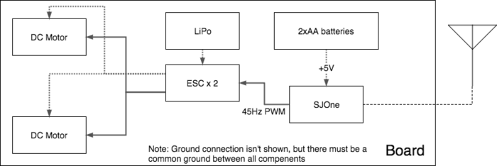
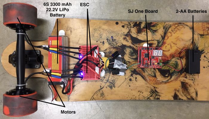
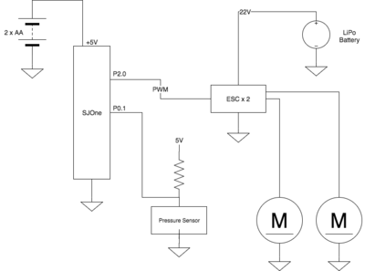
The main micro controller used for the skateboard portion was the SJ One Board. It is connected directly to the ESC's, which are then directly connected to the motors. The board also connects to pressure sensor as an additional feature to aide in controlling the skateboard. However, the ESC's and SJ One Board are powered separately. The SJ One board is powered via the 2 pack AA batteries, while the ESC's use the 6S 3300 mAh 22.2V Lithium Polymer (LiPo) Battery. The wire configuration can be seen in the figure below:
Remote Control
The main hardware components for the electric skateboard consist of:
- SJ One Board
- Slider Switch
- Button
- NiMH Battery
- Power Printed Circuit Board
- TFT LCD Screen
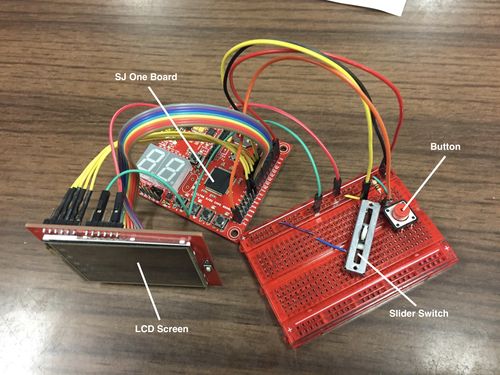
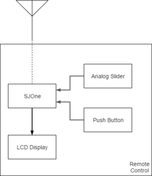
The remote control also uses an SJ One Board as the main micro controller. The slider switch, buttons and LCD Screens are all connected directly to the SJ One Board on the header pins on the right hand side, with respective resistors for the switch and button. Further details of which pins and functions are detailed in the Remote Control of the Hardware Interface below. The printed PCB will connect to the green portion noted as the "Battery Power" on the SJ One Board diagram on the main page. The remote control can be seen below:
Hardware Interface
The tables below show which pins and what functions are used for the external components such as switches and buttons. However, they can be changed as long as the functions are consistent with what is needed.
Motor Controller
| PIN number | Function | Component |
|---|---|---|
| P2.0 | PWM | ESC's |
| P0.1 | GPIO | Force Sensor |
For this project, Pin 2.0 was used to output a PWM signal to the ESC's. The ESC then sends an AC signal to drive the motors depending on the characteristics of the PWM signal. Pin 0.1 was used as a normal GPIO pin to receive input from the force sensor. We chose not to use one of the ADC pins on the board because we only care if there is a person on the board or not. We did not need to determine exactly how much force is applied to the force sensor.
Remote Control
| PIN number | Function | Component |
|---|---|---|
| P0.26 | ADC0.3 | Slider Switch |
| P0.0 | GPIO | Button |
| P2.0-2.7 | GPIO | TFT LCD Screen Display |
| P1.23, P1.28-P.31 | GPIO | TFT LCD Screen Controls |
The main components used for the remote control were a slider switch, a button, and a TFT LCD Screen for UI. The slider switch is an analog signal, which requires an ADC pin to be used for the input. The ADC pin is already configured during startup. Pin 0.26 was chosen as it is oneo of the pins that support ADC input. The button can be a GPIO, which will read when the switch is activated. Pin 0.0 was configured to be a GPIO pin to receive input for the switch. The TFT LCD Screen uses pins 0-7 on port 2 for the display, and pins 28-31 and pin 23 on port 1 for the control signals. Use of this LCD screen requires these pins to be configured as GPIO pins.
General Remote Interface
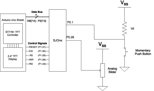
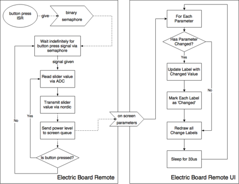
The slider switch is used to control the speed of the skateboard by varying resistance in the circuit. The button would be used to initiate that speed that is sent to the skateboard. The speed can only be changed once the button is being held. If the button is not held, the speed will default back to zero. This methodology was use was to limit communication between the boards, and thus, lower power consumption as well. For this instance, an ADC pin and a GPIO pin were needed for both the slider switch and the button, respectively. A diagram of the connections can be seen in the Figure below:
Once the button is pressed, it would activate an interrupt, which would immediately send the signal of the slider into a queue to communicate with the SJ One Board on the skateboard to control the motors. To send the information via wireless communication, the nordic wireless API ("wireless.h") was used. This is a wrap-around for "mesh.h".
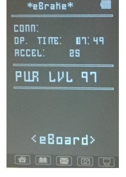
An LCD is driven by the SJone board to provide visual feedback on the board's wireless connection and speed information among others. It is controlled via an 8 bit data bus on pins P2.0 to P0.7 and 5 control pins on P1.31 to P1.28 and P1.23 for Reset, Chip Select, Write Mode, Read Mode, and Command/Data switching. The driver code it adapted from and AVR driver built for Arduino. The following figure shows the working LCD screen with the parameters given from the skateboard. The eBrake status is shown at the top, battery on the top right, connection status (Conn: ), operation time (Op. Time: ), acceleration, and power level.
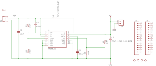
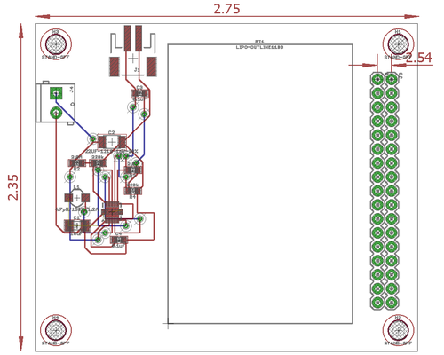
The designed PCB is a simple system to take the voltage provided from a small Lithium Ion battery (3.2-3.7 range) and upscale it to the necessary input voltage of the SJone board of 5 volts. The 5V and Gnd connections attach to the corresponding input connectors on the board to provide power to it and the accompanying LCD screen.
Software Design
Show your software design. For example, if you are designing an MP3 Player, show the tasks that you are using, and what they are doing at a high level. Do not show the details of the code. For example, do not show exact code, but you may show psuedocode and fragments of code. Keep in mind that you are showing DESIGN of your software, not the inner workings of it.
There are 5 main tasks that runs this project: RemoteUI, RemoteControl, ElectricBoardSender, ElectricBoardReceiver, and ElectricBoardControl.
The RemoteUI is used to display the information on the TFT LCD screen. It gets data from ElectricBoardSender. It obtains information in the form of OnScreenData struct. The OnScreenData struct is in OnScreenData.hpp, and is given by 5 parameters: bool connectionStatus, int eBrakeActive, int powerLevel, float batteryLevel, and int accelerometer. ConnectionStatus is the indicator to show if the remote control still has connection to the skateboards. It will frequently send messages and waits for the reply to see a connection still exists. The eBrakeActive is an indicator for the force sensor, the powerLevel for the speed of the skateboard, battery Level for the battery left in the remote, and accelerometer for the acceleration of the entire skateboard. The acceleration uses the instances of the SJ One board using AS.getX();
RemoteControl initializes the interrupts using eint3_enable_port0(), creates semaphores for buttonSignal, and creates screenQueue for OnScreenData struct. This function continuously checks to see if the button on the remote Control is pressed. If it is pressed, it will calculate powerLevel by getting the result of input divided by MAX_READ and multiplying it by 100. After calculating the powerLevel, it will send the data using sendPowerLevel() which uses the wireless API wireless_send() to electricBoardReceiver. If the button is not pressed, it will send a 0 for powerLevel.
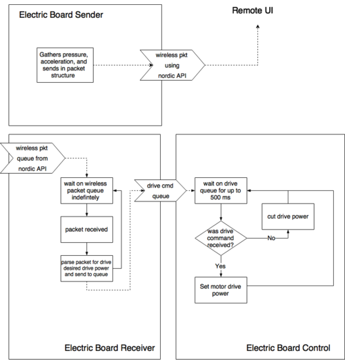
ElectricBoardSender specifically sends information such as acceleration and the pressure to the RemoteUI and ElectricBoardReceiver through wireless_send(). It sends the data as a uint32_t, where the 8 MSB are used for acceleration, while the last bit is used for pressure. The pressure is simply a "1" or a "0" to show if there is anything on the force sensor of the skateboard. This information would be seen on screen, and will give the ElectricBoardReceiver information about the force sensor.
ElectricBoardReceiver constantly checks for packets using wireless_get_rx_packet(). If it does receive a packet, it checks to see if driveQueue is created, along with the force sensor connection. If either driveQueue is not created or there is nothing on the force sensor, it will not send. If successful, it will then parse the packet, and send the data to driveQueue.
ElectricBoardControl is where the controls of the motors and ESCs coming in. It uses "lpc_pwm.hpp", and the frequency for the ESC is defined by PWM_FREQ_HZ = 45. CommandQueue is created, and motorChannel1 and motorChannel2 are defined. This function checks to see if commandQueue is either empty or not empty. If it is empty, driveLevel is set at 0. If it is not empty, it will continuously send driveLevel using driveMotor(). The driveMotor() function calculates the duty cycle from the given power level. It sets ceilings and floors for powerLevel to ensure that it does not go above 100, or below 0, and duty cycle is calculated by the sum of IDLE_DUTY and difference of MAX_DUTY and IDLE_DUTY and multiple by powerLevel/100. it is then set using motorChannelX->set(dutyCycle).
Implementation
This section includes implementation, but again, not the details, just the high level. For example, you can list the steps it takes to communicate over a sensor, or the steps needed to write a page of memory onto SPI Flash. You can include sub-sections for each of your component implementation.
There are 3 main sections for implementing this project: connecting components, calibration for ESCs and establishing wireless communication.
- Connect sensors and switches connect to the SJ One Boards
- Ensure that the Slider Switch (ADC) and Button (GPIO) are configured correctly to SJ One Board for Remote Control
- The button can connected via a pull-up or pull-down resistor configuration, but the input logic must be changed accordingly.
- Ensure that the Force Sensor (GPIO) are configured correctly to the SJ One Board for Skateboard
- The force sensor is like a variable resistor that acts as an open circuit without any pressure on it. Using a pull-up resistor we can read the pressure sensor as if it were a button (pressed = logic low, depressed = logic high).
- Ensure that the connections for TFT LCD Screen (GPIO) is correct for Remote control
- Ensure that the Slider Switch (ADC) and Button (GPIO) are configured correctly to SJ One Board for Remote Control
- Verify input signals to the ESC's using an oscilloscope to properly calibrate the ESC's on startup
- Should be able to get frequency to turn on/off motors via ESCs
- Should be able to get duty cycle to change the speed of the motors
- Important to establish the duty cycles that correlate to the ESC's max/idle/reverse drive powers.
- Establish wireless communication (mesh API)
- Know how to send data
- Know how to parse the packet
Testing & Technical Challenges
Describe the challenges of your project. What advise would you give yourself or someone else if your project can be started from scratch again? Make a smooth transition to testing section and described what it took to test your project.
Include sub-sections that list out a problem and solution, such as:
Hardware Mounting
Most electric skateboards have a housing which encases the LiPo battery, ESCs, and receiver that are necessary to be mounted onto the board. However, all commercially available housings for skateboards were too small for the components ordered. This is mainly due to the size of the LiPo battery. The LiPo battery being used for this project is not one typically used for electric skateboards. It is very thick compared to the ones that are used for electric skateboards. Velcro mounting tape will be used instead of the housing enclosure for this project because it has a strong enough hold and can easily be removed without damaging the equipment. This is only being used as a temporary solution until a thinner LiPo battery can replace the existing one and an appropriate housing enclosure can be ordered.
Electronic Speed Controllers
The electronic speed controllers (ESC) were ordered as part of a kit. However, no specification sheet or documentation came with the ESC's. ESC's usually receive and interpret an input PWM signal to drive motors at a specified speed. The duty cycle of the PWM signal required by the ESC's to drive the motor was unknown. We requested a data sheet for the ESC's from the company that we ordered from but there was no response.
An existing wireless receiver and remote came with the kit as well, but, for this project, we wanted to design and implement our own remote control. The output of the wireless receiver was observed with an oscilloscope after connecting these two components to the board. From the oscilloscope readings, proper PWM signals were determined for an idle state, maximum velocity state, and maximum reverse velocity state for the ESC's.
Wireless Communication Range
The electric skateboard and wireless communication were initially working. However, with further testing, it was found that the wireless communication was unstable for the nordic wireless chip on the SJ One board for distances over approximately 3 feet. The data transfer rate was lowered to 250 kB/s from 2000 kB/s which increased the wireless communication distance to about 4 feet. However, we wanted a much more stable connection so antennas were added. In incorporating antennae, please note that the NP-RMA port on the SJ One Board is female. Most Antennae will come female as well, so we bought a male-male adapter to put in.
Conclusion
The most important aspect of this project was the application of knowledge. This, in turn, enables us to know how to use the tools, rather than what the tools do. We were able to apply and extend the knowledge of embedded systems and FreerRTOS to create a project that our group was interested in. This showed the use of all aspects of CMPE 244, from the creation of tasks, using semaphores, communicating between tasks with queues, writing drivers, and managing multiple inputs at once.
Project Video
Project Source Code
References
Acknowledgement
We want to thank Professor Preetpal Kang for the CMPE 244 class and the concepts taught in the class. These concepts have helped us during the implementation of the project.
References Used
Appendix
You can list the references you used.
