Difference between revisions of "S17: Sphero Droid"
Proj user11 (talk | contribs) (→Project Title) |
Proj user11 (talk | contribs) (→Project Source Code) |
||
| (227 intermediate revisions by 2 users not shown) | |||
| Line 1: | Line 1: | ||
| − | |||
| − | |||
| − | |||
| − | |||
| − | |||
| − | |||
| − | |||
| − | |||
| − | |||
| − | |||
| − | |||
| − | |||
| − | |||
| − | [[File: | + | |
| + | [[File:CmpE244_S17_SpheroDroid_Botview.gif|600px|thumb|center|Sphero Droid]] | ||
=== Abstract === | === Abstract === | ||
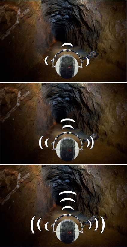
Robots are revolutionizing almost every industry, primarily in the sectors where human safety is at risk. In hazardous working conditions such as in the mining industry, the lack of knowledge about the geographic nature and the environmental conditions of the mine hinder the rescue operations. Autonomous robots are being employed to improve the plight of mine workers and rescue operators. The robotic vehicle can explore the inaccessible and unworkable mines and disaster-affected areas and send valuable information to the teams to assist in search and rescue operations. But traditional robots could be rendered useless if they are overturned or in terrains having staircases and ledges. Also, there is a possibility of failure of the electrical and mechanical components exposed to the harsh environmental conditions. An autonomous spherical robot is a better option since its shape offers better robustness and rigidity. The spherical robot will enclose all the components within it and will not have any wheels or legs on its exterior. This feature enables it to operate in any hazardous conditions since there will be very less chance for the components to get damaged by the surrounding environment. The spherical design allows it to easily maneuver in different types of terrain, be it stairs or corners, and have no risk of being overturned. These advantages enable the robot for many applications such as exploration and mapping of access routes, surveillance and rescue operations in uncomfortable working conditions. | Robots are revolutionizing almost every industry, primarily in the sectors where human safety is at risk. In hazardous working conditions such as in the mining industry, the lack of knowledge about the geographic nature and the environmental conditions of the mine hinder the rescue operations. Autonomous robots are being employed to improve the plight of mine workers and rescue operators. The robotic vehicle can explore the inaccessible and unworkable mines and disaster-affected areas and send valuable information to the teams to assist in search and rescue operations. But traditional robots could be rendered useless if they are overturned or in terrains having staircases and ledges. Also, there is a possibility of failure of the electrical and mechanical components exposed to the harsh environmental conditions. An autonomous spherical robot is a better option since its shape offers better robustness and rigidity. The spherical robot will enclose all the components within it and will not have any wheels or legs on its exterior. This feature enables it to operate in any hazardous conditions since there will be very less chance for the components to get damaged by the surrounding environment. The spherical design allows it to easily maneuver in different types of terrain, be it stairs or corners, and have no risk of being overturned. These advantages enable the robot for many applications such as exploration and mapping of access routes, surveillance and rescue operations in uncomfortable working conditions. | ||
| − | == Objectives & Introduction == | + | == '''Objectives & Introduction''' == |
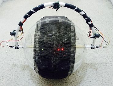
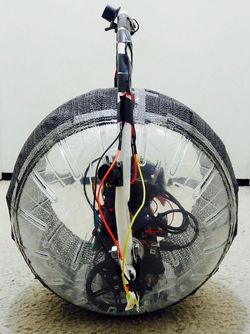
| − | The objective of this project is to design an autonomous spherical robot with sensors, Global Positioning System (GPS) module, Bluetooth module and other control units interfaced to the microcontroller, which navigates its way | + | The objective of this project is to design an autonomous spherical robot with sensors, Global Positioning System (GPS) module, Bluetooth module and other control units interfaced to the microcontroller, which navigates its way exploring the path and avoiding obstacles. The temperature and the route followed by the robot can be logged on the SD card. These features enable the robot for many applications such as exploration and mapping of access routes, surveillance, and rescue operations in uncomfortable working conditions. |
| + | |||
| + | {| | ||
| + | |[[File:CmpE244_S17_SpheroDroid_Botzoomview.jpg|370px|thumb|left|Sphero Droid front view]] | ||
| + | | | ||
| + | | | ||
| + | | | ||
| + | |[[File:CmpE244_S17_SpheroDroid_Botsideview.jpg|250px|thumb|center|Sphero Droid side view]] | ||
| + | | | ||
| + | | | ||
| + | | | ||
| + | |[[File:CmpE244_S17_SpheroDroid_internal_view.jpg|450px|thumb|right|Sphero Droid Internal view]] | ||
| + | |} | ||
=== Team Members & Responsibilities === | === Team Members & Responsibilities === | ||
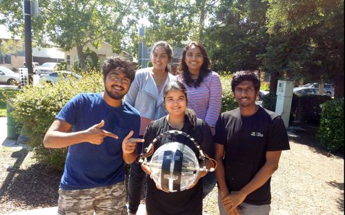
| − | * <font color="clouds"> Harshitha Bura | + | [[File:CmpE244_S17_SpheroDroid_Teampic.jpg|right|500px|thumb|GPS interface with SJOne board via UART]] |
| − | ** | + | * <font color="clouds"> [https://www.linkedin.com/in/harshitha-bura-4926727a/ Harshitha Bura] |
| − | ** | + | ** GPS and Temperature Sensor<br> |
| − | * | + | ** SDCard<br> |
| − | ** | + | ** Wiki page reporting<br> |
| − | ** | + | ** Code integration[Gps and Sdcard card tasks]<br> |
| − | ** | + | * <font color="red"> [https://www.linkedin.com/in/naveenbr/ Naveen Kumar Bhuthakatanahalli Ramalingaiah] |
| − | * | + | ** SDCard<br> |
| − | ** | + | ** Bluetooth module and Android Aplication<br> |
| − | ** | + | ** Hardware design and implementation <br> |
| − | * | + | ** Code integration[Andriod task integration with overall tasks integration]<br> |
| − | ** | + | * <font color="green"> [https://www.linkedin.com/in/shivam-chauhan-a1ab2ba3/ Shivam Chauhan] |
| − | ** | + | ** PCB Designing<br> |
| − | * <font color=" | + | ** Servo Motor<br> |
| − | ** | + | ** Ultrasonic Range Finders<br> |
| − | ** | + | ** Hardware design and implementation <br> |
| − | < | + | ** Code integration[Overall tasks integration]<br> |
| − | + | * <font color="carrot"> [https://www.linkedin.com/in/sushma-nagaraj/ Sushma Nagaraj] | |
| − | + | ** Servo Motor<br> | |
| + | ** Ultrasonic Range Finders<br> | ||
| + | ** Wiki page reporting<br> | ||
| + | ** Code integration[Servo,DC motor and Sensor tasks]<br> | ||
| + | *<font color="black"> [https://www.linkedin.com/in/virginia-allita-menezes Virginia Menezes] | ||
| + | ** DC Motors <br> | ||
| + | ** Wiki page reporting<br> | ||
| + | ** Code integration[Servo and DC motor tasks]<br> | ||
| + | == '''Schedule''' == | ||
{| class="wikitable" | {| class="wikitable" | ||
| Line 106: | Line 114: | ||
| | | | ||
* Testing and Debugging | * Testing and Debugging | ||
| − | * Work on extra features | + | * Work on extra features |
* Work on Project Report on Wiki | * Work on Project Report on Wiki | ||
| − | | | + | | Done |
| − | | | + | | 5/16 |
|- | |- | ||
! scope="row"| 7 | ! scope="row"| 7 | ||
| Line 117: | Line 125: | ||
* Testing and Debugging | * Testing and Debugging | ||
* Project Presentation and update Wiki | * Project Presentation and update Wiki | ||
| − | | | + | | Done |
| − | | | + | | 5/24 |
|- | |- | ||
! scope="row"| 8 | ! scope="row"| 8 | ||
| Line 125: | Line 133: | ||
| | | | ||
* Complete Wiki Report and Final Demo | * Complete Wiki Report and Final Demo | ||
| − | | | + | | Done |
| − | | | + | | 5/25 |
|} | |} | ||
| − | == Parts List & Cost == | + | == '''Parts List & Cost''' == |
{| class="wikitable" | {| class="wikitable" | ||
| Line 225: | Line 233: | ||
|} | |} | ||
| − | == Design | + | == '''Design and Implementation''' == |
| − | The | + | === '''System Block diagram''' === |
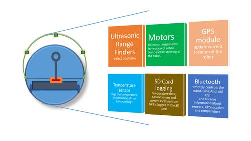
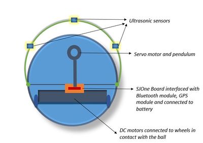
| + | The Sphero Droid contains ultrasonic, motors, GPS, Bluetooth as the main modules of communication. This is illustrated in the image below. The robot is controlled and navigated via a load which pulls it down and wheels which touch the ball from within. This will facilitate the ball movement. | ||
| + | {| | ||
| + | |[[File:CmpE244_S17_SpheroDroid_Bot_modules.JPG|left|500px|thumb|Robot interface]] | ||
| + | | | ||
| + | | | ||
| + | | | ||
| + | | | ||
| + | | | ||
| + | | | ||
| + | | | ||
| + | | | ||
| + | | | ||
| + | | | ||
| + | | | ||
| + | |[[File:CmpE244_S17_SpheroDroid_Bot_parts.JPG|right|400px|thumb|Within the Robot]] | ||
| + | |} | ||
| + | |||
| + | === System State Diagram === | ||
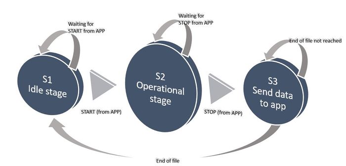
| + | The operation of SpheroDroid is divided into states as shown below. This mainly constitutes the start, operational and stop stages. The start is provided by Android application and the device moves forward. Different tasks will start when start condition is provided. The device will stop and when signalled from android application. The MCU will later send the GPS coordinate values which was written and restart when EOF is reached, moving to state one again. | ||
| + | [[File:CmpE244_S17_SpheroDroid_Bot_state_diagram.JPG|center|700px|thumb|State Diagram]] | ||
=== Hardware Design === | === Hardware Design === | ||
| − | + | We have four distinct hardware modules used in this project: | |
| + | * Ultrasonic Range Finders (sensors) | ||
| + | * Motors | ||
| + | * GPS Module | ||
| + | * Bluetooth Module | ||
| + | |||
| + | ==== Ultrasonic Range Finders ==== | ||
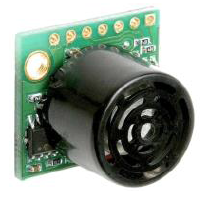
| + | Used MB1010 LV-MaxSonar-EZ21 Ultrasonic Rangefinder sonar sensors, which can from 6-inches to 254-inches, with 1-inch resolution. Any object from 0-inches to 6-inches is typically | ||
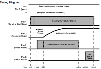
| + | ranged as 6-inches. They are used in PW mode for outputting. For efficient working of sensors without any crosstalk, we have configured 3 sensors in the chaining mode called AN output commanded loop. This mode of configuration uses 5 pins of each sensor such as VCC = +5V, GND, TX, RX, and PWM. While triggering, the first sensor RX pin is held high for a time period > 20μs and < than 48ms.This will start the sensor chain. The first sensor will range, then trigger the second sensor to the range and so on for all the sensor in the array. | ||
| + | |||
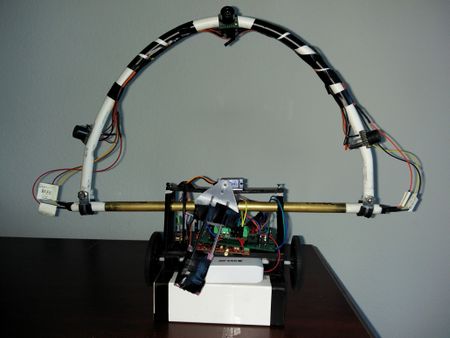
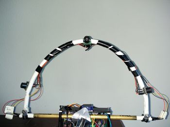
| + | Mounting of the sensors is made on a curved platform such that the sensors are aimed with a positive slope and not horizontally. This decision is made in order to avoid interference with the ground due to the wide range of detection by the sensors. | ||
| + | {| | ||
| + | |[[File:CmpE244_S17_SpheroDroid_MaxSonarsensor.png|left|600px|thumb|MB1010 LV-MaxSonar-EZ21 Ultrasonic sensor]] | ||
| + | | | ||
| + | | | ||
| + | | | ||
| + | | | ||
| + | | | ||
| + | | | ||
| + | | | ||
| + | | | ||
| + | | | ||
| + | | | ||
| + | | | ||
| + | | | ||
| + | |[[File:CmpE244_S17_Sensors_timing_diagram.PNG|centre|400px|thumb|Sensor timing diagram]] | ||
| + | | | ||
| + | | | ||
| + | | | ||
| + | | | ||
| + | | | ||
| + | | | ||
| + | | | ||
| + | | | ||
| + | | | ||
| + | | | ||
| + | | | ||
| + | | | ||
| + | |[[File:CmpE244_S17_SpheroDroid_SensorMounting.jpg|right|350px|thumb|Sensor's mounting platform]] | ||
| + | |} | ||
| + | |||
| + | ==== Motors ==== | ||
| + | |||
| + | * '''DC Motors''' | ||
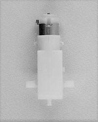
| + | The DC motors used in the project are 100 RPM low-cost single shaft straight geared motors. They are suitable for lightweight robots that do not require high power or torque.<br> The DC motors are connected to the wheels which are in contact with the base of the ball. The DC motors are driven by a driver module which controls the motor direction and speed. | ||
| + | {| | ||
| + | |[[File:CmpE244_S17_SpheroDroid_motors.jpg|left|200px|thumb|Plastic geared motor]] | ||
| + | |[[File:CmpE244_S17_SpheroDroid_Motor_Driver.JPG|center|400px|thumb|Driver module]] | ||
| + | |[[File:CmpE244_S17_SpheroDroid_Motors-Motor_Driver.JPG|right|500px|thumb|Control inputs of driver module]] | ||
| + | |} | ||
| + | |||
| + | * '''Servo Motors''' | ||
| + | LS-0009AF Servo motor used is controlled by sending an electrical pulse of variable width or pulse width modulation (PWM), through the control wire. Maximum deflection which can be achieved by using this servo is 90°.The motor's neutral position is defined as the position where the servo has the same amount of potential rotation in the both the clockwise or counter-clockwise direction. The PWM sent to the motor determines the position of the shaft, and based on the duration of the pulse sent via the control wire; the rotor will turn to the desired position. The servo motor expects to see a pulse every 2000 microseconds and the length of the pulse will determine how far the motor turns. For example, a 1500microseconds pulse will make the motor turn to the 45° position. Shorter than 1500microseconds moves it in the counter-clockwise direction toward the 0° position, and any longer than 1500microseconds will turn the servo in a clockwise direction toward the 90° position. | ||
| + | |||
| + | {| | ||
| + | | | ||
| + | | | ||
| + | | | ||
| + | | | ||
| + | | | ||
| + | | | ||
| + | | | ||
| + | | | ||
| + | | | ||
| + | | | ||
| + | | | ||
| + | | | ||
| + | | | ||
| + | | | ||
| + | | | ||
| + | | | ||
| + | | | ||
| + | | | ||
| + | ||||||||||||||||||||||||||||||||||||||||||||||||||||||||||[[File:CmpE244_S17_SpheroDroid_ServoMotorBasic.JPG|left|300px|thumb|Servo motor LS-0009AF]] | ||
| + | | | ||
| + | | | ||
| + | | | ||
| + | | | ||
| + | | | ||
| + | | | ||
| + | | | ||
| + | | | ||
| + | | | ||
| + | | | ||
| + | |[[File:CmpE244_S17_SpheroDroid_ServoMotor_working.gif|right|400px|thumb|Servo motor dutycycle]] | ||
| + | |} | ||
| + | |||
| + | The hardware implementation of how the DC motors are connected to the wheels which are driven from the SJOne board and how the servo motor is connected with the pendulum to steer the robot in right or left direction can be viewed in the figure below. | ||
| + | |||
| + | [[File:CmpE244_S17_SpheroDroid_Bot_motors_hardware_design.JPG|center|500px|thumb|Internal Hardware connection (Motors)]] | ||
| + | |||
| + | ==== GPS module ==== | ||
| + | |||
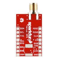
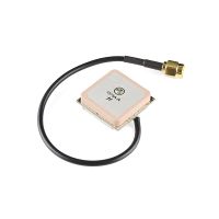
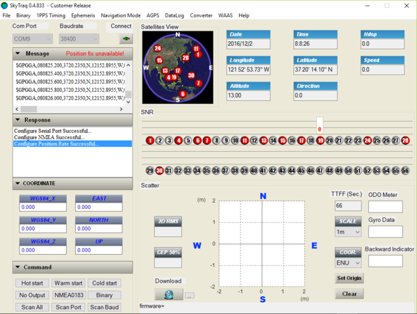
| + | In the project, we use GPS module ''Sparkfun Venus638FLPx'' to log the current location of the robot. An antenna is connected to the SMA connector of the GPS module. The software Skytraq GPS viewer is used to configure it. The module is configured to send information in NMEA message format (using the GPGGA (Global Positioning System Fix Data). We configured it to run at a baud rate of 38400bps and update rate of 2 Hz. | ||
| + | |||
| + | {| | ||
| + | |[[File:CmpE244_S17_SpheroDroid_BT.jpg|right|200px|thumb|GPS Module]] | ||
| + | |[[File:CmpE244_S17_SpheroDroid_GPS_Logger_Antenna.jpg|right|200px|thumb|Antenna for the GPS module]] | ||
| + | |[[File:CmpE244_S17_SpheroDroid_GPS_Viewer.PNG|right|600px|thumb|GPS Configuration Software]] | ||
| + | |} | ||
| + | |||
| + | There are three modes of operation: | ||
| + | |||
| + | 1. '''Hot Start''': This enables the GPS to obtain a fix in a very less time if it is connected to a 3.3v coin cell battery and it is switched on again within two hours after switching it off. Connecting the battery will help it to store information about the previous fix. | ||
| + | |||
| + | 2. '''Warm Start''': In this mode, it will take the GPS more time to obtain a fix compared to the hot start as the module has been switched off for more than hours. But as the battery is connected and the information of the previous fix is available it will take less time compared to the cold start. | ||
| + | |||
| + | 3. '''Cold Start''': As the battery is not connected and information about the previous fix is not available in this mode, it will take a lot of time to obtain a fix. | ||
| + | |||
| + | In our project, we have connected a 3V external battery (VBAT) to the module so that it does not take a long time to get a satellite fix even after turning off and on. | ||
| + | |||
| + | The NMEA message looks as follows: | ||
| + | |||
| + | GGA - Global Positioning System Fix Data : '''$GPGGA,hhmmss.sss,ddmm.mmmm,a1,dddmm.mmmm,a2,V,xx,x.x,x.x,M,,,,xxxx*hh<CR><LF>''' | ||
| + | |||
| + | where, | ||
| + | Time - hhmmss.sss | ||
| + | Latitude - ddmm.mmmm | ||
| + | Direction - (a1) - N or S | ||
| + | Longitude - dddmm.mmmm | ||
| + | Direction - (a2) - E or W | ||
| + | Validity - V - 0 or 1. 0 means invalid and 1 means valid. | ||
| + | |||
| + | After this data is received by the SJOne board, string manipulation is done to extract the latitude and longitude from the string (if the data is valid) and they are converted to decimal minutes so that they can be sent to an android application where they are plotted on a map. | ||
| + | |||
| + | ==== Bluetooth module ==== | ||
| + | |||
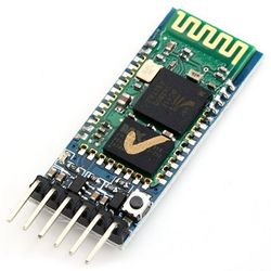
| + | Bluetooth module HC-05 is used to communicate between the spherical robot and mobile application. It is implemented to establish the connection between the two so that we can remotely control the robot (to send start and stop signals) and receive the data from the robot directly on the Android application. The data being sent by the robot is current GPS location, ultrasonic range sensor values, and temperature sensor values. | ||
| + | |||
| + | {| | ||
| + | |||||||||||||||||||||||||||||||||||||||||||||||||||||||||||||||||||||||||||| | ||
| + | [[File:CmpE244_S17_SpheroDroid_HC05_module.jpg |thumb|left|250px|Bluetooth module HC-05]] | ||
| + | |[[File:CmpE244_S17_SpheroDroid_Bluetooth_HC05.JPG |thumb|center|250px|HC-05 Pin connections]] | ||
| + | |} | ||
=== Hardware Interface === | === Hardware Interface === | ||
| + | We have four major hardware modules interfaced with a single SJOne board using different communication protocols. | ||
| + | For simplicity sake, we have given a description of how each module is individually interfaced with the SJOne board. | ||
| + | In reality, all these modules are connected to a single SJOne microcontroller. | ||
| + | |||
| + | ==== Ultrasonic Range Finders ==== | ||
| + | The ultrasonic range finders have been interfaced with the SJOne board using PWM. To avoid the crosstalk between the sensors and to improve the efficiency, sensors are configured to work in chaining mode. In our project, the Right sensor is triggered first by holding the RX pin high for >20μs and < 48ms.This will start the sensor chain. The Right sensor will range, then trigger the Front sensor to the range which in turn trigger the last Left sensor. | ||
| + | |||
| + | {| | ||
| + | ||||||||||||||||||||||||||[[File:CmpE244_S17_SpheroDroid_Sensor_interface.png|left|400px|thumb|Ultrasonic range finders interfacing with SJOne board via PWM]] | ||
| + | | | ||
| + | | | ||
| + | | | ||
| + | | | ||
| + | | | ||
| + | | | ||
| + | | | ||
| + | | | ||
| + | | | ||
| + | | | ||
| + | | | ||
| + | |[[File:CmpE244_S17_SpheroDroid_Sensorschainedtriggering.png|600px|thumb|right|Sensor's chained triggering]] | ||
| + | |} | ||
| + | ==== Motors ==== | ||
| − | + | The DC motor is connected with the SJOne board via the motor driver module using GPIO. | |
| + | The GPIO signals from SJOne board provide inputs to the motor driver module, which in turn drives the DC motors in forward or reverse direction or stop signal. | ||
| + | Servo motor is interfaced with the SJOne board using PWM. | ||
| + | {| | ||
| + | |||||||||||||||||||||||||||||||||||||||||||||||||||[[File:CmpE244_S17_SpheroDroid_DCMotor_interface.JPG|left|400px|thumb|DC Motors and driver module connected to SJOne board using GPIO]] | ||
| + | | | ||
| + | | | ||
| + | | | ||
| + | | | ||
| + | | | ||
| + | | | ||
| + | | | ||
| + | |[[File:CmpE244_S17_SpheroDroid_Servomotorinterfacing.PNG|right|500px|thumb|Servo motors interface with SJOne board via PWM]] | ||
| + | |} | ||
| − | [[File: | + | ==== GPS Module ==== |
| + | GPS module communicates with SJOne board via UART. The antenna is connected to the SM connector of the GPS module. A 3.3v supply is given to the module and its Rx and Tx pins are connected to the Tx and Rx pins of the SJOne board respectively. UART 2 of the SJOne board is used for the GPS module and it is configured to run at a baud rate of 38400bps. | ||
| + | {| | ||
| + | | | ||
| + | ||||||||||||||||||||||||||||||||||||||||||||||||||||||||||||||||||||||||||||||||||||||||||||||||||||||||||||||||||||||||||||||||||||||||||||||||||||||||||||[[File:CmpE244_S17_SpheroDroid_GPS_Connections.png|center|500px|thumb|GPS interface with SJOne board via UART]] | ||
| + | | | ||
| + | |} | ||
| − | + | ==== Bluetooth module ==== | |
| − | + | ||
| − | + | The Bluetooth HC-05 module is connected with the SJOne board via UART communication.The bluetooth module communicates using the Tx and Rx pins of HC-05. This device independently connects to any external bluetooth master device. The HC-05 can work as a Master or a Slave. For our application the device sends the GPS data from SD card and also receive data from Android Application. Since the device can be connected independently without the MCU it can be connected and used with MCU restarting and not affecting the connectivity. UART3 is used for serial communication. The Baud rate set is 9600 for communication between bluetooth device and Android Application. | |
| − | + | ||
| − | + | ||
| − | + | {| | |
| − | + | |||||||||||||||||||||||||||||||||||||||||||||||||||||||||||||||||||||||||||||||||||||||||||||||||||||||||||||||||||||||||||||| | |
| − | + | [[File:CmpE244_S17_SpheroDroid_BT_interface.jpg|center|500px|thumb|Bluetooth connection with SJOne via UART]] | |
| − | + | |} | |
| − | |||
| − | |||
| − | |||
| − | |||
| − | |||
| − | |||
| − | |||
| − | |||
| − | |||
=== Software Design === | === Software Design === | ||
| − | |||
| − | === | + | ==== Ultrasonic Range Finder and Motors ==== |
| − | + | The motors working depends on the input values of sensors (ultrasonic range finders). Depending on whether the sensors can detect an obstacle in its path, the motors continue to run in the forward direction or the servo motor steers the robot towards right or left. The diagrams below shows the algorithm of the logic behind it. | |
| + | {| | ||
| + | ||||||||||||||||||||||||||||||||||||||||[[File:CmpE244_S17_SpheroDroid_Sensors_logic.jpg|left|400px|thumb|Sensors logic]] | ||
| + | |||||||||||||||||||||||[[File:CmpE244_S17_SpheroDroid_motor_logic.jpg|right|550px|thumb|DC and servo motor logic]] | ||
| + | |} | ||
| + | |||
| + | ==== GPS module ==== | ||
| + | |||
| + | The GPS-SJOne board communication is done via UART. Whenever data is received by the SJOne board from the GPS module, a UART interrupt occurs and the data is stored in a buffer. The data is checked if it is valid or not. If it is valid, the latitude and longitude are written to the SDCard. Otherwise, it is written that no GPS signal was available at that point. The flowchart is shown below. | ||
| + | |||
| + | |||
| + | [[File:CmpE244_S17_SpheroDroid_GPS_Flowchart.jpg|center|700px|thumb|Software Flow for the GPS]] | ||
| + | |||
| + | === PCB Design === | ||
| + | |||
| + | We have used EAGLE software to design the PCB layout. The PCB layout is the most crucial part of the project, it may make or break the performance and working of the circuit. The first step towards designing the PCB is including all the required components into the schematic workspace and making connections between them. Once the schematic is ready, next step is to create the board layout from the schematic, which is easy, since EAGLE links the layout file and schematic together automatically. | ||
| + | |||
| + | |||
| + | [[File:CmpE244_S17_SpheroDroid_PCBschematic.PNG|center|800px|thumb|PCB Schematic]] | ||
| + | |||
| + | |||
| + | [[File:CmpE244_S17_SpheroDroid_PCBboard.PNG|center|600px|thumb|PCB layout]] | ||
| + | |||
| + | |||
| + | |||
| + | {| | ||
| + | ||||||||||||||||||||||||||||||||||||||||||||||||||||||||||||||||||||||||||||||||||||||||||||||||||||||||[[File:CmpE244_S17_SpheroDroid_PCB.jpg|center|400px|thumb|PCB board with components]] | ||
| + | |[[File:CmpE244_S17_SpheroDroid_PCBwithSJone.jpg|right|400px|thumb|PCB board connected to SJOne board]] | ||
| + | |} | ||
| + | |||
| + | === SD Card Writing === | ||
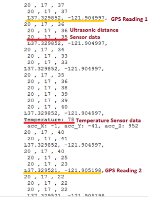
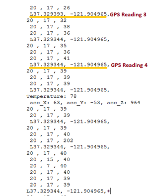
| + | The data from the GPS, temperature sensor, accelerometer and ultrasonic range finders is continuously being logged onto an SDCard. The purpose of this is to send the data to a remote location once the robot's exploration is complete. In our case, we are reading the data from the SDCard and sending it to a mobile application. The mobile application will receive the latitude and longitude values and will plot a path on a map connecting the geographical locations the robot has visited. Screenshots of the data being logged are shown in the following figures. It can be observed that different GPS locations are being logged onto the SDCard as the robot travels. | ||
| + | |||
| + | {| | ||
| + | |||||||||||||||||||||||||||||||||||||||||||||||||||||||||||||||||||||||||||||||||||||||||||||||||||||||||||||||[[File:CmpE244_S17_SpheroDroid_Data_written_in_text_file_GPS_Data1&2.png|300px|thumb|left|GPS Location 1 and 2 written to SDCard]] | ||
| + | | | ||
| + | | | ||
| + | | | ||
| + | ||||||||||||||||||||||||||[[File:CmpE244_S17_SpheroDroid_Data_written_in_text_file_GPS_Data3&4.png|300px|thumb|right|GPS Location 3 and 4 written to SDCard]] | ||
| + | | | ||
| + | | | ||
| + | | | ||
| + | |} | ||
| + | |||
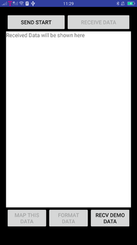
| + | === Android Application === | ||
| + | The Android Application development was divided into multiple stages: | ||
| + | |||
| + | |||
| + | 1. Building the first App with interactive buttons | ||
| + | |||
| + | 2. Communicating with Bluetooth module, hence tried and used many approaches. | ||
| + | |||
| + | 3. Sending and Receiving data between Activities within Android App | ||
| + | |||
| + | 4. Transmission and Reception of data from bluetooth device connected to SJ One board. | ||
| + | |||
| + | 5. Plotting the data on Google Maps using google maps API. | ||
| + | |||
| + | |||
| − | + | {| | |
| − | + | |[[File:CmpE244_S17_SpheroDroid_AndroidAppIcon.jpg|left|200px|thumb|Android App Icon]] | |
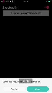
| − | + | |[[File:CmpE244_S17_SpheroDroid_AndroidBluetoothTurnOn.png|left|200px|thumb|Permission to turn ON Bluetooth]] | |
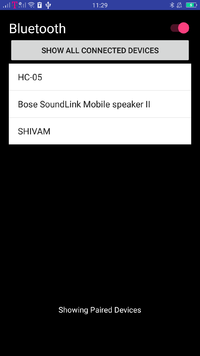
| + | |[[File:CmpE244_S17_SpheroDroid_AndroidBluetoothPairedDevices.png|left|200px|thumb|Android App connected to Bluetooth]] | ||
| + | |} | ||
| + | {| | ||
| + | |[[File:CmpE244_S17_SpheroDroid_AndroidStartButton.png|right|200px|thumb|Kick start off from the Android App]] | ||
| + | |[[File:CmpE244_S17_SpheroDroid_AndroidStartReceivedData.png|right|200px|thumb| GPS location values received from Sphero droid]] | ||
| + | |[[File:CmpE244_S17_SpheroDroid_AndroidStartGPSlocationsonMap.png|200px|thumb|right|GPS location on Google Map]] | ||
| + | |} | ||
| − | + | == '''Testing & Technical Challenges''' == | |
| − | + | 1. '''Incorrect sensor values at different voltage levels''' - This was solved by providing stable IC output at 3.3V. | |
| − | |||
| − | == Conclusion == | + | 2. '''Unbalanced weight distribution and unstable platform''' - Because of unbalanced weight distribution, the sensors platform connected to the axle was unstable while running. |
| − | + | This solved by changing the hardware positioning internally. | |
| + | |||
| + | 3. '''Abnormal restart of the microcontroller when motors begin''' - This was solved by providing sufficient power supply and running all modules on single voltage of 3.3V | ||
| + | |||
| + | 4. '''Problem in steering the robot''' - This issue was solved by increasing the weight connected to the servo motor and the length of the pendulum. | ||
| + | |||
| + | 5. '''Difficulty in finding the end of file while reading from the SD Card''' - A special character was used to while writing into the file to indicate the end of the file. | ||
| + | |||
| + | 6. '''Unable to read corrupted SD card''' - On starting the robot, we first validate if the SD card is ready to communicate using sd_initialize(), and if not, then the robot will not respond to start from the application. | ||
| + | |||
| + | 7. '''Initially, we had to dismantle the robot every time and remove the internal modules to restart the robot''' - We avoided this by using a volatile variable that is sent from the android application. The low priority task that runs will check if the variable has changed, and if changed then it will restart. | ||
| + | |||
| + | == '''Conclusion''' == | ||
| + | |||
| + | We have successfully designed and implemented an autonomous spherical robot. This project has helped us understand the implementation of FreeRTOS concepts like prioritizing tasks and using semaphore and mutex for SD card reading and writing. We learned to implement our own communication protocol drivers such as UART and I2C. Even though the hardware implementation was tedious and challenges like unbalanced weight distribution and unstable platform took some time to resolve, it was all an overwhelming learning experience. | ||
=== Project Video === | === Project Video === | ||
| − | + | ||
| + | 1. Final project video - https://youtu.be/8crZVj166tY | ||
| + | |||
| + | 2. Sensor and motor testing - https://youtu.be/_Tye2R-DpHY | ||
| + | |||
| + | 3. First Indoor run (checking mechanical structure) - https://youtu.be/JykHXq53Ipg | ||
| + | |||
| + | 4. Steering of the robot using pendulum with the servo motor - https://youtu.be/N-BSanpUjbk | ||
=== Project Source Code === | === Project Source Code === | ||
| − | |||
| − | == References == | + | * [https://github.com/SushmaNagaraj/Sphericalrobot/tree/Final_Master_branch/Final_Master_branch SpheroDroid Github Link] |
| − | === Acknowledgement === | + | |
| − | + | == '''References''' == | |
| + | === '''Acknowledgement''' === | ||
| − | + | We would like to thank Prof. Preetpal Kang for encouraging us and guiding us throughout the semester. We are grateful to you for making this class such a valuable learning experience for us. We would also like to thank the ISA members who have been there to help us and for being approachable anytime. | |
| − | |||
| − | === | + | === '''References Used''' === |
| − | + | [1] CMPE 244 Lecture notes from Preetpal Kang, Computer Engineering, San Jose State University. Jan-May 2017. | |
| + | [2] [http://stackoverflow.com Android & Java Forums(www.stackoverflow.com)] | ||
| + | [3] [https://developer.android.com/training/index.html Android References (Developer Android)] | ||
| + | [4] [http://www.maxbotix.com/documents/LV-MaxSonar-EZ_Datasheet.pdf MaxSonar datasheet] | ||
| + | [5] [http://www.gearbest.com/other-accessories/pp_227678.html?currency=USD&lkid=10133927&gclid=CLaiv83FmtACFRB0fgode7oD0g Bluetooth Module HC-05] | ||
| + | [6] [http://www.gpsvisualizer.com GPS Visualizer] | ||
| + | [7] [http://vcrossley.com/survey.pdf A literature review on the design of spherical rolling robots by V. Crossley] | ||
| + | [8] [http://cdn.sparkfun.com/datasheets/Sensors/GPS/Venus/638/doc/Venus638FLPx_DS_v07.pdf Datasheet for the Venus GPS Module] | ||
Latest revision as of 19:03, 11 July 2017
Contents
- 1 Abstract
- 2 Objectives & Introduction
- 3 Schedule
- 4 Parts List & Cost
- 5 Design and Implementation
- 6 Testing & Technical Challenges
- 7 Conclusion
- 8 References
Abstract
Robots are revolutionizing almost every industry, primarily in the sectors where human safety is at risk. In hazardous working conditions such as in the mining industry, the lack of knowledge about the geographic nature and the environmental conditions of the mine hinder the rescue operations. Autonomous robots are being employed to improve the plight of mine workers and rescue operators. The robotic vehicle can explore the inaccessible and unworkable mines and disaster-affected areas and send valuable information to the teams to assist in search and rescue operations. But traditional robots could be rendered useless if they are overturned or in terrains having staircases and ledges. Also, there is a possibility of failure of the electrical and mechanical components exposed to the harsh environmental conditions. An autonomous spherical robot is a better option since its shape offers better robustness and rigidity. The spherical robot will enclose all the components within it and will not have any wheels or legs on its exterior. This feature enables it to operate in any hazardous conditions since there will be very less chance for the components to get damaged by the surrounding environment. The spherical design allows it to easily maneuver in different types of terrain, be it stairs or corners, and have no risk of being overturned. These advantages enable the robot for many applications such as exploration and mapping of access routes, surveillance and rescue operations in uncomfortable working conditions.
Objectives & Introduction
The objective of this project is to design an autonomous spherical robot with sensors, Global Positioning System (GPS) module, Bluetooth module and other control units interfaced to the microcontroller, which navigates its way exploring the path and avoiding obstacles. The temperature and the route followed by the robot can be logged on the SD card. These features enable the robot for many applications such as exploration and mapping of access routes, surveillance, and rescue operations in uncomfortable working conditions.
Team Members & Responsibilities
- Harshitha Bura
- GPS and Temperature Sensor
- SDCard
- Wiki page reporting
- Code integration[Gps and Sdcard card tasks]
- GPS and Temperature Sensor
- Naveen Kumar Bhuthakatanahalli Ramalingaiah
- SDCard
- Bluetooth module and Android Aplication
- Hardware design and implementation
- Code integration[Andriod task integration with overall tasks integration]
- SDCard
- Shivam Chauhan
- PCB Designing
- Servo Motor
- Ultrasonic Range Finders
- Hardware design and implementation
- Code integration[Overall tasks integration]
- PCB Designing
- Sushma Nagaraj
- Servo Motor
- Ultrasonic Range Finders
- Wiki page reporting
- Code integration[Servo,DC motor and Sensor tasks]
- Servo Motor
- Virginia Menezes
- DC Motors
- Wiki page reporting
- Code integration[Servo and DC motor tasks]
- DC Motors
Schedule
| Week# | Start Date | End Date | Task | Status | Actual Completion Date | |
|---|---|---|---|---|---|---|
| 1 | 3/21 | 3/27 |
|
Done | 3/29 | |
| 2 | 3/28 | 4/3 |
|
Done | 4/9 | |
| 3 | 4/9 | 4/18 |
|
Done | 4/21 | |
| 4 | 4/18 | 4/25 |
|
Done | 4/28 | |
| 5 | 4/25 | 5/2 |
|
Done | 5/7 | |
| 6 | 5/2 | 5/9 |
|
Done | 5/16 | |
| 7 | 5/9 | 5/20 |
|
Done | 5/24 | |
| 8 | 5/16 | 5/23 |
|
Done | 5/25 |
Parts List & Cost
| Qty | Description | Manufacturer | Part Number | Cost | Links |
|---|---|---|---|---|---|
| 1 | SJ One Board [1] | Preet | SJ-one | $80 | http://www.socialledge.com/sjsu/index.php?title=SJ_One_Board |
| 2 | DC Motor | RobotShop | Pololu 4.5V, 80rpm Right Angle Plastic Gear Motor | $4.95 | http://www.robotshop.com/en/pololu-80rpm-right-angle-plastic-gear-motor.html |
| 1 | Servo Motor | Fry's electronics | Metal Gear Digital Servo Part No. LS-0009AF | $19.99 | http://www.frys.com/product/7027281 |
| 1 | Motor Driver | Fry's electronics | Motor Driver | $9.99 | http://www.frys.com/product/8353697 |
| 1 | GPS Logger | Spark fun Electronics | Venus638FLPx | $59.95 | https://www.sparkfun.com/products/10920 |
| 1 | Bluetooth Module | Amazon.com | HC-05 Bluetooth | $8.49 | https://www.amazon.com/dp/B01G9KSAF6?psc=1 |
| 3 | Ultrasonic sensor | Amazon.com | LV Maxsonar -EZ MB1010 | $74.85 | https://www.amazon.com/Maxbotix-MB1010-LV-MaxSonar-EZ1-Range-Finder/dp/B00A7YGVJI |
| 1 | Antenna GPS Embedded SMA | Spark fun Electronics | VTorch Datasheet | $11.95 | https://www.sparkfun.com/products/177 |
| 1 | PCB components | Amazon.com | (7805, 2 pin SPDT switch, 4004 diode, LD1117, Female pin header, male pin header, USB type B female jack, DC power jack, power supply module) | $72.00 | https://www.amazon.com/gp/product/B01LRXIJRY/ref=oh_aui_detailpage_o03_s02?ie=UTF8&psc=1 |
| 2 | Wheels | Amazon.com | 70 x 8mm Black Robot Wheels | $12.00 | https://www.amazon.com/gp/product/B00T3MQDHU/ref=oh_aui_detailpage_o08_s00?ie=UTF8&psc=1 |
| 2 | Bearing | Amazon.com | 2 Pcs 22mm Outside Dia Plastic Coated Ball | $7.93 | https://www.amazon.com/gp/product/B00HR5SJKE/ref=oh_aui_detailpage_o08_s01?ie=UTF8&psc=1 |
| 1 | Hollow spherical ball | Amazon.com | Giant Chinchilla Run-About 11-1/2-Inch Exercise Ball | $15.76 | https://www.amazon.com/gp/product/B0006IK0LA/ref=oh_aui_detailpage_o00_s00?ie=UTF8&psc=1 |
Design and Implementation
System Block diagram
The Sphero Droid contains ultrasonic, motors, GPS, Bluetooth as the main modules of communication. This is illustrated in the image below. The robot is controlled and navigated via a load which pulls it down and wheels which touch the ball from within. This will facilitate the ball movement.
System State Diagram
The operation of SpheroDroid is divided into states as shown below. This mainly constitutes the start, operational and stop stages. The start is provided by Android application and the device moves forward. Different tasks will start when start condition is provided. The device will stop and when signalled from android application. The MCU will later send the GPS coordinate values which was written and restart when EOF is reached, moving to state one again.
Hardware Design
We have four distinct hardware modules used in this project:
- Ultrasonic Range Finders (sensors)
- Motors
- GPS Module
- Bluetooth Module
Ultrasonic Range Finders
Used MB1010 LV-MaxSonar-EZ21 Ultrasonic Rangefinder sonar sensors, which can from 6-inches to 254-inches, with 1-inch resolution. Any object from 0-inches to 6-inches is typically ranged as 6-inches. They are used in PW mode for outputting. For efficient working of sensors without any crosstalk, we have configured 3 sensors in the chaining mode called AN output commanded loop. This mode of configuration uses 5 pins of each sensor such as VCC = +5V, GND, TX, RX, and PWM. While triggering, the first sensor RX pin is held high for a time period > 20μs and < than 48ms.This will start the sensor chain. The first sensor will range, then trigger the second sensor to the range and so on for all the sensor in the array.
Mounting of the sensors is made on a curved platform such that the sensors are aimed with a positive slope and not horizontally. This decision is made in order to avoid interference with the ground due to the wide range of detection by the sensors.
Motors
- DC Motors
The DC motors used in the project are 100 RPM low-cost single shaft straight geared motors. They are suitable for lightweight robots that do not require high power or torque.
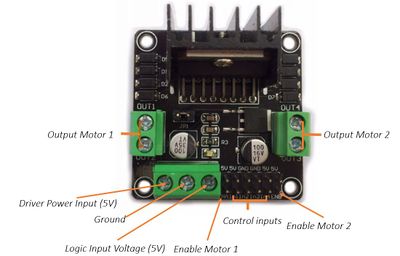
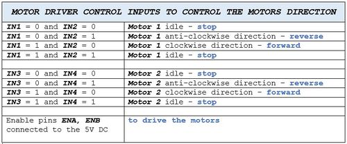
The DC motors are connected to the wheels which are in contact with the base of the ball. The DC motors are driven by a driver module which controls the motor direction and speed.
- Servo Motors
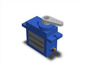
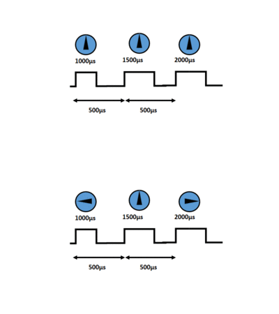
LS-0009AF Servo motor used is controlled by sending an electrical pulse of variable width or pulse width modulation (PWM), through the control wire. Maximum deflection which can be achieved by using this servo is 90°.The motor's neutral position is defined as the position where the servo has the same amount of potential rotation in the both the clockwise or counter-clockwise direction. The PWM sent to the motor determines the position of the shaft, and based on the duration of the pulse sent via the control wire; the rotor will turn to the desired position. The servo motor expects to see a pulse every 2000 microseconds and the length of the pulse will determine how far the motor turns. For example, a 1500microseconds pulse will make the motor turn to the 45° position. Shorter than 1500microseconds moves it in the counter-clockwise direction toward the 0° position, and any longer than 1500microseconds will turn the servo in a clockwise direction toward the 90° position.
The hardware implementation of how the DC motors are connected to the wheels which are driven from the SJOne board and how the servo motor is connected with the pendulum to steer the robot in right or left direction can be viewed in the figure below.
GPS module
In the project, we use GPS module Sparkfun Venus638FLPx to log the current location of the robot. An antenna is connected to the SMA connector of the GPS module. The software Skytraq GPS viewer is used to configure it. The module is configured to send information in NMEA message format (using the GPGGA (Global Positioning System Fix Data). We configured it to run at a baud rate of 38400bps and update rate of 2 Hz.
There are three modes of operation:
1. Hot Start: This enables the GPS to obtain a fix in a very less time if it is connected to a 3.3v coin cell battery and it is switched on again within two hours after switching it off. Connecting the battery will help it to store information about the previous fix.
2. Warm Start: In this mode, it will take the GPS more time to obtain a fix compared to the hot start as the module has been switched off for more than hours. But as the battery is connected and the information of the previous fix is available it will take less time compared to the cold start.
3. Cold Start: As the battery is not connected and information about the previous fix is not available in this mode, it will take a lot of time to obtain a fix.
In our project, we have connected a 3V external battery (VBAT) to the module so that it does not take a long time to get a satellite fix even after turning off and on.
The NMEA message looks as follows:
 GGA - Global Positioning System Fix Data :   $GPGGA,hhmmss.sss,ddmm.mmmm,a1,dddmm.mmmm,a2,V,xx,x.x,x.x,M,,,,xxxx*hh<CR><LF>

 where,
       Time              - hhmmss.sss
       Latitude          - ddmm.mmmm
       Direction         - (a1) - N or S
       Longitude         - dddmm.mmmm
       Direction         - (a2) - E or W
       Validity          - V - 0 or 1. 0 means invalid and 1 means valid.
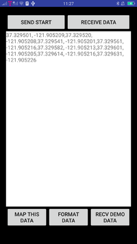
After this data is received by the SJOne board, string manipulation is done to extract the latitude and longitude from the string (if the data is valid) and they are converted to decimal minutes so that they can be sent to an android application where they are plotted on a map.
Bluetooth module
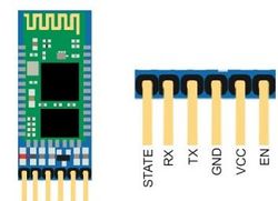
Bluetooth module HC-05 is used to communicate between the spherical robot and mobile application. It is implemented to establish the connection between the two so that we can remotely control the robot (to send start and stop signals) and receive the data from the robot directly on the Android application. The data being sent by the robot is current GPS location, ultrasonic range sensor values, and temperature sensor values.
Hardware Interface
We have four major hardware modules interfaced with a single SJOne board using different communication protocols. For simplicity sake, we have given a description of how each module is individually interfaced with the SJOne board. In reality, all these modules are connected to a single SJOne microcontroller.
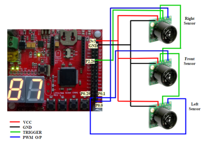
Ultrasonic Range Finders
The ultrasonic range finders have been interfaced with the SJOne board using PWM. To avoid the crosstalk between the sensors and to improve the efficiency, sensors are configured to work in chaining mode. In our project, the Right sensor is triggered first by holding the RX pin high for >20μs and < 48ms.This will start the sensor chain. The Right sensor will range, then trigger the Front sensor to the range which in turn trigger the last Left sensor.
Motors
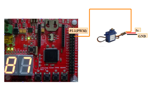
The DC motor is connected with the SJOne board via the motor driver module using GPIO. The GPIO signals from SJOne board provide inputs to the motor driver module, which in turn drives the DC motors in forward or reverse direction or stop signal. Servo motor is interfaced with the SJOne board using PWM.
GPS Module
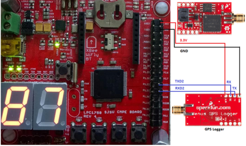
GPS module communicates with SJOne board via UART. The antenna is connected to the SM connector of the GPS module. A 3.3v supply is given to the module and its Rx and Tx pins are connected to the Tx and Rx pins of the SJOne board respectively. UART 2 of the SJOne board is used for the GPS module and it is configured to run at a baud rate of 38400bps.
Bluetooth module
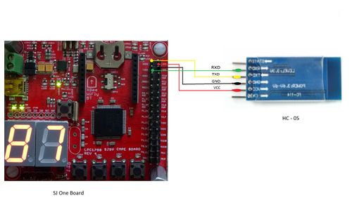
The Bluetooth HC-05 module is connected with the SJOne board via UART communication.The bluetooth module communicates using the Tx and Rx pins of HC-05. This device independently connects to any external bluetooth master device. The HC-05 can work as a Master or a Slave. For our application the device sends the GPS data from SD card and also receive data from Android Application. Since the device can be connected independently without the MCU it can be connected and used with MCU restarting and not affecting the connectivity. UART3 is used for serial communication. The Baud rate set is 9600 for communication between bluetooth device and Android Application.
Software Design
Ultrasonic Range Finder and Motors
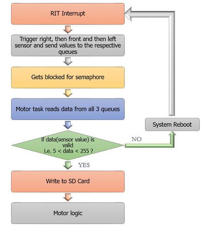
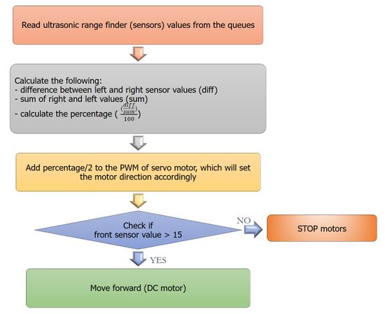
The motors working depends on the input values of sensors (ultrasonic range finders). Depending on whether the sensors can detect an obstacle in its path, the motors continue to run in the forward direction or the servo motor steers the robot towards right or left. The diagrams below shows the algorithm of the logic behind it.
GPS module
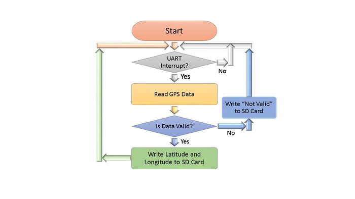
The GPS-SJOne board communication is done via UART. Whenever data is received by the SJOne board from the GPS module, a UART interrupt occurs and the data is stored in a buffer. The data is checked if it is valid or not. If it is valid, the latitude and longitude are written to the SDCard. Otherwise, it is written that no GPS signal was available at that point. The flowchart is shown below.
PCB Design
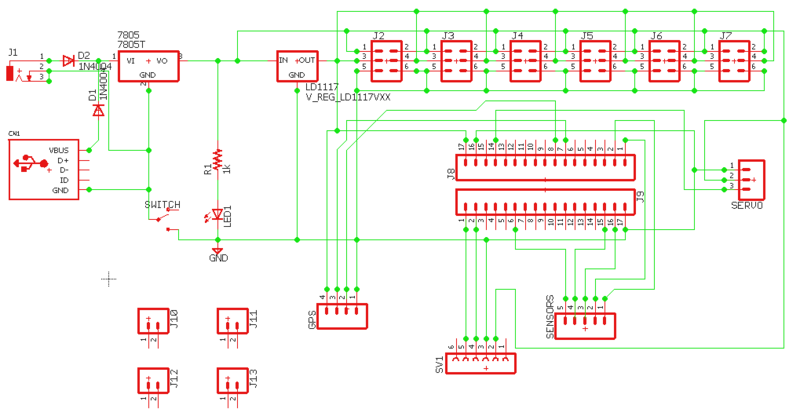
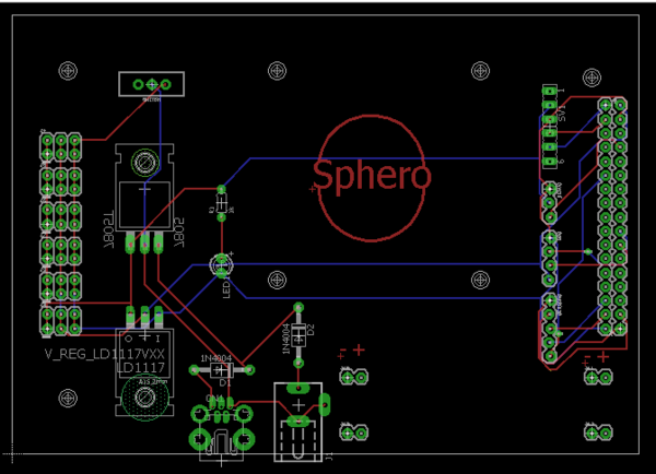
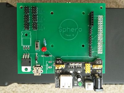
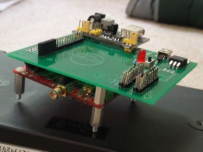
We have used EAGLE software to design the PCB layout. The PCB layout is the most crucial part of the project, it may make or break the performance and working of the circuit. The first step towards designing the PCB is including all the required components into the schematic workspace and making connections between them. Once the schematic is ready, next step is to create the board layout from the schematic, which is easy, since EAGLE links the layout file and schematic together automatically.
SD Card Writing
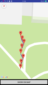
The data from the GPS, temperature sensor, accelerometer and ultrasonic range finders is continuously being logged onto an SDCard. The purpose of this is to send the data to a remote location once the robot's exploration is complete. In our case, we are reading the data from the SDCard and sending it to a mobile application. The mobile application will receive the latitude and longitude values and will plot a path on a map connecting the geographical locations the robot has visited. Screenshots of the data being logged are shown in the following figures. It can be observed that different GPS locations are being logged onto the SDCard as the robot travels.
Android Application
The Android Application development was divided into multiple stages:
1. Building the first App with interactive buttons
2. Communicating with Bluetooth module, hence tried and used many approaches.
3. Sending and Receiving data between Activities within Android App
4. Transmission and Reception of data from bluetooth device connected to SJ One board.
5. Plotting the data on Google Maps using google maps API.
Testing & Technical Challenges
1. Incorrect sensor values at different voltage levels - This was solved by providing stable IC output at 3.3V.
2. Unbalanced weight distribution and unstable platform - Because of unbalanced weight distribution, the sensors platform connected to the axle was unstable while running. This solved by changing the hardware positioning internally.
3. Abnormal restart of the microcontroller when motors begin - This was solved by providing sufficient power supply and running all modules on single voltage of 3.3V
4. Problem in steering the robot - This issue was solved by increasing the weight connected to the servo motor and the length of the pendulum.
5. Difficulty in finding the end of file while reading from the SD Card - A special character was used to while writing into the file to indicate the end of the file.
6. Unable to read corrupted SD card - On starting the robot, we first validate if the SD card is ready to communicate using sd_initialize(), and if not, then the robot will not respond to start from the application.
7. Initially, we had to dismantle the robot every time and remove the internal modules to restart the robot - We avoided this by using a volatile variable that is sent from the android application. The low priority task that runs will check if the variable has changed, and if changed then it will restart.
Conclusion
We have successfully designed and implemented an autonomous spherical robot. This project has helped us understand the implementation of FreeRTOS concepts like prioritizing tasks and using semaphore and mutex for SD card reading and writing. We learned to implement our own communication protocol drivers such as UART and I2C. Even though the hardware implementation was tedious and challenges like unbalanced weight distribution and unstable platform took some time to resolve, it was all an overwhelming learning experience.
Project Video
1. Final project video - https://youtu.be/8crZVj166tY
2. Sensor and motor testing - https://youtu.be/_Tye2R-DpHY
3. First Indoor run (checking mechanical structure) - https://youtu.be/JykHXq53Ipg
4. Steering of the robot using pendulum with the servo motor - https://youtu.be/N-BSanpUjbk
Project Source Code
References
Acknowledgement
We would like to thank Prof. Preetpal Kang for encouraging us and guiding us throughout the semester. We are grateful to you for making this class such a valuable learning experience for us. We would also like to thank the ISA members who have been there to help us and for being approachable anytime.
References Used
[1] CMPE 244 Lecture notes from Preetpal Kang, Computer Engineering, San Jose State University. Jan-May 2017.
[2] Android & Java Forums(www.stackoverflow.com)
[3] Android References (Developer Android)
[4] MaxSonar datasheet
[5] Bluetooth Module HC-05
[6] GPS Visualizer
[7] A literature review on the design of spherical rolling robots by V. Crossley
[8] Datasheet for the Venus GPS Module
