Difference between revisions of "F19: Tower Defense in Space"
Proj user10 (talk | contribs) (→RGB LED Matrix) |
(→Grading Criteria) |
||
| (144 intermediate revisions by one other user not shown) | |||
| Line 1: | Line 1: | ||
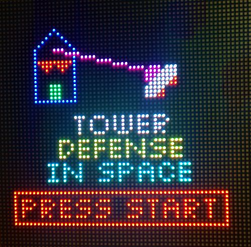
[[File:start_menu.jpg|thumb|500px|caption|right|Logo]] | [[File:start_menu.jpg|thumb|500px|caption|right|Logo]] | ||
| − | === | + | == Abstract== |
| − | + | This project involves creating and developing a video game where output is displayed on a LED matrix. Development of the relevant hardware/software components and modules was divided among 4 team members. Each team member lead or significantly contributed to the development of multiple components. The project was focused on not only technical skills, but team building as well, and working with others towards a common goal. | |
| − | |||
| − | |||
| − | |||
| − | |||
| − | |||
| − | |||
| − | |||
| − | |||
| − | |||
| − | |||
| − | |||
| − | |||
| − | + | This project provides us hands-on experience using freeRTOS in a real application. Our objective is to apply what we have learned in class and develop a video game using our SJtwo Board. In this project, we create different tasks for different modules, such as a display task for displaying the game objects on LED matrix, a tower task for detecting nearby enemies and shoot them, a stage task to manage each game stage etc. We need to use both cooperative scheduling and preemptive scheduling technique to make this video game run efficiently. In order to make this game run in a particular sequence, we also need to synchronize and sequentialize each task by setting the task priorities carefully and using binary semaphore correctly. <br /> | |
| − | |||
<br /> | <br /> | ||
== Introduction and Objectives == | == Introduction and Objectives == | ||
| − | + | [[File:AlienInvasion.jpeg|300px|thumb|right|Alien Invasion]] | |
| + | Like most traditional tower defense games, the player needs to defend our planet from the invasion of aliens. The gameplay can be split into 2 phases, <b>Combat Phase</b> and <b>Intermission Phase</b>. During the intermission phase, the player can place different kinds of towers strategically that will attack the invading aliens from entering into our homeland by shooting the enemies. During the combat phase, spaceships follow the path and try to land on our planet. If any enemy spaceship reaches the end of the path, then the player loses. If there are no more spaceships remaining in a wave, the player can build a stronger tower that has a longer attack range and can shoot a more powerful laser to the spaceships in the next wave. The player wins the game after surviving 5 waves of attack. | ||
| − | + | This game can be separated into 4 different modules: | |
| − | + | #<b>Game Logic</b>: SJtwo Board - handles the game logic. (For example: detect and shoot nearby enemies, switch between intermission phase and combat phase) | |
| − | + | #<b>Display</b>: Adafruit 64x64 LED matrix - displays the animation of the game. | |
| + | #<b>Gamepad Controller</b>: The input of this game. The gamepad controller consists of a joystick and two buttons. The player can use the joystick to move the cursor and decide where to place the towers. After that, the user needs to press the black button to select and confirm the location of the towers. If the player knows that he/she has made a mistake in the middle of the game and will eventually lose the game, the player can press the red button and restart the game. | ||
| + | #<b>Sound</b>: MP3 Decoder and speaker. Players can enjoy cool music during the game. This is done on an additional SJtwo board, which will play the song on repeat. | ||
== Team Members == | == Team Members == | ||
| Line 420: | Line 410: | ||
== Game Design == | == Game Design == | ||
| + | === <font color="000000"> Game Rules </font> === | ||
| + | Gameplay is split into 2 phases: <br> | ||
| + | <b>Intermission</b> - Player sets up tower locations <br> | ||
| + | <b>Combat</b> - Player watches round unfold <br> | ||
| − | === <font color="000000"> | + | During the <b>Intermission Phase</b>: <br> |
| + | #The player places towers strategically around the enemy path. <br> | ||
| + | #The number of towers is fixed per round <br> | ||
| + | #Towers can only be placed in marked areas that do not lie on a path <br> | ||
| + | #The built-in software will find a valid tower location and move the cursor there automatically according to joystick input. <br> | ||
| + | #There are 5 types of towers (increasing damages, ranges, and of different colors). Each tower type depends on the current wave.<br> | ||
| + | |||
| + | During the <b>Combat Phase</b>: <br> | ||
| + | #Enemies will enter the gameplay area at one end of the path and attempt to reach the other end <br> | ||
| + | #Towers will automatically engage enemies when they come within range <br> | ||
| + | #Towers shoot until the enemy is either dead or out of range <br> | ||
| + | #Tower proximity is 8 directions (top, bot, left, right, top-right, top-left, bot-left, bot-right) and 1 unit (not necessarily 1 pixel) away <br> | ||
| + | #Enemies that reach the end of path while being alive will result in losing the game. <br> | ||
| + | #If any spaceship reaches the end of the path, the player loses and the game ends <br> | ||
| + | #The round is over when the player loses or a set number of enemies have been defeated. <br> | ||
| + | <br> | ||
| + | |||
| + | [[File:combatPhase_0.JPG|300px|thumb|right|Dashboard (Combat Phase)]] | ||
| + | |||
| + | There will be a <b>dashboard</b> on the LED matrix that displays basic UI information: <br> | ||
| + | <b>Intermission Phase:</b> | ||
| + | #Time until combat phase <br> | ||
| + | #Current wave number <br> | ||
| + | #Number of towers left that you can still place <br> | ||
| + | <b>Combat Phase:</b> | ||
| + | #Current wave number <br> | ||
| + | #Number of enemies still remaining in the current wave<br> | ||
| + | |||
| + | === <font color="000000"> Game Objectives </font> === | ||
| + | #There are 5 waves (rounds) total. <br> | ||
| + | #In each round, enemies in various amounts, groupings, and health levels (armor) pass through the path. <br> | ||
| + | #If any enemies reach the end of the path, then the user loses. <br> | ||
| + | #After each round, the user will be able to place more towers which are stronger and can shoot farther. <br> | ||
| + | #Each round will have waves of enemies that are more difficult to stop. <br> | ||
| + | #The user needs to carefully place their towers such that it will have a maximum number of opportunities to shoot at the enemies. <br> | ||
| + | #The trick is that the user will need to preserve early level towers, otherwise they will not have enough room to place the high level towers in the optimal location. <br> | ||
=== <font color="000000"> How To Play </font> === | === <font color="000000"> How To Play </font> === | ||
| + | |||
| + | The gamepad controller consists of a joystick and two buttons. | ||
| + | *Joystick - move the cursor and decide where to place the towers. | ||
| + | *Black button - select and confirm the location of the towers. | ||
| + | *Red button - restart the game (If the player knows that he/she has made a mistake in the middle of the game and will eventually lose the game, the player can press the red button and restart the game.) | ||
| + | |||
| + | During the <b>Intermission Phase</b>: <br> | ||
| + | # The player places towers strategically around the enemy path by using the joystick to move the cursor and pressing the black button to select the location of the towers. | ||
| + | # The player needs to place all remaining towers under 45 seconds. | ||
| + | During the <b>Combat Phase</b>: <br> | ||
| + | # Cheer on your towers and watch them defend Earth from the alien invasion! | ||
== <font color="000000"> Hardware Design - Electrical </font> == | == <font color="000000"> Hardware Design - Electrical </font> == | ||
| Line 539: | Line 579: | ||
=== RGB LED MATRIX === | === RGB LED MATRIX === | ||
The LED matrix that we use is 64 pixels by 64 pixels and is controlled through a 12-pin header consisting of the following pins: | The LED matrix that we use is 64 pixels by 64 pixels and is controlled through a 12-pin header consisting of the following pins: | ||
| − | |||
*Five Mux pins (A,B,C,D,E) for Row Selection | *Five Mux pins (A,B,C,D,E) for Row Selection | ||
| Line 553: | Line 592: | ||
All these pins are required to display a specific color on a specific pixel of the LED matrix display. | All these pins are required to display a specific color on a specific pixel of the LED matrix display. | ||
| + | {| | ||
| + | |[[File:Pin assignment LED Matrix.jpg|500px|thumb|middle|Pin Connections between SJtwo Board and REG LED Matrix]] | ||
| + | |[[File:scan116.gif|200px|thumb|right|LED Matrix - Row Scanning]] | ||
| + | |} | ||
| − | + | Apparently, it is impossible to driver all 4096 LEDs all at one time and thus, we can only drive two rows of LEDs at a time (one row on the upper half of the display and another row on the lower half of the display). By refreshing the LED matrix two rows at a time in a fast frequency, we can display all the game objects with animation on the LED matrix. | |
=== Joysticker controller === | === Joysticker controller === | ||
The joystick that we use is the product from Adafruit, the Analog 2-axis Thumb Joystick. This 2-axis Thumb Joystick provides the following pins: | The joystick that we use is the product from Adafruit, the Analog 2-axis Thumb Joystick. This 2-axis Thumb Joystick provides the following pins: | ||
| − | # | + | # Two ADC pins |
## In order to control the tower location, we need to control the Joysticker, since the direction has four: Up, Down, Left, Right, we use the Y and X-axis to implement this function. | ## In order to control the tower location, we need to control the Joysticker, since the direction has four: Up, Down, Left, Right, we use the Y and X-axis to implement this function. | ||
| − | # Three GPIO | + | # Three GPIO pins |
## In order for selecting for the tool we need two GPIO pin for button and 1 GPIO pin for controlling the LED on the JOY STICKER controller | ## In order for selecting for the tool we need two GPIO pin for button and 1 GPIO pin for controlling the LED on the JOY STICKER controller | ||
| + | |||
| + | * Pin configuration | ||
| + | [[File:Selection 999(032).png]] | ||
=== MP3 Decoder === | === MP3 Decoder === | ||
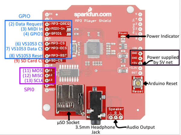
The MP3 decoder that we use is Sparkfun’s vs1053 shield MP3 decoder which is the board based on the vs1053b chip. | The MP3 decoder that we use is Sparkfun’s vs1053 shield MP3 decoder which is the board based on the vs1053b chip. | ||
| + | |||
| + | {| | ||
| + | |[[File:MP3DECODER PON.png|600px|thumb|left|MP3 Decoder Module Pinout]] | ||
| + | |} | ||
{| | {| | ||
| − | |[[File: | + | |[[File:Selection 999(034).png|600px|thumb|left|MP3 Decoder Pin Table]] |
| − | |||
|} | |} | ||
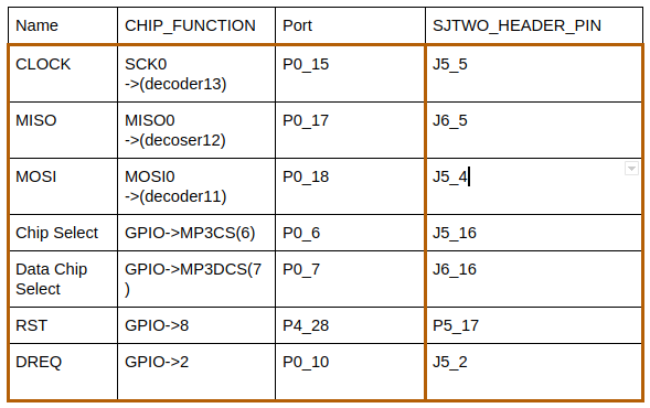
| + | * Three SPI pin | ||
| + | In order to communicate with the mp3 decoder with SJtwo Board, we choose the SPI as the protocol to control the decoder. Hence, we need the one pin SCK0 | ||
| + | (clock), one pin MOSI(Master In Slave Out) and one pin (Master Out Slave In). | ||
| + | * Four GPIO pin for the decoder | ||
| + | There are four major GPIO pin for DREQ(Data Request Pin), Reset, CS(Chip Select), XDCS(Data Chip Select), this 4 GPIO pin is how we transfer data and send | ||
| + | the command to activate the mp3 decoder work with SJ2 Board. | ||
== <font color="000000"> Software Design </font> == | == <font color="000000"> Software Design </font> == | ||
| Line 578: | Line 633: | ||
All the LED Matrix data are stored in a buffer with its size equal to 32 by 64. Each element in this buffer store the color of two pixels, one pixel from the upper half of the display and one pixel from the lower half of the display. | All the LED Matrix data are stored in a buffer with its size equal to 32 by 64. Each element in this buffer store the color of two pixels, one pixel from the upper half of the display and one pixel from the lower half of the display. | ||
| − | In order to display the gaming objects in animation, we need to refresh the display by displaying the color pixels on each row one by one. Below is a | + | In order to display the gaming objects in animation, we need to refresh the display by displaying the color pixels on each row one by one very fast. Below is a simple flowchart that describes the process of refreshing the display. |
* Loop through each row of the LED display | * Loop through each row of the LED display | ||
| − | # Select Row (By controlling the output level of 5 mux pins, we can select one row at | + | # Select Row (By controlling the output level of 5 mux pins, we can select one row at a time) |
# Disable the LED Display output (Turn off the LEDs of the current row of the display) | # Disable the LED Display output (Turn off the LEDs of the current row of the display) | ||
# Unlatch the Data | # Unlatch the Data | ||
| Line 590: | Line 645: | ||
# Delay for a 100us (Increase the light intensity of the LEDs by delay a short amount of time) | # Delay for a 100us (Increase the light intensity of the LEDs by delay a short amount of time) | ||
# Disable the LED Display output (Turn off the LEDs of the current row of the display) | # Disable the LED Display output (Turn off the LEDs of the current row of the display) | ||
| − | [[File:RefreshDisplaySequence.jpg| | + | |
| + | <syntaxhighlight lang="c"> | ||
| + | void refreshDisplay(void) { | ||
| + | for (uint8_t row = 0; row < LEDMATRIX_HALF_HEIGHT; row++) { | ||
| + | |||
| + | select_row(row); | ||
| + | led_matrix__disable_output(); // gpio__set(OE); | ||
| + | led_matrix__unlatch_data(); // gpio__set(LAT); | ||
| + | led_matrix__clock_in_data(row); | ||
| + | led_matrix__latch_data(); // gpio__reset(LAT); | ||
| + | led_matrix__enable_output(); // gpio__reset(OE); | ||
| + | delay__us(100); // Change Brightness | ||
| + | led_matrix__disable_output(); | ||
| + | } | ||
| + | } | ||
| + | </syntaxhighlight> | ||
| + | |||
| + | <syntaxhighlight lang="c"> | ||
| + | void led_matrix__clock_in_data(uint8_t row) { | ||
| + | /* Clock in data for each column */ | ||
| + | for (uint8_t col = 0; col < LEDMATRIX_WIDTH; col++) { | ||
| + | |||
| + | /* Set all the RGB pins as low*/ | ||
| + | LPC_GPIO1->PIN &= ~(0x1 << R1.pin_number | 0x1 << G1.pin_number | 0x1 << B1.pin_number); | ||
| + | LPC_GPIO2->PIN &= ~(0x1 << R2.pin_number | 0x1 << G2.pin_number | 0x1 << B2.pin_number); | ||
| + | |||
| + | /* Set the RGB pins as High or Low depends on the data stored inside the buffer */ | ||
| + | LPC_GPIO1->PIN |= ((((display_matrix[row][col] >> 0) & 0x1) << R1.pin_number) | | ||
| + | (((display_matrix[row][col] >> 1) & 0x1) << G1.pin_number) | | ||
| + | (((display_matrix[row][col] >> 2) & 0x1) << B1.pin_number)); | ||
| + | |||
| + | LPC_GPIO2->PIN |= ((((display_matrix[row][col] >> 4) & 0x1) << R2.pin_number) | | ||
| + | (((display_matrix[row][col] >> 5) & 0x1) << G2.pin_number) | | ||
| + | (((display_matrix[row][col] >> 6) & 0x1) << B2.pin_number)); | ||
| + | |||
| + | gpio__set(CLK); | ||
| + | gpio__reset(CLK); | ||
| + | } | ||
| + | } | ||
| + | </syntaxhighlight> | ||
| + | |||
| + | {| | ||
| + | |[[File:RefreshDisplaySequence.jpg|300px|Process of refreshing display]] | ||
| + | |} | ||
| + | === <font color="000000"> MP3 Decoder </font> === | ||
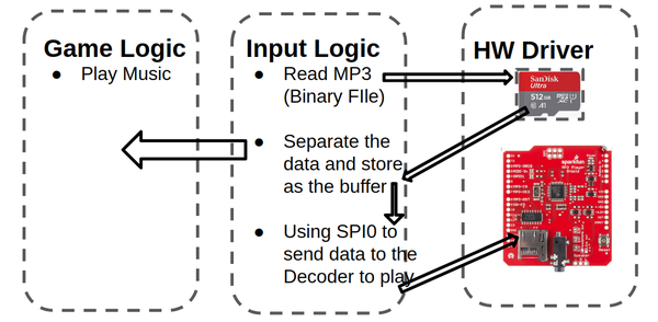
| + | The MP3 deocder is executed with the mainly two task: read task and play task. | ||
| + | The reader task would read data from the sd card and sned queue data for the player task to play music. | ||
| + | |||
| + | {| | ||
| + | |[[File:MP3DECODERMODULE.png|600px|thumb|left|MP3 Decoder Module API]] | ||
| + | |} | ||
| + | * Read Task | ||
| + | * Loop through each row of the LED display | ||
| + | # Queue sned the target filename | ||
| + | # Queue receive the target name | ||
| + | # Find the mp3 file name is exit or not | ||
| + | # Open the file(fopen) | ||
| + | # Read data store to the buffer(Binary) | ||
| + | # Sent the data from bufder with queuesend API | ||
| + | |||
| + | {| | ||
| + | |[[File: READ TASK.png]] | ||
| + | |} | ||
| + | |||
| + | * Play Task | ||
| + | Receive the data of the song from the queue, and use the receiving data and sent the command to make decoder to play music. | ||
| + | |||
| + | * Read Task | ||
| + | * Loop through each row of the LED display | ||
| + | # Queue receive the data(music) | ||
| + | # disable the chip select | ||
| + | # Check the DREQ pin to know is ready or not | ||
| + | # exchange the data to the decoder to play the music | ||
| + | # Check the DREQ pin to know is ready or not | ||
| + | # disable the chip select | ||
| + | {| | ||
| + | |[[File: Play Task.png]] | ||
| + | |} | ||
=== <font color="000000"> JOY STICKER </font> === | === <font color="000000"> JOY STICKER </font> === | ||
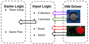
| Line 607: | Line 739: | ||
{| | {| | ||
| − | |[[File:Joystickermodule.png| | + | |[[File:Joystickermodule.png|1000x|thumb|left|Game controller]] |
|} | |} | ||
| Line 615: | Line 747: | ||
=== <font color="000000"> System Flow Charts </font> === | === <font color="000000"> System Flow Charts </font> === | ||
| + | <br> | ||
| + | <b> Basic Software Environment: </b> <br> | ||
| + | [[File:Flow1 TDIS.png]] | ||
| + | |||
| + | <br> | ||
| + | <b> Game Master (how the user sees the game flowing): </b> <br> | ||
| + | [[File:Flow2_TDIS.png]] | ||
| + | |||
| + | <br> | ||
| + | <b> Intermission Phase (what happens while the user is placing towers): </b> <br> | ||
| + | [[File:Flow3_TDIS.png]] | ||
| + | |||
| + | <br> | ||
| + | <b> Combat Phase (what happens when the aliens invade): </b> <br> | ||
| + | [[File:Flow4_TDIS.png]] | ||
== <font color="000000"> System Testing and Validation </font> == | == <font color="000000"> System Testing and Validation </font> == | ||
| + | {| | ||
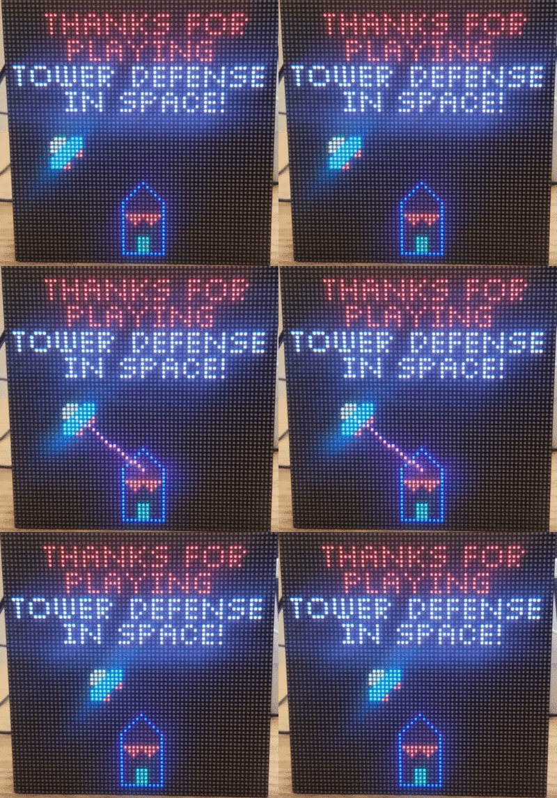
| + | |[[File:StartScreenTowerDefense.gif|400px|thumb|left|Start Screen]] | ||
| + | |[[File:CombatPhase.gif|400px|thumb|left|Combat Phase]] | ||
| + | |} | ||
| + | {| | ||
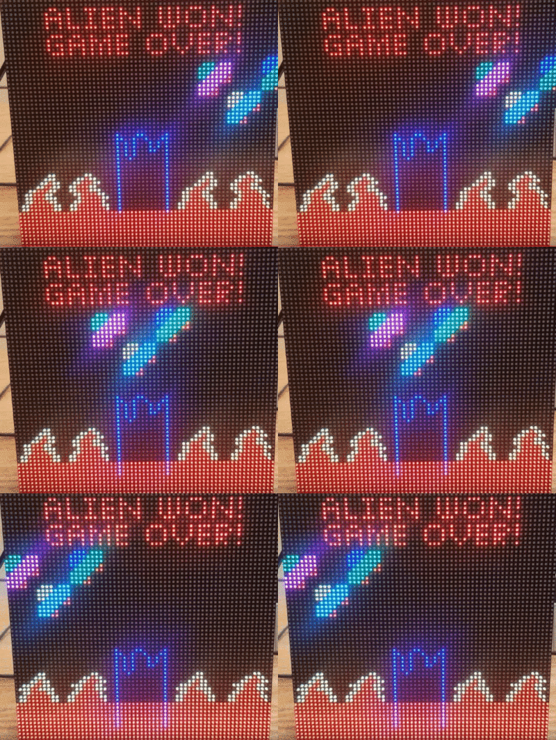
| + | |[[File:EndGame.gif|400px|thumb|left|Player Loses the game]] | ||
| + | |[[File:VictoryScreen TowerDefense.gif|400px|thumb|left|Player Wins the game]] | ||
| + | |} | ||
== <font color="000000"> Technical Challenges </font> == | == <font color="000000"> Technical Challenges </font> == | ||
| + | |||
| + | === Game Map (2D array) to LED matrix (2D pixels) Conversion === | ||
| + | Issue: | ||
| + | # The game map (consisting of the path as well as all of the active enemies and towers) is managed through the use of a 2D char array. | ||
| + | # In order to display each object on the LED matrix, there needs to be a mechanism that converts the object along with its 2D array location to a row/column on the LED matrix. | ||
| + | # An algorithm to do this conversion is not as straightforward as it may appear. This is because objects stored in the array take up more/less display space than what is available on the LED matrix. | ||
| + | Solution: | ||
| + | # In order to align the array locations with the LED matrix pixel locations, some areas on the 2D array needed to be marked as "ignore". <br> | ||
| + | # If each array location is not carefully correlated to a specific pixel location, then there would be issues where objects are displayed overlapping each other on the LED matrix (or simply displayed in the wrong spot). | ||
| + | # There were some simple algorithms that used math to help implement this conversion. <br> | ||
| + | # However, a LUT is what was primarily used. It was not efficient in terms of code size, it took over 500 lines of code. <br> | ||
| + | # But it was an effective solution and allowed us to easily decide exactly where each pixel of each object would be displayed. | ||
| + | |||
=== LED Matrix Flickering Issue === | === LED Matrix Flickering Issue === | ||
| − | Issue: While we are developing the game, we notice that some color pixels are | + | Issue: While we are developing the game, we notice that some color pixels are turned on when they are supposed to be off. |
| − | Solution: | + | Investigation/Solution: |
| − | # | + | # See [[Known Breakout PCB Issues]] as a possible cause. It's possible the SJTWO board is getting inconsistent power. |
| − | # | + | # Refreshing the matrix should not be handled by an interrupt and not a task. The task should only push new display data and not have direct control of the matrix. Keeping the refresh interrupt driven would keep the refresh rate more consistent by removing the process being context switched out mid update. |
=== MP3 Decoder - SJtwo Board SPI Selection === | === MP3 Decoder - SJtwo Board SPI Selection === | ||
| Line 633: | Line 801: | ||
# It's hard to know the configuration is successful or not. | # It's hard to know the configuration is successful or not. | ||
Solution: | Solution: | ||
| − | # Doing the survey on the GitHub is really important. For example, using the sin wave and hello binary example to test how the Initialization and HZ parameter would save a lot of time. | + | # Doing the survey on the GitHub is really important. For example, using the sin wave and hello binary example to test how the Initialization and HZ parameter would save a lot of time.Moreover, in the document from the vs1053b, we could use the binary file line "hello", "sine wave" function for testing. |
# Besides, we also have to be careful to check the SJBoard's SPI because of the SD card reader is using for reading SDcard. Hence, I would recommend using other | # Besides, we also have to be careful to check the SJBoard's SPI because of the SD card reader is using for reading SDcard. Hence, I would recommend using other | ||
SPI0, SPI1 instead of using SPI2. | SPI0, SPI1 instead of using SPI2. | ||
== <font color="000000"> Conclusion </font> == | == <font color="000000"> Conclusion </font> == | ||
| − | + | We successfully designed and implemented the video game "Tower Defense In Space". All of our team members now have a better understanding of how to use FreeRTOS to handle the synchronization of multiple tasks and to communicate with multiple hardware components in an embedded application system. After completing this project, we learned how to manage a project on a tight schedule. Starting from purchasing hardware components, developing hardware drivers and game logic and then integrating all of the drivers and APIs into the game logic. Furthermore, all of us are now better at coding and debugging code. | |
| + | For a game design project like this, we learned that it's not always best to assign tasks independently between the team members. We learned that this type of project would benefit moreso from pair programming and other cooperative tasks that enable collaboration between teammates. Otherwise, project tasks may be done in such a way that they only work for 1 specific configuration, and wouldn't help progress towards the end goal of the integrated system. We also learned that not every day was going to be perfect, but as long as we never gave up and worked hard, then the final result would not be disappointing! | ||
| − | === <font color="000000"> Video Demonstration </font> | + | |
| + | We would like to say thank you to Prof. Preet and all the ISAs for their precious suggestions and assistance during the development of this project! | ||
| + | |||
| + | == Advice for Future Students == | ||
| + | |||
| + | ==== Source Control ==== | ||
| + | Unless everyone in your group is comfortable using source control, don't use it. It will likely end up costing you time in the long run. | ||
| + | |||
| + | ==== Start working on your LED Matrix driver ASAP ==== | ||
| + | The first 64x64 LED Matrix that we got from Sparkfun suffers from a serious flickering issue. After spending for a week trying to debug what causes the flickering issue, we still have no idea whether it is a hardware issue or software issue. Later, we borrow another LED matrix from a student of our class and test our code. With the other student's LED matrix (we use our own power supply and ribbon cables), there is no flickering issue at all. According to some online resources, some matrix vendors scatter the selected rows and columns differently. It is possible that your designed driver may only work on some LED matrix vendors' displays. | ||
| + | |||
| + | == <font color="000000"> Video Demonstration </font> == | ||
[https://www.youtube.com/watch?v=b2isxUJta6Q Demo Video (Player Wins)] | [https://www.youtube.com/watch?v=b2isxUJta6Q Demo Video (Player Wins)] | ||
[https://www.youtube.com/watch?v=fylwPk5g_3Q Demo Video (Player Loses)] | [https://www.youtube.com/watch?v=fylwPk5g_3Q Demo Video (Player Loses)] | ||
| − | + | == <font color="000000"> Source Code </font> == | |
| − | [https://gitlab.com/rollin_nolan/tower-defense-in-space Tower_Defense_In_Space_Gitlab] | + | * [https://gitlab.com/rollin_nolan/tower-defense-in-space Tower_Defense_In_Space_Gitlab] |
| − | + | * [https://drive.google.com/file/d/1kggWmH2kcPciE4tFG8gYCbF9gfV2dXkk/view zip file (must have SJSU email address)] | |
| − | |||
| − | |||
| − | |||
Latest revision as of 23:33, 21 December 2019
Contents
- 1 Abstract
- 2 Introduction and Objectives
- 3 Team Members
- 4 Schedule
- 5 Bill of Materials
- 6 Game Design
- 7 Hardware Design - Electrical
- 8 Hardware Design (Mechanical)
- 9 Hardware Integration
- 10 Software Design
- 11 System Testing and Validation
- 12 Technical Challenges
- 13 Conclusion
- 14 Advice for Future Students
- 15 Video Demonstration
- 16 Source Code
Abstract
This project involves creating and developing a video game where output is displayed on a LED matrix. Development of the relevant hardware/software components and modules was divided among 4 team members. Each team member lead or significantly contributed to the development of multiple components. The project was focused on not only technical skills, but team building as well, and working with others towards a common goal.
This project provides us hands-on experience using freeRTOS in a real application. Our objective is to apply what we have learned in class and develop a video game using our SJtwo Board. In this project, we create different tasks for different modules, such as a display task for displaying the game objects on LED matrix, a tower task for detecting nearby enemies and shoot them, a stage task to manage each game stage etc. We need to use both cooperative scheduling and preemptive scheduling technique to make this video game run efficiently. In order to make this game run in a particular sequence, we also need to synchronize and sequentialize each task by setting the task priorities carefully and using binary semaphore correctly.
Introduction and Objectives
Like most traditional tower defense games, the player needs to defend our planet from the invasion of aliens. The gameplay can be split into 2 phases, Combat Phase and Intermission Phase. During the intermission phase, the player can place different kinds of towers strategically that will attack the invading aliens from entering into our homeland by shooting the enemies. During the combat phase, spaceships follow the path and try to land on our planet. If any enemy spaceship reaches the end of the path, then the player loses. If there are no more spaceships remaining in a wave, the player can build a stronger tower that has a longer attack range and can shoot a more powerful laser to the spaceships in the next wave. The player wins the game after surviving 5 waves of attack.
This game can be separated into 4 different modules:
- Game Logic: SJtwo Board - handles the game logic. (For example: detect and shoot nearby enemies, switch between intermission phase and combat phase)
- Display: Adafruit 64x64 LED matrix - displays the animation of the game.
- Gamepad Controller: The input of this game. The gamepad controller consists of a joystick and two buttons. The player can use the joystick to move the cursor and decide where to place the towers. After that, the user needs to press the black button to select and confirm the location of the towers. If the player knows that he/she has made a mistake in the middle of the game and will eventually lose the game, the player can press the red button and restart the game.
- Sound: MP3 Decoder and speaker. Players can enjoy cool music during the game. This is done on an additional SJtwo board, which will play the song on repeat.
Team Members
|
TEAM MEMBERS & RESPONSIBILITIES | ||||
|---|---|---|---|---|
|
Team Members |
Administrative Roles |
Technical Roles | ||
|
Team Lead |
| ||
|
Git Repo Manager |
| |||
|
Wiki Report Manager |
| ||
|
Bill of Materials Manager |
| ||
Schedule
|
TEAM MEETING DATES & DELIVERABLES | ||||
|---|---|---|---|---|
|
Week# |
Date Assigned |
Deliverables |
Status | |
| 1 | 10/15/19 |
|
| |
| 2 | 10/22/19 |
|
| |
| 3 | 10/29/19 |
|
| |
| 4 | 11/5/19 |
Kelvin
|
| |
| 5 | 11/12/19 |
Kelvin
Polin
Ryan
Zach
|
| |
| 6 | 11/19/19 |
Kelvin
Polin
Ryan
Zach
|
| |
| 7 | 11/26/19 |
Kelvin
Polin
Ryan
Zach
|
| |
| 8 | 12/3/19 |
|
| |
| 9 | 12/10/19 |
|
| |
Bill of Materials
|
Top Level | ||||
|---|---|---|---|---|
|
PART NAME |
PART MODEL & SOURCE |
QUANTITY |
COST PER UNIT (USD) | |
| |
|
|
| |
| |
|
|
| |
| |
|
|
| |
| 64x64 RGB LED Matrix* | Adafruit | 1 | $104.07 | |
| 5V 4A PSU | - | 1 | FREE | |
|
Breakout Board PCB** | ||||
|---|---|---|---|---|
|
Item # |
PART NAME |
PART SOURCE |
QUANTITY |
COST PER UNIT (USD) |
| 1 | IC REG LINEAR LD1117S33CTR | DIGIKEY | 5 | $0.351 |
| 2 | MHS16N-ND 16POS CONN 2.54MM | DIGIKEY | 2 | $2.60 |
| 3 | CAP CER 0.1UF 25V X7R 1206 | DIGIKEY | 5 | $0.221 |
| 4 | CAP CER 10UF 16V X5R 1206 | DIGIKEY | 5 | $0.202 |
| 5 | RES SMD 470 OHM 1% 1/4W 1206 | DIGIKEY | 10 | $0.0267 |
| 6 | PTC RESET FUSE 24V 500MA 1206 | DIGIKEY | 10 | $0.1588 |
| 7 | CONN SOCKET 40POS 0.1 TIN PCB | DIGIKEY | 2 | $5.03 |
| 8 | Manufacturing x 5 boards * | JLCPCB | 1 | $29.81 |
|
Gamepad PCB** | ||||
|---|---|---|---|---|
|
Item # |
PART NAME |
PART SOURCE |
QUANTITY |
COST PER UNIT (USD) |
| 1 | Analog 2-axis Thumb Joystick w/ select button | Amazon | 1 | $7.67 |
| 2 | SAM8205-ND 10POS 1.27MM | DIGIKEY | 5 | $3.38 |
| 3 | LED GREEN 1206 SMD | DIGIKEY | 5 | $0.24 |
| 4 | LED RED 1206 SMD | DIGIKEY | 5 | $0.257 |
| 5 | RES 1K OHM 1% 1/2W 1206 SMD | DIGIKEY | 5 | 0.0358 |
| 6 | CAP CER 0.1UF 50V X7R 1206 | DIGIKEY | 5 | $0.088 |
| 7 | 12x12x7.3mm Tactile Push Button w/ cap (pack of 25) | Amazon | 1 | $7.89 |
| 8 | Manufacturing x 5 boards * | JLCPCB | 1 | $14.21 |
* Shipping and tax included in value shown in the cost per unit column
** Only parts that were purchased are displayed.
Game Design
Game Rules
Gameplay is split into 2 phases:
Intermission - Player sets up tower locations
Combat - Player watches round unfold
During the Intermission Phase:
- The player places towers strategically around the enemy path.
- The number of towers is fixed per round
- Towers can only be placed in marked areas that do not lie on a path
- The built-in software will find a valid tower location and move the cursor there automatically according to joystick input.
- There are 5 types of towers (increasing damages, ranges, and of different colors). Each tower type depends on the current wave.
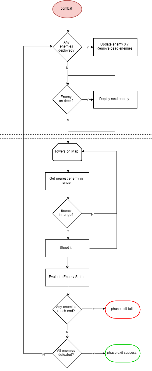
During the Combat Phase:
- Enemies will enter the gameplay area at one end of the path and attempt to reach the other end
- Towers will automatically engage enemies when they come within range
- Towers shoot until the enemy is either dead or out of range
- Tower proximity is 8 directions (top, bot, left, right, top-right, top-left, bot-left, bot-right) and 1 unit (not necessarily 1 pixel) away
- Enemies that reach the end of path while being alive will result in losing the game.
- If any spaceship reaches the end of the path, the player loses and the game ends
- The round is over when the player loses or a set number of enemies have been defeated.
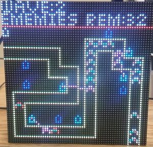
There will be a dashboard on the LED matrix that displays basic UI information:
Intermission Phase:
- Time until combat phase
- Current wave number
- Number of towers left that you can still place
Combat Phase:
- Current wave number
- Number of enemies still remaining in the current wave
Game Objectives
- There are 5 waves (rounds) total.
- In each round, enemies in various amounts, groupings, and health levels (armor) pass through the path.
- If any enemies reach the end of the path, then the user loses.
- After each round, the user will be able to place more towers which are stronger and can shoot farther.
- Each round will have waves of enemies that are more difficult to stop.
- The user needs to carefully place their towers such that it will have a maximum number of opportunities to shoot at the enemies.
- The trick is that the user will need to preserve early level towers, otherwise they will not have enough room to place the high level towers in the optimal location.
How To Play
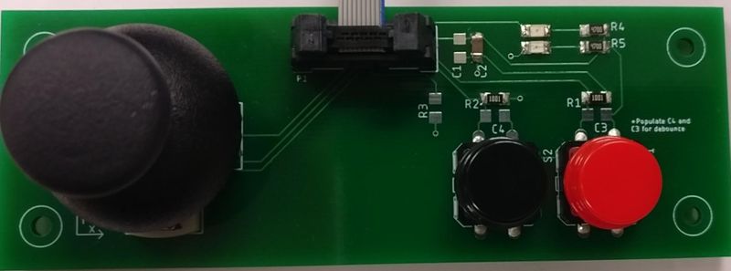
The gamepad controller consists of a joystick and two buttons.
- Joystick - move the cursor and decide where to place the towers.
- Black button - select and confirm the location of the towers.
- Red button - restart the game (If the player knows that he/she has made a mistake in the middle of the game and will eventually lose the game, the player can press the red button and restart the game.)
During the Intermission Phase:
- The player places towers strategically around the enemy path by using the joystick to move the cursor and pressing the black button to select the location of the towers.
- The player needs to place all remaining towers under 45 seconds.
During the Combat Phase:
- Cheer on your towers and watch them defend Earth from the alien invasion!
Hardware Design - Electrical
Overview
At a high level hardware integration requirements fell into two categories:
1. Reduce risk of unreliable cable connections and eliminate possibility of damage to components through unexpected disconnections, power surges, etc.
2. Provide a more fluid physical interface for the user to interact with the game via hardware
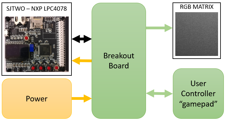
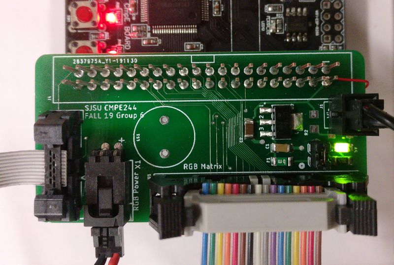
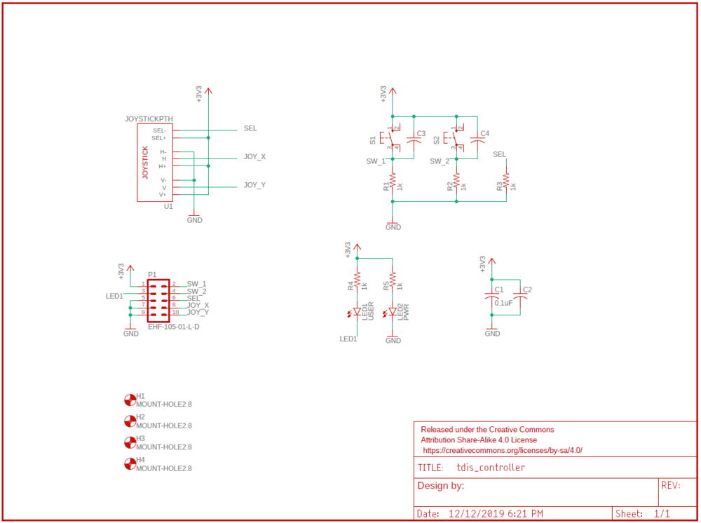
To accomplish these goals, two boards were designed: a breakout board and a gamepad controller. The breakout board serves as a connection hub between all system hardware components; power, the RGB matrix, the SJTWO board, etc. while the joystick provides a cleaner package to present the user with the games inputs. The diagram below shows the relationship between the main subsystems:
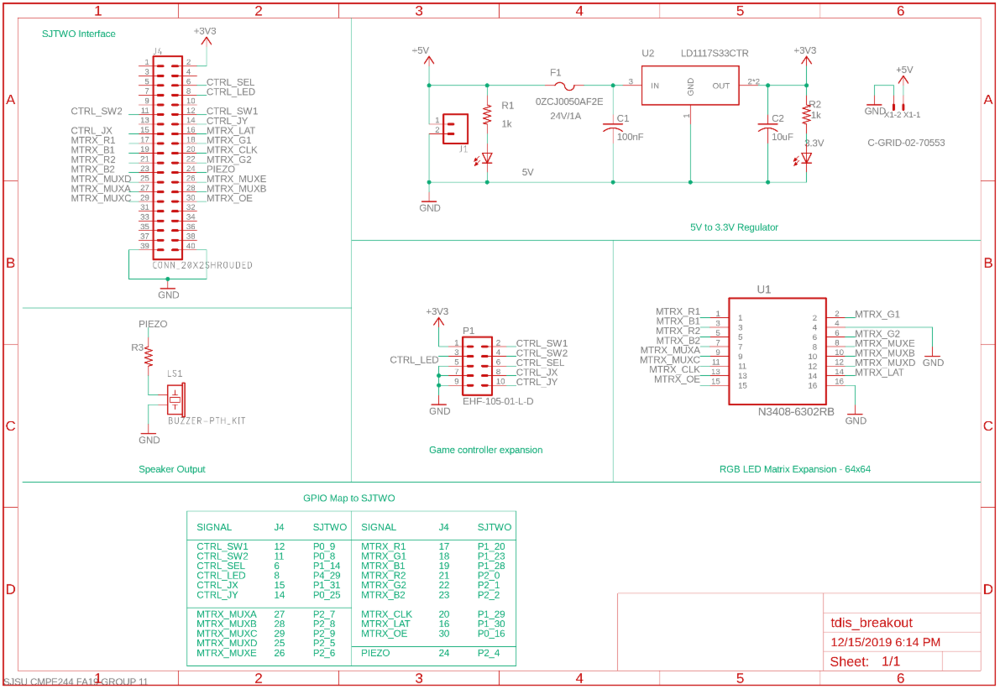
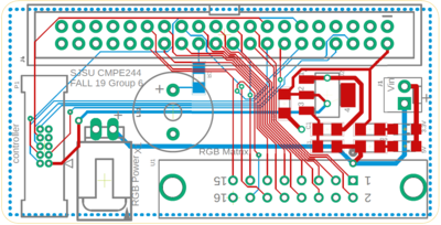
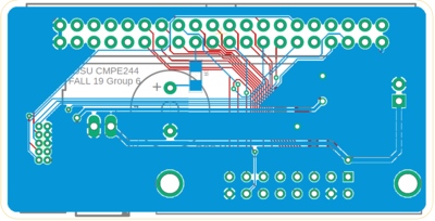
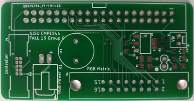
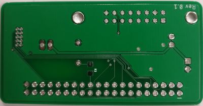
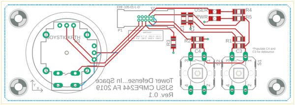
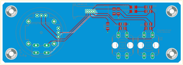
All board designs were done using EAGLE and manufactured by JLCPCB. Both boards were only two layers and used passive components for the most part.
Breakout Board Design
The breakout board design requirement was to interface all external hardware components with the embedded system (SJTWO). The hardware connections are:
1. The 64x64 RGB Matrix
2. Output power to the RGB Matrix
3. User game controller (see next section)
4. Input power supply (5V)
5. The SJTWO embedded system
Known Breakout PCB Issues
|
Known Issues | ||||
|---|---|---|---|---|
|
Summary |
Description |
Version |
Status | |
| 5V should not be routed to game controller. | 3.3V should be routed to the game controller instead of 5V since the ADC pins are not 5V tolerant. | 0.1 | Resolved Rev 0.2 | |
| Wrong silkscreen/not enough room near power input. | Power input silkscreen too small, part too big for 3.3V LED to fit | 0.1 | Resolved Rev 0.2 | |
| Linear regulator not needed. | The schematic for the SJTWO board labels the input voltage pin as VIN RAW, which is different than the label on the
optional input port. They are both the same, so this input feeds directly into the on-board 3.3V regulator. Essentially we're driving the regulator with the same voltage it outputs which just won't work well. |
0.1, 0.2 | UNRESOLVED | |
Gamepad Hardware Design
The gamepad board design requirement was to provide a more packaged interface for the user to interact with the game.
Hardware Design (Mechanical)
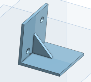
Only a few mechanical components were needed for this project. Namely simple brackets for mounting electrical hardware to the RGB matrix and displaying the matrix itself. All CAD designs were done using Onshape, a free CAD tool that can be used entirely through your web browser.
For displaying the RGB matrix, two brackets were 3D printed to prop it up. Their STL files can be found under our source repository.
Hardware Integration
RGB LED MATRIX
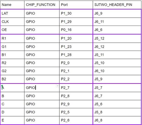
The LED matrix that we use is 64 pixels by 64 pixels and is controlled through a 12-pin header consisting of the following pins:
- Five Mux pins (A,B,C,D,E) for Row Selection
- In order to select a specific row of the LED matrix, we need to control the output level of each mux pin. Since the LED matrix light up two rows of LEDs at one time, we can only select 1 out of 32 rows.
- Two sets of RGB pins (R1,G1,B1,R2,G2,B2) for Color Selection
- Since we are driving two rows of LED matrix at once, we need 2 sets of RGB pins. One set is used to control the color pixels of the upper half of the display and the other set for the bottom half of the display.
- Output Enable Pin (OE)
- Output Enable (OE) pin is used to turn on or off the LEDs of the current row.
- Latch Pin (LAT)
- Latch pin is used to prevent the data being shifted into the shift registers and tells the shift register when it is time to switch to newly entered data.
- Clock Pin (CLK)
- triggers a shift on the shift registers
All these pins are required to display a specific color on a specific pixel of the LED matrix display.
Apparently, it is impossible to driver all 4096 LEDs all at one time and thus, we can only drive two rows of LEDs at a time (one row on the upper half of the display and another row on the lower half of the display). By refreshing the LED matrix two rows at a time in a fast frequency, we can display all the game objects with animation on the LED matrix.
Joysticker controller
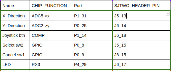
The joystick that we use is the product from Adafruit, the Analog 2-axis Thumb Joystick. This 2-axis Thumb Joystick provides the following pins:
- Two ADC pins
- In order to control the tower location, we need to control the Joysticker, since the direction has four: Up, Down, Left, Right, we use the Y and X-axis to implement this function.
- Three GPIO pins
- In order for selecting for the tool we need two GPIO pin for button and 1 GPIO pin for controlling the LED on the JOY STICKER controller
- Pin configuration
MP3 Decoder
The MP3 decoder that we use is Sparkfun’s vs1053 shield MP3 decoder which is the board based on the vs1053b chip.
- Three SPI pin
In order to communicate with the mp3 decoder with SJtwo Board, we choose the SPI as the protocol to control the decoder. Hence, we need the one pin SCK0 (clock), one pin MOSI(Master In Slave Out) and one pin (Master Out Slave In).
- Four GPIO pin for the decoder
There are four major GPIO pin for DREQ(Data Request Pin), Reset, CS(Chip Select), XDCS(Data Chip Select), this 4 GPIO pin is how we transfer data and send the command to activate the mp3 decoder work with SJ2 Board.
Software Design
RGB LED Matrix
All the LED Matrix data are stored in a buffer with its size equal to 32 by 64. Each element in this buffer store the color of two pixels, one pixel from the upper half of the display and one pixel from the lower half of the display.
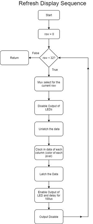
In order to display the gaming objects in animation, we need to refresh the display by displaying the color pixels on each row one by one very fast. Below is a simple flowchart that describes the process of refreshing the display.
- Loop through each row of the LED display
- Select Row (By controlling the output level of 5 mux pins, we can select one row at a time)
- Disable the LED Display output (Turn off the LEDs of the current row of the display)
- Unlatch the Data
- Clock in Data for each column(Store the color of each pixel inside display_matrix buffer)
- Latch the Data
- Enable the LED Display output (Display the color of each pixel of the current row)
- Delay for a 100us (Increase the light intensity of the LEDs by delay a short amount of time)
- Disable the LED Display output (Turn off the LEDs of the current row of the display)
void refreshDisplay(void) {
  for (uint8_t row = 0; row < LEDMATRIX_HALF_HEIGHT; row++) {

    select_row(row);
    led_matrix__disable_output(); // gpio__set(OE);
    led_matrix__unlatch_data();   // gpio__set(LAT);
    led_matrix__clock_in_data(row);
    led_matrix__latch_data();    // gpio__reset(LAT);
    led_matrix__enable_output(); // gpio__reset(OE);
    delay__us(100);              // Change Brightness
    led_matrix__disable_output();
  }
}
void led_matrix__clock_in_data(uint8_t row) {
/* Clock in data for each column */
for (uint8_t col = 0; col < LEDMATRIX_WIDTH; col++) {
/* Set all the RGB pins as low*/
LPC_GPIO1->PIN &= ~(0x1 << R1.pin_number | 0x1 << G1.pin_number | 0x1 << B1.pin_number);
LPC_GPIO2->PIN &= ~(0x1 << R2.pin_number | 0x1 << G2.pin_number | 0x1 << B2.pin_number);
/* Set the RGB pins as High or Low depends on the data stored inside the buffer */
LPC_GPIO1->PIN |= ((((display_matrix[row][col] >> 0) & 0x1) << R1.pin_number) |
(((display_matrix[row][col] >> 1) & 0x1) << G1.pin_number) |
(((display_matrix[row][col] >> 2) & 0x1) << B1.pin_number));
LPC_GPIO2->PIN |= ((((display_matrix[row][col] >> 4) & 0x1) << R2.pin_number) |
(((display_matrix[row][col] >> 5) & 0x1) << G2.pin_number) |
(((display_matrix[row][col] >> 6) & 0x1) << B2.pin_number));
gpio__set(CLK);
gpio__reset(CLK);
}
}
|
MP3 Decoder
The MP3 deocder is executed with the mainly two task: read task and play task. The reader task would read data from the sd card and sned queue data for the player task to play music.
- Read Task
- Loop through each row of the LED display
- Queue sned the target filename
- Queue receive the target name
- Find the mp3 file name is exit or not
- Open the file(fopen)
- Read data store to the buffer(Binary)
- Sent the data from bufder with queuesend API

|
- Play Task
Receive the data of the song from the queue, and use the receiving data and sent the command to make decoder to play music.
- Read Task
- Loop through each row of the LED display
- Queue receive the data(music)
- disable the chip select
- Check the DREQ pin to know is ready or not
- exchange the data to the decoder to play the music
- Check the DREQ pin to know is ready or not
- disable the chip select

|
JOY STICKER
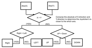
The JOY_STICKER is using the task to pool the ADC channel data to get the direction from the Joysticker.
- Loop through each time to poll the enum type data to get direction
- Receiving the data from two ADC channel(5=x, 4=y)
- Comparing which one has higher absolute data
- If (X > Y == YES) ,then we go to the loop to compare It's closer to Right or Left
- If (X > Y == YES && Right > LEFT == YES), then the status is Right
- If (X > Y == YES && Right > LEFT == NO), then the status is Left
- If (X > Y == NO) ,then we go to the loop to compare It's closer to Up or Down
- If (X > Y == NO && Up > Down == YES), then the status is Up
- If (X > Y == NO && Up > Down == NO), then the status is Down
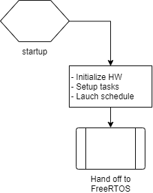
System Flow Charts
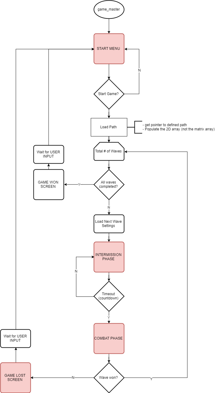
Game Master (how the user sees the game flowing):
Intermission Phase (what happens while the user is placing towers):
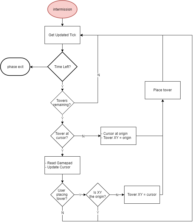
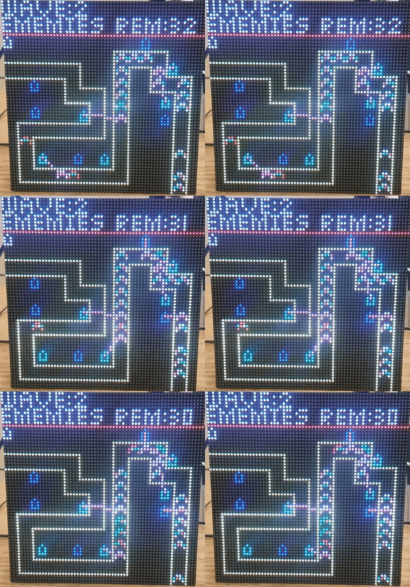
Combat Phase (what happens when the aliens invade):
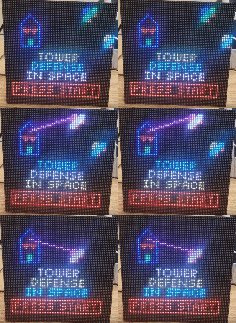
System Testing and Validation
Technical Challenges
Game Map (2D array) to LED matrix (2D pixels) Conversion
Issue:
- The game map (consisting of the path as well as all of the active enemies and towers) is managed through the use of a 2D char array.
- In order to display each object on the LED matrix, there needs to be a mechanism that converts the object along with its 2D array location to a row/column on the LED matrix.
- An algorithm to do this conversion is not as straightforward as it may appear. This is because objects stored in the array take up more/less display space than what is available on the LED matrix.
Solution:
- In order to align the array locations with the LED matrix pixel locations, some areas on the 2D array needed to be marked as "ignore".
- If each array location is not carefully correlated to a specific pixel location, then there would be issues where objects are displayed overlapping each other on the LED matrix (or simply displayed in the wrong spot).
- There were some simple algorithms that used math to help implement this conversion.
- However, a LUT is what was primarily used. It was not efficient in terms of code size, it took over 500 lines of code.
- But it was an effective solution and allowed us to easily decide exactly where each pixel of each object would be displayed.
LED Matrix Flickering Issue
Issue: While we are developing the game, we notice that some color pixels are turned on when they are supposed to be off.
Investigation/Solution:
- See Known Breakout PCB Issues as a possible cause. It's possible the SJTWO board is getting inconsistent power.
- Refreshing the matrix should not be handled by an interrupt and not a task. The task should only push new display data and not have direct control of the matrix. Keeping the refresh interrupt driven would keep the refresh rate more consistent by removing the process being context switched out mid update.
MP3 Decoder - SJtwo Board SPI Selection
Issue:
- The mp3 decoder1053b's document is a kind of confusing for the mode when 1032b have several modes
- It's hard to know the configuration is successful or not.
Solution:
- Doing the survey on the GitHub is really important. For example, using the sin wave and hello binary example to test how the Initialization and HZ parameter would save a lot of time.Moreover, in the document from the vs1053b, we could use the binary file line "hello", "sine wave" function for testing.
- Besides, we also have to be careful to check the SJBoard's SPI because of the SD card reader is using for reading SDcard. Hence, I would recommend using other
SPI0, SPI1 instead of using SPI2.
Conclusion
We successfully designed and implemented the video game "Tower Defense In Space". All of our team members now have a better understanding of how to use FreeRTOS to handle the synchronization of multiple tasks and to communicate with multiple hardware components in an embedded application system. After completing this project, we learned how to manage a project on a tight schedule. Starting from purchasing hardware components, developing hardware drivers and game logic and then integrating all of the drivers and APIs into the game logic. Furthermore, all of us are now better at coding and debugging code. For a game design project like this, we learned that it's not always best to assign tasks independently between the team members. We learned that this type of project would benefit moreso from pair programming and other cooperative tasks that enable collaboration between teammates. Otherwise, project tasks may be done in such a way that they only work for 1 specific configuration, and wouldn't help progress towards the end goal of the integrated system. We also learned that not every day was going to be perfect, but as long as we never gave up and worked hard, then the final result would not be disappointing!
We would like to say thank you to Prof. Preet and all the ISAs for their precious suggestions and assistance during the development of this project!
Advice for Future Students
Source Control
Unless everyone in your group is comfortable using source control, don't use it. It will likely end up costing you time in the long run.
Start working on your LED Matrix driver ASAP
The first 64x64 LED Matrix that we got from Sparkfun suffers from a serious flickering issue. After spending for a week trying to debug what causes the flickering issue, we still have no idea whether it is a hardware issue or software issue. Later, we borrow another LED matrix from a student of our class and test our code. With the other student's LED matrix (we use our own power supply and ribbon cables), there is no flickering issue at all. According to some online resources, some matrix vendors scatter the selected rows and columns differently. It is possible that your designed driver may only work on some LED matrix vendors' displays.
