Difference between revisions of "F20: Bubble Shooter"
Proj user7 (talk | contribs) |
Proj user7 (talk | contribs) (→Bill Of Materials) |
||
| (197 intermediate revisions by the same user not shown) | |||
| Line 3: | Line 3: | ||
Bubble shooter is an arcade game that has bubbles or balls present on the screen. The bubbles are of different colors and the goal is to clear them by forming a group of bubbles (3 or more) of the same color. Points are earned upon clearing the bubbles and increases with the number of bubbles cleared in a single shot. The player wins upon clearing the screen and loses when the bubbles touch the bottom of the screen. | Bubble shooter is an arcade game that has bubbles or balls present on the screen. The bubbles are of different colors and the goal is to clear them by forming a group of bubbles (3 or more) of the same color. Points are earned upon clearing the bubbles and increases with the number of bubbles cleared in a single shot. The player wins upon clearing the screen and loses when the bubbles touch the bottom of the screen. | ||
| − | =='''Objectives & Introduction'''== | + | |
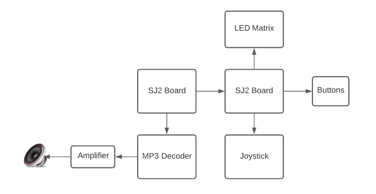
| − | + | [[File:Abstract_Bubble_Shooter.png|800px|thumb|center|Block Diagram of Bubble Shooter]] | |
| + | |||
| + | == '''Objectives & Introduction''' == | ||
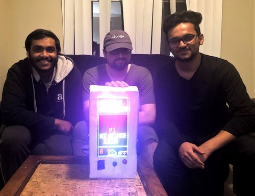
| + | [[File:Project Pic.jpg|thumb|500x500px|Team Bubble Shooter|right]] | ||
| + | |||
| + | The objective of this project is to develop a single-player 2D arcade game using LPC 4078 microcontroller on a 64 X 32 LED matrix display. The project focuses on integrating SJ2 microcontroller board with LED Matrix, MP3 Decoder, 2 pushbuttons, and joystick. | ||
| + | The micro-controller is integrated with peripheral drivers, led drivers, MP3 player, button, and joystick controller interface. The application software in FreeRTOS. The button controller interface consists of the joystick for moving the shooter left and right. A button is used to fire the ball. | ||
=== Team Members === | === Team Members === | ||
| Line 12: | Line 18: | ||
* '''''[https://www.linkedin.com/in/hisaam-hashim/ Hisaam Hashim]''''' | * '''''[https://www.linkedin.com/in/hisaam-hashim/ Hisaam Hashim]''''' | ||
| − | == | + | == '''Technical Responsibilities''' == |
| − | |||
{| class="wikitable" style="margin-left: 0px; margin-right: auto;" | {| class="wikitable" style="margin-left: 0px; margin-right: auto;" | ||
|- style="vertical-align: top;" | |- style="vertical-align: top;" | ||
| Line 26: | Line 31: | ||
|- | |- | ||
! style="text-align: left;" | | ! style="text-align: left;" | | ||
| − | * LED Display Driver | + | * LED and Graphics Display Driver |
| Hisaam Hashim | | Hisaam Hashim | ||
|- | |- | ||
| − | |||
| − | |||
| − | |||
|- | |- | ||
! style="text-align: left;" | | ! style="text-align: left;" | | ||
* Mp3 Decoder Driver | * Mp3 Decoder Driver | ||
| − | | Amiraj Nigam | + | | Amiraj Nigam |
|- | |- | ||
! style="text-align: left;" | | ! style="text-align: left;" | | ||
| Line 43: | Line 45: | ||
! style="text-align: left;" | | ! style="text-align: left;" | | ||
* Hardware Integration | * Hardware Integration | ||
| − | | Amiraj Nigam, Hisaam Hashim | + | | Amiraj Nigam, Anirudh Ashrit, Hisaam Hashim |
|- | |- | ||
|} | |} | ||
| − | == | + | == '''Administrative Responsibilities''' == |
{| class="wikitable" style="margin-left: 0px; margin-right: auto;" | {| class="wikitable" style="margin-left: 0px; margin-right: auto;" | ||
| Line 58: | Line 60: | ||
! style="text-align: left;" | | ! style="text-align: left;" | | ||
* Git Repository Managers | * Git Repository Managers | ||
| − | | Akshat Bhutiani | + | | Akshat Bhutiani |
|- | |- | ||
! style="text-align: left;" | | ! style="text-align: left;" | | ||
| Line 70: | Line 72: | ||
! style="text-align: left;" | | ! style="text-align: left;" | | ||
* Bill of Materials Manager | * Bill of Materials Manager | ||
| − | | | + | | Amiraj Nigam |
|- | |- | ||
|} | |} | ||
| − | |||
== '''Schedule''' == | == '''Schedule''' == | ||
| Line 234: | Line 235: | ||
*Update the wiki page. | *Update the wiki page. | ||
| | | | ||
| − | * <span style="color: | + | * <span style="color:green">Completed</span> |
| − | * <span style="color: | + | * <span style="color:green">Completed</span> |
| − | * <span style="color: | + | * <span style="color:green">Completed</span> |
| − | * <span style="color: | + | * <span style="color:green">Completed</span> |
|- | |- | ||
|} | |} | ||
| − | |||
| − | |||
<BR/> | <BR/> | ||
| − | + | == '''Bill Of Materials''' == | |
| − | =='''Bill Of Materials'''== | ||
{| class="wikitable" style="margin-left: 0px; margin-right: auto;" | {| class="wikitable" style="margin-left: 0px; margin-right: auto;" | ||
|- | |- | ||
| Line 256: | Line 254: | ||
| Microcontroller Boards | | Microcontroller Boards | ||
| SJ2 Boards (Purchased from Preet Kang) | | SJ2 Boards (Purchased from Preet Kang) | ||
| − | | | + | | 2 |
| − | | $ | + | | $100.00 |
|- | |- | ||
! scope="row"| 2 | ! scope="row"| 2 | ||
| Line 282: | Line 280: | ||
| 1 | | 1 | ||
| $8.99 | | $8.99 | ||
| + | |- | ||
| + | ! scope="row"| 6 | ||
| + | | PAM8403 Amplifier and Speaker | ||
| + | | [https://www.amazon.com/gp/product/B07CRVRG83/ref=ppx_yo_dt_b_asin_title_o00_s00?ie=UTF8&psc=1 Amplifier and Speaker] | ||
| + | | 1 | ||
| + | | $11.99 | ||
| + | |- | ||
| + | ! scope="row"| 7 | ||
| + | | Push Buttons | ||
| + | | [https://www.amazon.com/gp/product/B07SVSYDNM/ref=ppx_yo_dt_b_asin_title_o09_s00?ie=UTF8&psc=1 Push Buttons] | ||
| + | | 1 | ||
| + | | $7.99 | ||
|} | |} | ||
<BR/> | <BR/> | ||
| − | =='''PCB Design'''== | + | == '''PCB Design''' == |
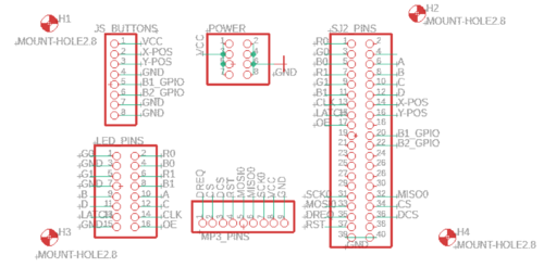
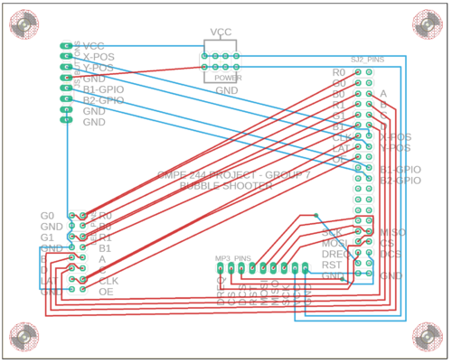
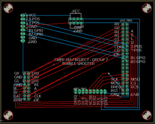
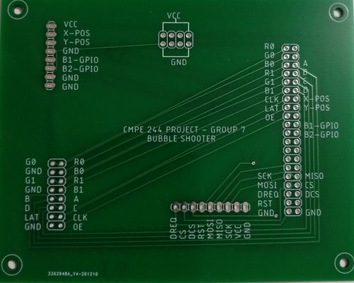
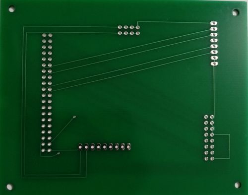
| − | The board is designed to connect modules in the game directly. Autodesk's Eagle software is used to design the Schematics and Board layout. The board has 2 layers(Top and Bottom). JLCPCB is the manufacturer of the PCB board. | + | The board is designed to connect modules in the game directly. Autodesk's Eagle software is used to design the Schematics and Board layout. The board has 2 layers(Top and Bottom). JLCPCB is the manufacturer of the PCB board. Connections from SJ2 Board are provided to the PCB, which are internally connected to MP3 Decoder, Joystick, Buttons, and LED Matrix pins. These are connected directly to the peripherals using a harness. Additional power and ground pins are also provided on the board. |
| − | |||
| − | |||
| − | |||
| + | [[File:PCB_Schematic_BS.png|500x600px|thumb|left|Schematic Design of PCB]] | ||
| + | {| | ||
| + | |[[File:PCB_Board_Overview.png|500x600px|thumb|center|Design Overview of the PCB]] | ||
| + | |[[File:PCB_front.png|500x600px|thumb|right|PCB Board Layout]] | ||
| + | |} | ||
{| | {| | ||
| − | [[File: | + | |[[File:PCB_Bubble_Shooter_Front.jpg|500x600px|thumb|left|PCB Front Face]] |
| − | |[[File: | + | |[[File:PCB_Bubble_Shooter_Back.jpg|500x600px|thumb|center|PCB Back Face]] |
|} | |} | ||
| + | == '''Joystick'''== | ||
| − | == | + | === Hardware Design === |
| − | |||
| − | |||
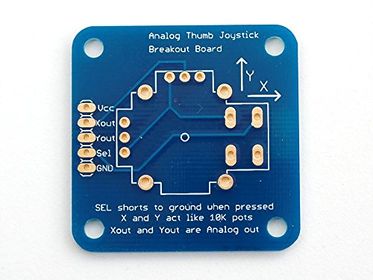
An ADA512 2-axis Analog Joystick and Button is used for controlling the movement of the launcher and shooting the ball. The data from the joystick is read using the ADC pins of the SJTwo board. The button switch is detected using a digital pin on the board. | An ADA512 2-axis Analog Joystick and Button is used for controlling the movement of the launcher and shooting the ball. The data from the joystick is read using the ADC pins of the SJTwo board. The button switch is detected using a digital pin on the board. | ||
| − | + | Features of the joystick: | |
| − | |||
| − | |||
| − | |||
| − | |||
| − | |||
| − | |||
| − | |||
| − | |||
| − | |||
| − | |||
| − | |||
| − | |||
| − | |||
| − | |||
| − | |||
| − | |||
| − | |||
| − | |||
| − | |||
| + | 1. Usable with any voltage up to 5V | ||
| + | 2. Analog outputs | ||
| + | 3. 1 mA draw when used with 5V | ||
| + | 4. On-board button | ||
| + | 5. High sensitivity | ||
| + | {| | ||
| + | [[File:Break out board.jpg|500x280px |thumb|left|Breakout board layout]] | ||
| + | |[[File:.Soldered and working.jpg|500x280px |thumb|center|Soldered joystick]] | ||
| + | |} | ||
| + | ===Software Design & Implementation=== | ||
| + | The ADA512 joystick's device driver works on the principle that the ADC pins will be able to read the x and y values. The joystick consists of 2 inbuilt potentiometers that provide output (x and y directions) according to the way the joystick is moved. | ||
{| class="wikitable" | {| class="wikitable" | ||
| Line 350: | Line 353: | ||
|} | |} | ||
| + | <font color="black"> '''Steps to read joystick data:''' </font> | ||
| + | |||
| + | 1. Turn on the ADC Peripheral | ||
| + | |||
| + | 2. Make the ADC pin operational by setting the appropriate pin functionality using the IOCON registers. | ||
| + | |||
| + | 3. Set the appropriate ADC clock (12.4 MHz is the maximum clock supported by the ADC). | ||
| + | |||
| + | 4. Set the ADC pin functionality as input. | ||
| + | |||
| + | 5. Select the number of channels to read. | ||
| + | 6. Select burst mode for immediate conversion. | ||
| + | void adc__initialize_alien(void) | ||
| + | { | ||
| + | Turn ON ADC peripheral; | ||
| + | make ADC operational; | ||
| + | set ADC clock; | ||
| + | Set Pin functions; | ||
| + | select ADC channels; | ||
| + | start burst mode; | ||
| + | } | ||
| + | data get_data(adc_channel_e x_port, adc_channel_e y_port, gpio_s button_press) { | ||
| + | data s; | ||
| + | s.x_data = adc__get_adc_value(x_port); | ||
| + | s.y_data = adc__get_adc_value(y_port); | ||
| + | if (gpio__get(button_press)) { | ||
| + | s.switch_pressed = true; | ||
| + | } else { | ||
| + | s.switch_pressed = false; | ||
| + | } | ||
| + | return s; | ||
| + | } | ||
| + | == '''MP3 Decoder''' == | ||
| − | + | The MP3 shield communicates with the sister SJ2 board through SPI communication protocol with the SPI0 pins of the SJ2 board as follows: | |
| − | |||
{| class="wikitable" | {| class="wikitable" | ||
|- | |- | ||
| Line 363: | Line 398: | ||
! scope="col"| Function | ! scope="col"| Function | ||
! scope="col"| Pin Connection | ! scope="col"| Pin Connection | ||
| + | ! scope="col"| Description | ||
|- | |- | ||
! scope="row"| 1 | ! scope="row"| 1 | ||
| Line 368: | Line 404: | ||
| Decoder Data Request | | Decoder Data Request | ||
| Pin 0.1 | | Pin 0.1 | ||
| + | | MP3 decoder signals to master to ready to receive next 32 bytes of data | ||
|- | |- | ||
! scope="row"| 2 | ! scope="row"| 2 | ||
| Line 373: | Line 410: | ||
| VS1053B Chip Select | | VS1053B Chip Select | ||
| Pin 0.22 | | Pin 0.22 | ||
| + | | Chip select pin for MP3 decoder to be activated while sending control signals | ||
|- | |- | ||
! scope="row"| 3 | ! scope="row"| 3 | ||
| Line 378: | Line 416: | ||
| VS1053B Data CS | | VS1053B Data CS | ||
| Pin 0.0 | | Pin 0.0 | ||
| + | | Data Chip Select Pin for the MP3 decoder to be activated while sending audio data signals. | ||
|- | |- | ||
! scope="row"| 4 | ! scope="row"| 4 | ||
| Line 383: | Line 422: | ||
| VS1053 Reset | | VS1053 Reset | ||
| Pin 0.10 | | Pin 0.10 | ||
| + | | Reset pin for the MP3 Decoder | ||
|- | |- | ||
! scope="row"| 5 | ! scope="row"| 5 | ||
| MOSI | | MOSI | ||
| − | | | + | | Master Output Slave Input |
| Pin 0.18 | | Pin 0.18 | ||
| + | | Master send data to Slave over SPI bus | ||
|- | |- | ||
! scope="row"| 6 | ! scope="row"| 6 | ||
| Line 393: | Line 434: | ||
| SPI Bus (Master Input Slave Output) | | SPI Bus (Master Input Slave Output) | ||
| Pin 0.17 | | Pin 0.17 | ||
| + | | Slave send data to master over SPI bus | ||
|- | |- | ||
! scope="row"| 7 | ! scope="row"| 7 | ||
| Line 398: | Line 440: | ||
| SPI Clock | | SPI Clock | ||
| Pin 0.15 | | Pin 0.15 | ||
| + | | Clock generated by the master over SPI bus | ||
|- | |- | ||
! scope="row"| 8 | ! scope="row"| 8 | ||
| Line 403: | Line 446: | ||
| +5V | | +5V | ||
| PCB Vout | | PCB Vout | ||
| + | | 5 Volt Input from PCB | ||
|- | |- | ||
! scope="row"| 9 | ! scope="row"| 9 | ||
| Line 408: | Line 452: | ||
| GND | | GND | ||
| GND | | GND | ||
| + | | GND connected to PCB | ||
|} | |} | ||
| + | ===Hardware Design=== | ||
| + | |||
| + | [[File:MP3 Layout.png|800x1200px|thumb|center|MP3 Layout]] | ||
| + | |||
| + | ===Software Design=== | ||
| + | |||
| + | [[File:MP3 Flow Chart(1).png|700x800px|thumb|center|MP3 Layout]] | ||
| + | |||
| + | ===Implementation=== | ||
| + | To initialize the MP3 decoder, we have first initialized the SSP0 and the SJ2 pins connected to the MP3 decoder with proper input/output function configurations. We then configure the decoder registers by selecting the MP3 chip select pin and writing data over SPI. These include the mode (default), clock frequency multiplier (3x), volume (max), and audio (44100 Hz stereo data). We then flush the mp3 decoder, sending it 2500 0 bytes. | ||
| + | Reading the MP3 File from an SD Card[edit] | ||
| + | We create a low priority task (read_song_from_sd_card) to read from the SD Card. Read_song_from_sd_card task first opens the mp3 file on the sd card and determines the size. Afterward, it reads in 512 bytes at a time to a global array (whenever the music playing task has finished playing the previous 16 bytes) and sets a global variable (sdready) to true. It will continue to do this until the file has been completely read, and then start over from the beginning. | ||
| + | |||
| + | ===Feeding the Decoder and Playing Music=== | ||
| + | We create another low priority task (play_song_task) to play music. If the MP3 DREQ pin is currently set, it delays. Otherwise, whenever sdready is true, it selects the Data chip select line and sends 32 bytes over the SPI bus. It then deselects data chip select and redoes this 16 times (sending the 512 bytes that have been read). After it has sent all 512 bytes, it sets sdready to false so the read_song_from_sd_card task knows to read in the next 512 bytes. It continues to repeat this process for as long as mp3sdcard reads in data to the array. | ||
| + | |||
| + | Task to read song from sd card | ||
| + | void read_level_1_bgm_from_sdcard(void *p) { | ||
| + | vTaskSuspend(NULL); | ||
| + | unsigned int ptr_to_bytes_read = 0; | ||
| + | while (1) { | ||
| + | const char filename_path[] = "level1.mp3"; | ||
| + | FIL song; | ||
| + | // Open or creates a file | ||
| + | FRESULT check = f_open(&song, filename_path, (FA_READ | FA_OPEN_ALWAYS)); | ||
| + | if (FR_OK == check) { | ||
| + | f_lseek(&song, f_size(&song)); | ||
| + | current_position_in_mp3_file = f_tell(&song); | ||
| + | current_position_in_mp3_file /= 32; | ||
| + | f_lseek(&song, 0); | ||
| + | mp3_file_size = 0; | ||
| + | song_position = 0; | ||
| + | f_read(&song, &data_buffer, BYTES_TO_READ, &ptr_to_bytes_read); | ||
| + | while (mp3_file_size < current_position_in_mp3_file + 32) { | ||
| + | if (song_position == 16 & sdready == false || sdready == false) { | ||
| + | f_read(&song, &data_buffer, BYTES_TO_READ, &ptr_to_bytes_read); | ||
| + | mp3_file_size += 16; | ||
| + | song_position = 0; | ||
| + | sdready = true; | ||
| + | } | ||
| + | vTaskDelay(1); | ||
| + | } | ||
| + | printf("Song finished! \n"); | ||
| + | f_close(&song); | ||
| + | song_position = 0; | ||
| + | mp3_file_size = 0; | ||
| + | vTaskDelay(500); | ||
| + | } | ||
| + | else { | ||
| + | printf("Failed to read SD card \n"); | ||
| + | } | ||
| + | vTaskDelay(1); | ||
| + | } | ||
| + | } | ||
| + | |||
| + | |||
| + | Task to play song | ||
| + | void play_song_task(void *p) { | ||
| + | vTaskSuspend(NULL); | ||
| + | while (mp3_file_size < current_position_in_mp3_file + 32) { | ||
| + | while ((song_position < 16) && (sdready == true) && (mp3_sel == 0)) { | ||
| + | while (!(LPC_GPIO0->PIN & (MP3_DREQ))) { | ||
| + | vTaskDelay(1); | ||
| + | ; | ||
| + | } | ||
| + | LPC_GPIO0->CLR = (MP3_DCS); | ||
| + | for (int a = 0; a < 32; a++) { | ||
| + | spi0_ExchangeByte(data_buffer[a + (song_position * 32)]); | ||
| + | } | ||
| + | // sdready = false; | ||
| + | song_position++; | ||
| + | LPC_GPIO0->SET = (MP3_DCS); | ||
| + | if (song_position == 16) { | ||
| + | mp3_sel = 0; | ||
| + | sdready = false; | ||
| + | } | ||
| + | } | ||
| + | } | ||
| + | } | ||
| + | ===Binary Semaphore=== | ||
| + | We have low priority created check_which_song_recieved_from_main_sj2_board_semaphore_give which will act as a producer task which will select which mp3 background music or sound fx need to be played and it will give the semaphore of the selected music file to the high priority consumer task called play_song_task which will suspend all other song handlers and play the selected song. | ||
| + | ===Communication between Main and Sister SJ2 board=== | ||
| + | We have initialized 3 GPIO pins on the main(P0.15, P0.18, P0.1) and sister board(P2.0, P2.2, P2.5) and we have a total of 8 songs list, to which the respective GPIO pins will be high or low based on the song selection. The GPIO pins on the mainboard will be the output pins and the GPIO pins on the sister board will be the input pins. Henceforth, the sister board will receive input from the mainboard for the song selection and a binary semaphore will play the song. | ||
| + | == '''LED Matrix''' == | ||
| + | === Hardware Design === | ||
| + | We use a 32x64 LED matrix consisting of 2048 LEDs arranged in 32 rows and 64 columns each, with each led having separate Red, Green, and Blue LED chips assembled together as a single unit. This 32x64 LED matrix is comprised of 2 of 16x32 led matrices placed vertically to each other. There are different drivers for controlling the corresponding rows and columns each. In order to illuminate a particular led, one needs to access and control the corresponding row and column (just like the coordinate-axis). To change the color of a particular led, each led must be controlled using the driver for that row and column. A layout of pins and connections can be seen below: | ||
| + | [[File:LED_Bubble_Shooter_Pin_Layout.png|800x300px |thumb|left|LED Matrix and SJ2 Connections]] | ||
| + | [[File:LED_Ribbon.png|800x300px |thumb|right|LED Matrix Ribbon Connector]] | ||
| + | {| class="wikitable" | ||
| + | |- | ||
| + | ! scope="col"| LED Matrix Pins | ||
| + | ! scope="col"| Connection to SJTwo board | ||
| + | |- | ||
| + | ! scope="col"| R0 | ||
| + | ! scope="col"| Pin 0.1 | ||
| + | |- | ||
| + | ! scope="col"| G0 | ||
| + | ! scope="col"| Pin 1.1 | ||
| + | |- | ||
| + | ! scope="col"| B0 | ||
| + | ! scope="col"| Pin 1.4 | ||
| + | |- | ||
| + | ! scope="col"| R1 | ||
| + | ! scope="col"| Pin 4.28 | ||
| + | |- | ||
| + | ! scope="col"| B1 | ||
| + | ! scope="col"| Pin 0.6 | ||
| + | |- | ||
| + | ! scope="col"| G1 | ||
| + | ! scope="col"| Pin 0.8 | ||
| + | |- | ||
| + | ! scope="col"| A | ||
| + | ! scope="col"| Pin 1.23 | ||
| + | |- | ||
| + | ! scope="col"| B | ||
| + | ! scope="col"| Pin 1.29 | ||
| + | |- | ||
| + | ! scope="col"| C | ||
| + | ! scope="col"| Pin 2.1 | ||
| + | |- | ||
| + | ! scope="col"| D | ||
| + | ! scope="col"| Pin 2.4 | ||
| + | |- | ||
| + | ! scope="col"| CLK | ||
| + | ! scope="col"| Pin 0.26 | ||
| + | |- | ||
| + | ! scope="col"| STB | ||
| + | ! scope="col"| Pin 1.31 | ||
| + | |- | ||
| + | ! scope="col"| OE | ||
| + | ! scope="col"| Pin 1.20 | ||
| + | |- | ||
| + | ! scope="col"| GND | ||
| + | ! scope="col"| GND | ||
| + | |- | ||
| + | |} | ||
| + | <BR/> | ||
| + | The matrix pixels are controlled by 6 drivers, 3 for the top half of the matrix(R0, G0, B0) and 3 for the bottom half(R1, G1, B1). The three drivers for R, G, and B share an SCLK, Latch, and OE signal. The top half pixels of the matrix controlled by R0, G0, B0 are rows 0-15, and the second half controlled by R1, G1, B1 are rows 16-31. The display is multiplexed at a duty cycle of 1/16, this means that one row in the top half and one row in the bottom half will be illuminated at a time. In order to display an image, the row and column LEDs for that image must be turned “ON”, therefore, the entire panel must be scanned at a rate(speed) at which it appears that the image is being displayed without flickering. To display different colors and different brightness levels, the LED chips of the corresponding row and column must be adjusted by varying the amount and time that each LED chip is turned on during each cycle. | ||
| + | ===LED Matrix Specifications=== | ||
| + | 5V regulated power input, 4A max (all LEDs on) | ||
| + | 2.1 mm x 2.1 mm LED size | ||
| + | 1/16 Scan Rate | ||
| + | {| | ||
| + | [[File:LED Matrix Schematic.png|800x300px |thumb|left|LED Matrix Interfacing]] | ||
| + | |[[File:LED Bubble Shooter.png|800x300px |thumb|center|Start Screen of the game]] | ||
| + | |} | ||
| − | |||
| − | |||
=== Software Design === | === Software Design === | ||
| − | |||
| − | === Implementation === | + | The game has 3 levels apart from the main menu, Credit scene, and Game-over screen. Just like any other arcade game, the game only starts when you earn credits and it is earned by pressing a button. The game begins with the press of another button. A block of bubbles starts falling down with every turn and finishes if it touches the danger line below. Bubbles, when hit with similar color, get destroyed and the game advances to the next level when all the bubbles on the screen are cleared. There's also a hack to traverse through levels, just press the credit score button and it will do the job for you. But hey, that's a cheat code, so you're a cheater! |
| − | + | ||
| + | '''RGB Color Combo''' | ||
| + | {| class="wikitable" | ||
| + | |- | ||
| + | ! scope="col"| Red | ||
| + | ! scope="col"| Blue | ||
| + | ! scope="col"| Green | ||
| + | ! scope="col"| Color | ||
| + | |- | ||
| + | ! scope="row"| 0 | ||
| + | | 0 | ||
| + | | 0 | ||
| + | | White | ||
| + | |- | ||
| + | ! scope="row"| 0 | ||
| + | | 0 | ||
| + | | 1 | ||
| + | | Blue | ||
| + | |- | ||
| + | ! scope="row"| 0 | ||
| + | | 1 | ||
| + | | 0 | ||
| + | | Green | ||
| + | |- | ||
| + | ! scope="row"| 0 | ||
| + | | 1 | ||
| + | | 1 | ||
| + | | Cyan | ||
| + | |- | ||
| + | ! scope="row"| 1 | ||
| + | | 0 | ||
| + | | 0 | ||
| + | | Red | ||
| + | |- | ||
| + | ! scope="row"| 1 | ||
| + | | 0 | ||
| + | | 1 | ||
| + | | Magenta | ||
| + | |- | ||
| + | ! scope="row"| 1 | ||
| + | | 1 | ||
| + | | 0 | ||
| + | | Yellow | ||
| + | |- | ||
| + | ! scope="row"| 1 | ||
| + | | 1 | ||
| + | | 1 | ||
| + | | Black | ||
| + | |} | ||
| + | |||
| + | <font color="black"> '''Implementation''' </font> | ||
| + | |||
| + | 1. Initialize the LED matrix by configuring necessary pin directions. | ||
| + | 2. Disable Output Enable (OE) GPIO before feeding matrix data. | ||
| + | 3. Select the required row by setting bits on A, B, C, D GPIO pins. | ||
| + | 4. Loop through the pixels (columns) in the selected row and set the pixel color on R, G, B GPIO pins. | ||
| + | 5. Set zero on R, G, B GPIO pins to mask that particular pixel. | ||
| + | 6. Set and Reset the clock for pushing the R, G, B bits for each column. | ||
| + | 7. Issue latch to mark the row's completion and reset the latch before going to the next row. | ||
| + | 8. Follow steps 2 to 7 for other rows. | ||
| + | |||
| + | for (uint8_t row = 0; row < (MAX_ROW); row++) { | ||
| + | disableOE(); | ||
| + | set_row(row); | ||
| + | for (uint8_t col = 0; col < MAX_COL; col++) { | ||
| + | LPC_GPIO0->PIN |= (1 << CLK); | ||
| + | set_color_bottom(game_matrix[row + (MAX_ROW / 2)][col]); | ||
| + | set_color_top(game_matrix[row][col]); | ||
| + | LPC_GPIO0->PIN &= ~(1 << CLK); | ||
| + | } | ||
| + | LPC_GPIO0->PIN |= (1 << LAT); | ||
| + | enableOE(); | ||
| + | LPC_GPIO0->PIN &= ~(1 << LAT); | ||
| + | enableOE(); | ||
| + | vTaskDelay(1); | ||
| + | } | ||
| + | |||
| + | === Graphics Driver === | ||
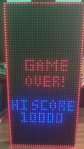
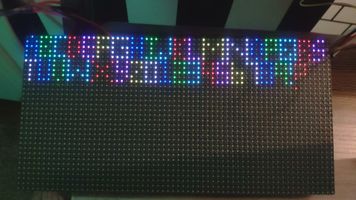
| + | We have managed to program the graphics in a relatively simple way by looking at the ADAFruit gfx library that comes ready to use with Arduino. Our graphics driver can implement graphics and animations such as letters, numbers, ball appearance and ball disappearance etc. | ||
| + | |||
| + | void place_launcher(LedMatrixDisplay led_display, pixel_color rgb, gfx__cursor start_cursor, bool | ||
| + | choose_back_frame) { | ||
| + | game_event object_property = BACKGROUND_OBJECT; | ||
| + | rgb.event = object_property; | ||
| + | draw_line(led_display, rgb, ROTATION_90, start_cursor, 9, choose_back_frame); | ||
| + | modify_pixel(led_display, rgb, start_cursor.x + 0, start_cursor.y + 1, choose_back_frame); | ||
| + | modify_pixel(led_display, rgb, start_cursor.x + 0, start_cursor.y + 2, choose_back_frame); | ||
| + | modify_pixel(led_display, rgb, start_cursor.x + 1, start_cursor.y + 3, choose_back_frame); | ||
| + | modify_pixel(led_display, rgb, start_cursor.x + 2, start_cursor.y + 4, choose_back_frame); | ||
| + | modify_pixel(led_display, rgb, start_cursor.x + 3, start_cursor.y + 5, choose_back_frame); | ||
| + | modify_pixel(led_display, rgb, start_cursor.x + 4, start_cursor.y + 5, choose_back_frame); | ||
| + | modify_pixel(led_display, rgb, start_cursor.x + 5, start_cursor.y + 5, choose_back_frame); | ||
| + | modify_pixel(led_display, rgb, start_cursor.x + 6, start_cursor.y + 4, choose_back_frame); | ||
| + | modify_pixel(led_display, rgb, start_cursor.x + 7, start_cursor.y + 3, choose_back_frame); | ||
| + | modify_pixel(led_display, rgb, start_cursor.x + 8, start_cursor.y + 1, choose_back_frame); | ||
| + | modify_pixel(led_display, rgb, start_cursor.x + 8, start_cursor.y + 2, choose_back_frame); | ||
| + | } | ||
| + | |||
| + | {| | ||
| + | [[File:level.jpg|500x300px |thumb|left|Game Level 1]] | ||
| + | |[[File:gameover.png|500x300px |thumb|right|Game Over Screen]] | ||
| + | |[[File:graphics.jpg|400x200px |thumb|center|Graphics display]] | ||
| + | |} | ||
| + | |||
| + | == '''Game Engine''' == | ||
| + | [[File:game logic.jpeg|1000x1000px|thumb|center|Game Design]] | ||
| + | |||
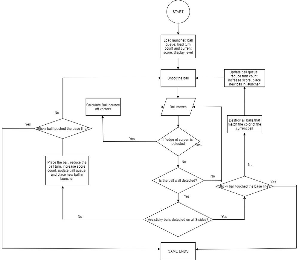
| + | The game starts with the Main Menu, which has the number of turns, score, and Level on the top. A credit count and Ball queue are placed at the bottom of the screen. Once the credit button is pressed and credits are accumulated and the game starts by pressing the trigger button. A bubble is ready inside the trigger and the player just needs to adjust the pointer and shoot in the desired direction. Two other bubbles based on the number of colored bubbles present on the top is available in the queue. After the ball is released from the trigger it checks the property of the above objects and functions accordingly. If the released bubble encounters a border wall, then it bounces off in the opposite direction, if it encounters the bubbles then sticks to it if it's a different color, else destroys all the same colored bubbles. And finally, if the ball touches the Wall on the top then it doesn't stick but gets destroyed. The trigger remains empty and the queue still has the old bubbles. Based on the final function of the released bubble, a function scans the number of different colored bubbles in the stack and calculates the color of bubbles that are present in more. The trigger and queue then get updated with new bubbles and the wall comes down a bit further near the danger line. | ||
| + | |||
| + | The above process keeps happening until either all the bubbles are cleared, the wall reaches the danger line, or you cheat your way to the next level. Have fun playing! | ||
| + | |||
| + | == '''Testing & Technical Challenges''' == | ||
| + | As with any other project, even this threw challenges along the way. | ||
| + | |||
| + | === LED Matrix === | ||
| + | 1. Understanding the matrix and then getting it to run was difficult as proper documentation or resource for the matrix was not available. | ||
| + | |||
| + | 2. OE pin was not active low and it took us some time to figure it out. | ||
| + | |||
| + | 3. Bubble, after released by the player, should move in the direction of the pointer and bounce off the border wall. | ||
| + | |||
| + | A graphics library was developed to print Alphanumerics in both horizontal and vertical positions. The driver was designed in a way to simply accept the coordinates of the board, shape, and color of the bubble instead of plotting it manually. | ||
| + | |||
| + | === MP3 Decoder === | ||
| + | 1. Communicating with the decoder using SSP was challenging and took multiple rounds of debugging to start playing the tracks. | ||
| + | |||
| + | 2. Switching between the songs when levels change also gave some issues. | ||
| + | |||
| + | Inputs from SJ2 were enabled to indicate the level change within the state machine, this way when the level changed the respective pin indicated the song to be played. | ||
| + | |||
| + | === Game Design === | ||
| + | 1. First major challenge was to clear all the same colored bubbles once it was hit by the player bubble. | ||
| + | |||
| + | 2. The Second challenge was to figure out an algorithm for the released bubble to either get attached or destroyed when it touches the bubble-block. | ||
| + | |||
| + | 3. Designing the functionalities of border walls to bounce the released bubble, the wall to come down and destroy if the player bubble touches it, and aligning with nearby bubbles were few other challenges faced in game design. | ||
| + | |||
| + | A function that scans the bubble-block and then returns the number of different colored bubbles present was implemented to identify and destroy all the same colored bubbles. Bubbles were defined with sticky and player properties and when the player bubble encounters the sticky property, stops moving and either sticks to it or destroys it. Similarly, a wall and bounce property was defined to guide the bubble. | ||
| − | == | + | === Future Suggestions === |
| − | |||
| − | |||
| − | + | 1. Modify a single pixel with different locations to get a thorough understanding of the led matrix. Check all the possible colors to identify any faulty pixels on the board. Write a generic scalable code to help you in the game. Implement frame methodology to prevent flickering and achieve a smooth transition of pixels. | |
| − | + | 2. Preferably use UART based MP3 decoder rather than SPI. | |
| − | |||
| − | == Conclusion == | + | == '''Conclusion''' == |
This project was a fun and strenuous application of our engineering and project management skills. | This project was a fun and strenuous application of our engineering and project management skills. | ||
| − | After completing the driver labs during CMPE 244, we felt confident that we could develop a driver, for the Adafruit LED matrix, without using any third party libraries. We researched the hardware operations of the LED matrix and how to drive the RGB LED | + | After completing the driver labs during CMPE 244, we felt confident that we could develop a driver, for the Adafruit LED matrix, without using any third-party libraries. We researched the hardware operations of the LED matrix and how to drive the RGB LED. Once we could control LEDs one at a time, the project evolved from an engineering problem into more of a creative exercise. |
| − | |||
| − | |||
| + | Overall I think the biggest lesson that we learned is project management based. We spent a lot of time choosing between various game designs and it forced us to start our final iteration later than we would have liked. However, we bonded together and worked hard, and managed to get the game working. | ||
=== Project Video === | === Project Video === | ||
| − | + | *[https://www.youtube.com/watch?v=Ahn2QugTaZU&feature=youtu.be Project Demo] | |
=== Project Source Code === | === Project Source Code === | ||
| − | * | + | * [https://gitlab.com/akshatbhutiani/bubble-shooter Project Source Code] |
| − | == References == | + | == '''References''' == |
=== Acknowledgement === | === Acknowledgement === | ||
| − | We would like to sincerely thank Professor Preetpal Kang for his | + | We would like to sincerely thank Professor Preetpal Kang for his all-round guidance, feedback, and support. His classroom lectures were significant in imparting knowledge on embedded systems. Further, we would like to thank the ISA team for their advice. |
=== References Used === | === References Used === | ||
| − | * [https://www. | + | * [https://learn.sparkfun.com/tutorials/rgb-panel-hookup-guide?_ga=2.111533508.177452041.1605078754-2035904423.1601235282 RGB Panel Hookup Guide 1] |
| − | * [https:// | + | * [https://www.mouser.com/datasheet/2/737/32x16-32x32-rgb-led-matrix-1396574.pdf RGB Panel Hookup Guide 2] |
| + | * [http://www.rayslogic.com/propeller/Programming/AdafruitRGB/MBI5026.pdf Shift Register Datasheet] | ||
| + | * [https://learn.sparkfun.com/tutorials/mp3-player-shield-hookup-guide-v15/all MP3 Decoder hookup guide] | ||
| + | * [https://datasheetspdf.com/pdf-file/640613/VLSI/VS1053B/1 VS1053B datasheet] | ||
| + | * [https://www.youtube.com/watch?v=1AXwjZoyNno AutoDesk Eagle Software Tutorial] | ||
| + | * [https://www.youtube.com/watch?v=WW-VwLfq2aU&feature=youtu.be Joystick Reference] | ||
Latest revision as of 06:21, 22 February 2021
Contents
Abstract
Bubble shooter is an arcade game that has bubbles or balls present on the screen. The bubbles are of different colors and the goal is to clear them by forming a group of bubbles (3 or more) of the same color. Points are earned upon clearing the bubbles and increases with the number of bubbles cleared in a single shot. The player wins upon clearing the screen and loses when the bubbles touch the bottom of the screen.
Objectives & Introduction
The objective of this project is to develop a single-player 2D arcade game using LPC 4078 microcontroller on a 64 X 32 LED matrix display. The project focuses on integrating SJ2 microcontroller board with LED Matrix, MP3 Decoder, 2 pushbuttons, and joystick. The micro-controller is integrated with peripheral drivers, led drivers, MP3 player, button, and joystick controller interface. The application software in FreeRTOS. The button controller interface consists of the joystick for moving the shooter left and right. A button is used to fire the ball.
Team Members
Technical Responsibilities
|
Hisaam Hashim, Amiraj Nigam, Anirudh Ashrit, Akshat Bhutiani |
|---|---|
|
Anirudh Ashrit |
|
Hisaam Hashim |
|
Amiraj Nigam |
|
Akshat Bhutiani |
|
Amiraj Nigam, Anirudh Ashrit, Hisaam Hashim |
Administrative Responsibilities
|
Hisaam Hashim |
|---|---|
|
Akshat Bhutiani |
|
Hisaam Hashim |
|
Amiraj Nigam & Anirudh Ashrit |
|
Amiraj Nigam |
Schedule
| Week# | Start Date | End Date | Task | Status |
|---|---|---|---|---|
| 1 |
|
|
|
|
| 2 |
|
|
|
|
| 3 |
|
|
|
|
| 4 |
|
|
|
|
| 5 |
|
|
|
|
| 6 |
|
|
|
|
| 7 |
|
|
|
|
| 8 |
|
|
|
|
| 9 |
|
|
|
|
| 10 |
|
|
|
|
Bill Of Materials
| Item# | Part Description | Part Model & Vendor | Quantity | Cost |
|---|---|---|---|---|
| 1 | Microcontroller Boards | SJ2 Boards (Purchased from Preet Kang) | 2 | $100.00 |
| 2 | LED Matrix Display | RGB LED Matrix Panel - 32X64 | 1 | $55.00 |
| 3 | Audio decoder Breakout Board | MP3 PLayer Shield | 1 | $26.95 |
| 4 | Analog 2-axis Thumb Joystick | Analog 2-axis Joystick | 1 | $10.36 |
| 5 | Power Supply | 5V/3A Power Supply | 1 | $8.99 |
| 6 | PAM8403 Amplifier and Speaker | Amplifier and Speaker | 1 | $11.99 |
| 7 | Push Buttons | Push Buttons | 1 | $7.99 |
PCB Design
The board is designed to connect modules in the game directly. Autodesk's Eagle software is used to design the Schematics and Board layout. The board has 2 layers(Top and Bottom). JLCPCB is the manufacturer of the PCB board. Connections from SJ2 Board are provided to the PCB, which are internally connected to MP3 Decoder, Joystick, Buttons, and LED Matrix pins. These are connected directly to the peripherals using a harness. Additional power and ground pins are also provided on the board.
Joystick
Hardware Design
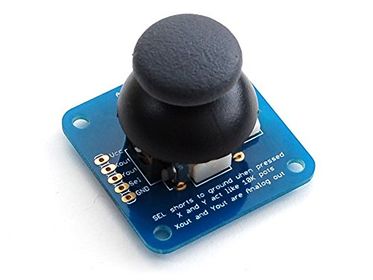
An ADA512 2-axis Analog Joystick and Button is used for controlling the movement of the launcher and shooting the ball. The data from the joystick is read using the ADC pins of the SJTwo board. The button switch is detected using a digital pin on the board.
Features of the joystick:
1. Usable with any voltage up to 5V
2. Analog outputs
3. 1 mA draw when used with 5V
4. On-board button
5. High sensitivity
Software Design & Implementation
The ADA512 joystick's device driver works on the principle that the ADC pins will be able to read the x and y values. The joystick consists of 2 inbuilt potentiometers that provide output (x and y directions) according to the way the joystick is moved.
| X values & Mapping | Y values & Mapping |
|---|---|
| 2297 (center) | 2295 (center) |
| 43 (left) | 45 (up) |
| 4095 (right) | 4090 (down) |
Steps to read joystick data:
1. Turn on the ADC Peripheral
2. Make the ADC pin operational by setting the appropriate pin functionality using the IOCON registers.
3. Set the appropriate ADC clock (12.4 MHz is the maximum clock supported by the ADC).
4. Set the ADC pin functionality as input.
5. Select the number of channels to read.
6. Select burst mode for immediate conversion.
void adc__initialize_alien(void)
{
Turn ON ADC peripheral;
make ADC operational;
set ADC clock;
Set Pin functions;
select ADC channels;
start burst mode;
}
data get_data(adc_channel_e x_port, adc_channel_e y_port, gpio_s button_press) {
data s;
s.x_data = adc__get_adc_value(x_port);
s.y_data = adc__get_adc_value(y_port);
if (gpio__get(button_press)) {
s.switch_pressed = true;
} else {
s.switch_pressed = false;
}
return s;
}
MP3 Decoder
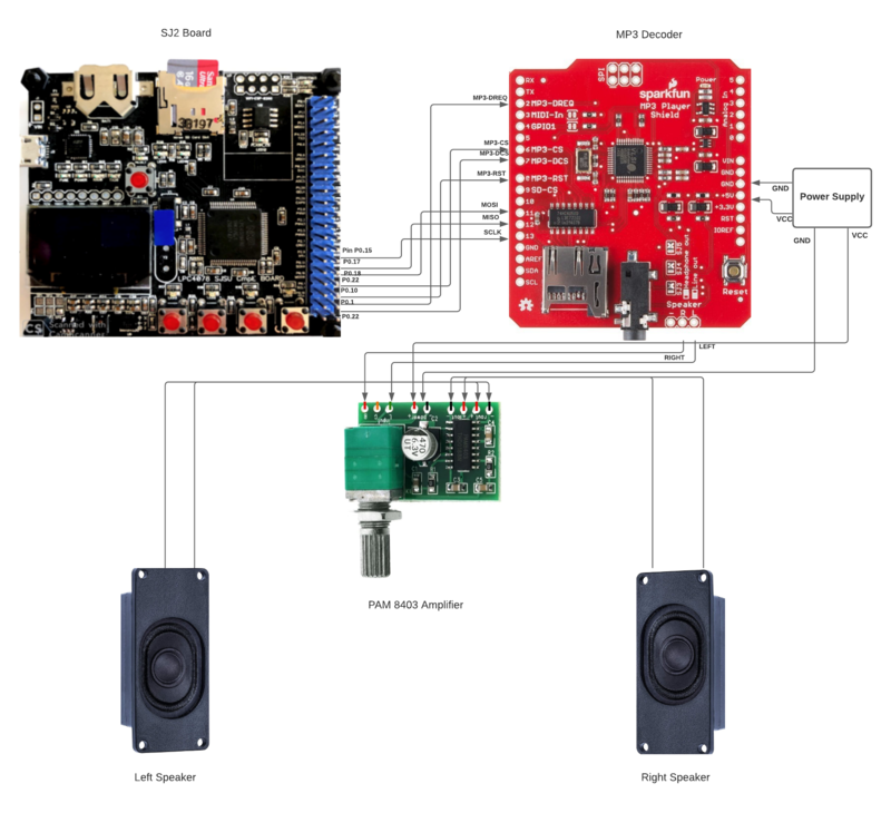
The MP3 shield communicates with the sister SJ2 board through SPI communication protocol with the SPI0 pins of the SJ2 board as follows:
| Label | Name | Function | Pin Connection | Description |
|---|---|---|---|---|
| 1 | MP3-DREQ | Decoder Data Request | Pin 0.1 | MP3 decoder signals to master to ready to receive next 32 bytes of data |
| 2 | MP3-CS | VS1053B Chip Select | Pin 0.22 | Chip select pin for MP3 decoder to be activated while sending control signals |
| 3 | MP3-DCS | VS1053B Data CS | Pin 0.0 | Data Chip Select Pin for the MP3 decoder to be activated while sending audio data signals. |
| 4 | MP3-RST | VS1053 Reset | Pin 0.10 | Reset pin for the MP3 Decoder |
| 5 | MOSI | Master Output Slave Input | Pin 0.18 | Master send data to Slave over SPI bus |
| 6 | MISO | SPI Bus (Master Input Slave Output) | Pin 0.17 | Slave send data to master over SPI bus |
| 7 | SCK | SPI Clock | Pin 0.15 | Clock generated by the master over SPI bus |
| 8 | +5V | +5V | PCB Vout | 5 Volt Input from PCB |
| 9 | GND | GND | GND | GND connected to PCB |
Hardware Design
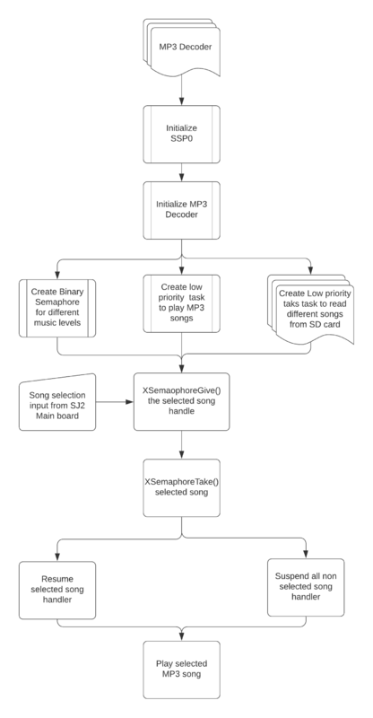
Software Design
Implementation
To initialize the MP3 decoder, we have first initialized the SSP0 and the SJ2 pins connected to the MP3 decoder with proper input/output function configurations. We then configure the decoder registers by selecting the MP3 chip select pin and writing data over SPI. These include the mode (default), clock frequency multiplier (3x), volume (max), and audio (44100 Hz stereo data). We then flush the mp3 decoder, sending it 2500 0 bytes. Reading the MP3 File from an SD Card[edit] We create a low priority task (read_song_from_sd_card) to read from the SD Card. Read_song_from_sd_card task first opens the mp3 file on the sd card and determines the size. Afterward, it reads in 512 bytes at a time to a global array (whenever the music playing task has finished playing the previous 16 bytes) and sets a global variable (sdready) to true. It will continue to do this until the file has been completely read, and then start over from the beginning.
Feeding the Decoder and Playing Music
We create another low priority task (play_song_task) to play music. If the MP3 DREQ pin is currently set, it delays. Otherwise, whenever sdready is true, it selects the Data chip select line and sends 32 bytes over the SPI bus. It then deselects data chip select and redoes this 16 times (sending the 512 bytes that have been read). After it has sent all 512 bytes, it sets sdready to false so the read_song_from_sd_card task knows to read in the next 512 bytes. It continues to repeat this process for as long as mp3sdcard reads in data to the array.
Task to read song from sd card
void read_level_1_bgm_from_sdcard(void *p) {
 vTaskSuspend(NULL);
 unsigned int ptr_to_bytes_read = 0;
 while (1) {
   const char filename_path[] = "level1.mp3";
   FIL song;
   // Open or creates a file
   FRESULT check = f_open(&song, filename_path, (FA_READ | FA_OPEN_ALWAYS));
   if (FR_OK == check) {
     f_lseek(&song, f_size(&song));
     current_position_in_mp3_file = f_tell(&song);
     current_position_in_mp3_file /= 32;
     f_lseek(&song, 0);
     mp3_file_size = 0;
     song_position = 0;
     f_read(&song, &data_buffer, BYTES_TO_READ, &ptr_to_bytes_read);
     while (mp3_file_size < current_position_in_mp3_file + 32) {
       if (song_position == 16 & sdready == false || sdready == false) {
         f_read(&song, &data_buffer, BYTES_TO_READ, &ptr_to_bytes_read);
         mp3_file_size += 16;
         song_position = 0;
         sdready = true;
       }
       vTaskDelay(1);
     }
     printf("Song finished! \n");
     f_close(&song);
     song_position = 0;
     mp3_file_size = 0;
     vTaskDelay(500);
   }
   else {
     printf("Failed to read SD card \n");
   }
   vTaskDelay(1);
  }
 }
Task to play song
void play_song_task(void *p) {
 vTaskSuspend(NULL);
 while (mp3_file_size < current_position_in_mp3_file + 32) {
   while ((song_position < 16) && (sdready == true) && (mp3_sel == 0)) {
     while (!(LPC_GPIO0->PIN & (MP3_DREQ))) {
       vTaskDelay(1);
       ;
     }
     LPC_GPIO0->CLR = (MP3_DCS);
     for (int a = 0; a < 32; a++) {
       spi0_ExchangeByte(data_buffer[a + (song_position * 32)]);
     }
     // sdready = false;
     song_position++;
     LPC_GPIO0->SET = (MP3_DCS);
     if (song_position == 16) {
       mp3_sel = 0;
       sdready = false;
     }
   }
 }
}
Binary Semaphore
We have low priority created check_which_song_recieved_from_main_sj2_board_semaphore_give which will act as a producer task which will select which mp3 background music or sound fx need to be played and it will give the semaphore of the selected music file to the high priority consumer task called play_song_task which will suspend all other song handlers and play the selected song.
Communication between Main and Sister SJ2 board
We have initialized 3 GPIO pins on the main(P0.15, P0.18, P0.1) and sister board(P2.0, P2.2, P2.5) and we have a total of 8 songs list, to which the respective GPIO pins will be high or low based on the song selection. The GPIO pins on the mainboard will be the output pins and the GPIO pins on the sister board will be the input pins. Henceforth, the sister board will receive input from the mainboard for the song selection and a binary semaphore will play the song.
LED Matrix
Hardware Design
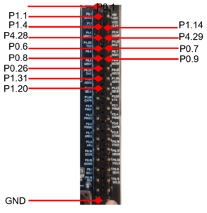
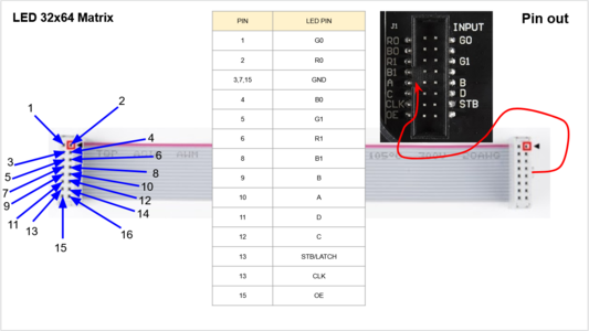
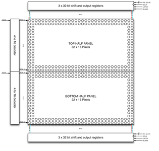
We use a 32x64 LED matrix consisting of 2048 LEDs arranged in 32 rows and 64 columns each, with each led having separate Red, Green, and Blue LED chips assembled together as a single unit. This 32x64 LED matrix is comprised of 2 of 16x32 led matrices placed vertically to each other. There are different drivers for controlling the corresponding rows and columns each. In order to illuminate a particular led, one needs to access and control the corresponding row and column (just like the coordinate-axis). To change the color of a particular led, each led must be controlled using the driver for that row and column. A layout of pins and connections can be seen below:
| LED Matrix Pins | Connection to SJTwo board |
|---|---|
| R0 | Pin 0.1 |
| G0 | Pin 1.1 |
| B0 | Pin 1.4 |
| R1 | Pin 4.28 |
| B1 | Pin 0.6 |
| G1 | Pin 0.8 |
| A | Pin 1.23 |
| B | Pin 1.29 |
| C | Pin 2.1 |
| D | Pin 2.4 |
| CLK | Pin 0.26 |
| STB | Pin 1.31 |
| OE | Pin 1.20 |
| GND | GND |
The matrix pixels are controlled by 6 drivers, 3 for the top half of the matrix(R0, G0, B0) and 3 for the bottom half(R1, G1, B1). The three drivers for R, G, and B share an SCLK, Latch, and OE signal. The top half pixels of the matrix controlled by R0, G0, B0 are rows 0-15, and the second half controlled by R1, G1, B1 are rows 16-31. The display is multiplexed at a duty cycle of 1/16, this means that one row in the top half and one row in the bottom half will be illuminated at a time. In order to display an image, the row and column LEDs for that image must be turned “ON”, therefore, the entire panel must be scanned at a rate(speed) at which it appears that the image is being displayed without flickering. To display different colors and different brightness levels, the LED chips of the corresponding row and column must be adjusted by varying the amount and time that each LED chip is turned on during each cycle.
LED Matrix Specifications
5V regulated power input, 4A max (all LEDs on)
2.1 mm x 2.1 mm LED size
1/16 Scan Rate
Software Design
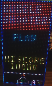
The game has 3 levels apart from the main menu, Credit scene, and Game-over screen. Just like any other arcade game, the game only starts when you earn credits and it is earned by pressing a button. The game begins with the press of another button. A block of bubbles starts falling down with every turn and finishes if it touches the danger line below. Bubbles, when hit with similar color, get destroyed and the game advances to the next level when all the bubbles on the screen are cleared. There's also a hack to traverse through levels, just press the credit score button and it will do the job for you. But hey, that's a cheat code, so you're a cheater!
RGB Color Combo
| Red | Blue | Green | Color |
|---|---|---|---|
| 0 | 0 | 0 | White |
| 0 | 0 | 1 | Blue |
| 0 | 1 | 0 | Green |
| 0 | 1 | 1 | Cyan |
| 1 | 0 | 0 | Red |
| 1 | 0 | 1 | Magenta |
| 1 | 1 | 0 | Yellow |
| 1 | 1 | 1 | Black |
Implementation
1. Initialize the LED matrix by configuring necessary pin directions. 2. Disable Output Enable (OE) GPIO before feeding matrix data. 3. Select the required row by setting bits on A, B, C, D GPIO pins. 4. Loop through the pixels (columns) in the selected row and set the pixel color on R, G, B GPIO pins. 5. Set zero on R, G, B GPIO pins to mask that particular pixel. 6. Set and Reset the clock for pushing the R, G, B bits for each column. 7. Issue latch to mark the row's completion and reset the latch before going to the next row. 8. Follow steps 2 to 7 for other rows.
for (uint8_t row = 0; row < (MAX_ROW); row++) {
     disableOE();
     set_row(row);
     for (uint8_t col = 0; col < MAX_COL; col++) {
       LPC_GPIO0->PIN |= (1 << CLK);
       set_color_bottom(game_matrix[row + (MAX_ROW / 2)][col]);
       set_color_top(game_matrix[row][col]);
       LPC_GPIO0->PIN &= ~(1 << CLK);
     }
     LPC_GPIO0->PIN |= (1 << LAT);
     enableOE();
     LPC_GPIO0->PIN &= ~(1 << LAT);
     enableOE();
     vTaskDelay(1);
}
Graphics Driver
We have managed to program the graphics in a relatively simple way by looking at the ADAFruit gfx library that comes ready to use with Arduino. Our graphics driver can implement graphics and animations such as letters, numbers, ball appearance and ball disappearance etc.
void place_launcher(LedMatrixDisplay led_display, pixel_color rgb, gfx__cursor start_cursor, bool
choose_back_frame) {
game_event object_property = BACKGROUND_OBJECT;
rgb.event = object_property;
draw_line(led_display, rgb, ROTATION_90, start_cursor, 9, choose_back_frame);
modify_pixel(led_display, rgb, start_cursor.x + 0, start_cursor.y + 1, choose_back_frame);
modify_pixel(led_display, rgb, start_cursor.x + 0, start_cursor.y + 2, choose_back_frame);
modify_pixel(led_display, rgb, start_cursor.x + 1, start_cursor.y + 3, choose_back_frame);
modify_pixel(led_display, rgb, start_cursor.x + 2, start_cursor.y + 4, choose_back_frame);
modify_pixel(led_display, rgb, start_cursor.x + 3, start_cursor.y + 5, choose_back_frame);
modify_pixel(led_display, rgb, start_cursor.x + 4, start_cursor.y + 5, choose_back_frame);
modify_pixel(led_display, rgb, start_cursor.x + 5, start_cursor.y + 5, choose_back_frame);
modify_pixel(led_display, rgb, start_cursor.x + 6, start_cursor.y + 4, choose_back_frame);
modify_pixel(led_display, rgb, start_cursor.x + 7, start_cursor.y + 3, choose_back_frame);
modify_pixel(led_display, rgb, start_cursor.x + 8, start_cursor.y + 1, choose_back_frame);
modify_pixel(led_display, rgb, start_cursor.x + 8, start_cursor.y + 2, choose_back_frame);
}
Game Engine
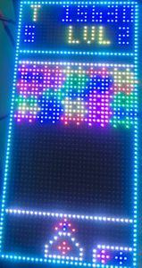
The game starts with the Main Menu, which has the number of turns, score, and Level on the top. A credit count and Ball queue are placed at the bottom of the screen. Once the credit button is pressed and credits are accumulated and the game starts by pressing the trigger button. A bubble is ready inside the trigger and the player just needs to adjust the pointer and shoot in the desired direction. Two other bubbles based on the number of colored bubbles present on the top is available in the queue. After the ball is released from the trigger it checks the property of the above objects and functions accordingly. If the released bubble encounters a border wall, then it bounces off in the opposite direction, if it encounters the bubbles then sticks to it if it's a different color, else destroys all the same colored bubbles. And finally, if the ball touches the Wall on the top then it doesn't stick but gets destroyed. The trigger remains empty and the queue still has the old bubbles. Based on the final function of the released bubble, a function scans the number of different colored bubbles in the stack and calculates the color of bubbles that are present in more. The trigger and queue then get updated with new bubbles and the wall comes down a bit further near the danger line.
The above process keeps happening until either all the bubbles are cleared, the wall reaches the danger line, or you cheat your way to the next level. Have fun playing!
Testing & Technical Challenges
As with any other project, even this threw challenges along the way.
LED Matrix
1. Understanding the matrix and then getting it to run was difficult as proper documentation or resource for the matrix was not available.
2. OE pin was not active low and it took us some time to figure it out.
3. Bubble, after released by the player, should move in the direction of the pointer and bounce off the border wall.
A graphics library was developed to print Alphanumerics in both horizontal and vertical positions. The driver was designed in a way to simply accept the coordinates of the board, shape, and color of the bubble instead of plotting it manually.
MP3 Decoder
1. Communicating with the decoder using SSP was challenging and took multiple rounds of debugging to start playing the tracks.
2. Switching between the songs when levels change also gave some issues.
Inputs from SJ2 were enabled to indicate the level change within the state machine, this way when the level changed the respective pin indicated the song to be played.
Game Design
1. First major challenge was to clear all the same colored bubbles once it was hit by the player bubble.
2. The Second challenge was to figure out an algorithm for the released bubble to either get attached or destroyed when it touches the bubble-block.
3. Designing the functionalities of border walls to bounce the released bubble, the wall to come down and destroy if the player bubble touches it, and aligning with nearby bubbles were few other challenges faced in game design.
A function that scans the bubble-block and then returns the number of different colored bubbles present was implemented to identify and destroy all the same colored bubbles. Bubbles were defined with sticky and player properties and when the player bubble encounters the sticky property, stops moving and either sticks to it or destroys it. Similarly, a wall and bounce property was defined to guide the bubble.
Future Suggestions
1. Modify a single pixel with different locations to get a thorough understanding of the led matrix. Check all the possible colors to identify any faulty pixels on the board. Write a generic scalable code to help you in the game. Implement frame methodology to prevent flickering and achieve a smooth transition of pixels.
2. Preferably use UART based MP3 decoder rather than SPI.
Conclusion
This project was a fun and strenuous application of our engineering and project management skills.
After completing the driver labs during CMPE 244, we felt confident that we could develop a driver, for the Adafruit LED matrix, without using any third-party libraries. We researched the hardware operations of the LED matrix and how to drive the RGB LED. Once we could control LEDs one at a time, the project evolved from an engineering problem into more of a creative exercise.
Overall I think the biggest lesson that we learned is project management based. We spent a lot of time choosing between various game designs and it forced us to start our final iteration later than we would have liked. However, we bonded together and worked hard, and managed to get the game working.
Project Video
Project Source Code
References
Acknowledgement
We would like to sincerely thank Professor Preetpal Kang for his all-round guidance, feedback, and support. His classroom lectures were significant in imparting knowledge on embedded systems. Further, we would like to thank the ISA team for their advice.
