Difference between revisions of "S15: Wireless Mesh Network"
Proj user8 (talk | contribs) (Created page with "=== Grading Criteria === <font color="green"> * How well is Software & Hardware Design described? * How well can this report be used to reproduce this project? * Code Quali...") |
(→Grading Criteria) |
||
| (68 intermediate revisions by one other user not shown) | |||
| Line 1: | Line 1: | ||
| − | |||
| − | |||
| − | |||
| − | |||
| − | |||
| − | |||
| − | |||
| − | |||
| − | |||
| − | |||
| − | |||
| − | |||
== Project Title == | == Project Title == | ||
Wireless Mesh Network | Wireless Mesh Network | ||
== Abstract == | == Abstract == | ||
| − | + | A mesh network topology is a design in which each node in the network is connected to at least two other nodes in the network. Communication between two nodes is established without a internet connection. Each node in the network can talk to every other node in the network by exchanging a payload data. An important feature of mesh network is that there is no single point of failure(SPoF), i.e. data is transmitted via an alternative route even if a node in the network fails. | |
| + | In this project we are implementing a wireless mesh network using Nordic wireless on SJOne boards. Each SJOne board acts as a node in the wireless mesh network. Features such as self-healing, shortest path routing, address nodes with auto-replies, and node participation are implemented to as to make the communication more reliable. | ||
== Objectives & Introduction == | == Objectives & Introduction == | ||
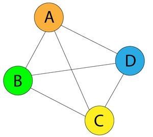
| − | The wireless mesh network is achieved through the built-in Nordic Wireless interface. Each board acts as a node in the mesh network which sends and receives information. The following objectives are to be implemented: | + | [[File:S15_wirelessmesh_fullmesh.jpg|thumb|right|text-top|Fig 1. Full mesh topology]] |
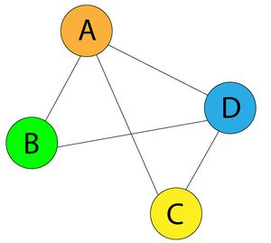
| + | [[File:S15_wirelessmesh_partialmesh.jpg|thumb|right|text-top|Fig 2. Partial mesh topology]] | ||
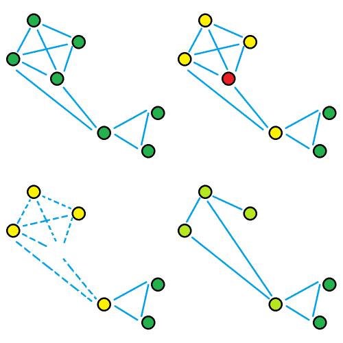
| + | [[File:S15_wirelessmesh_self_healing.gif|thumb|right|text-top|Fig 3. Self-healing demonstration]] | ||
| + | The wireless mesh network is achieved through the built-in Nordic Wireless interface. Each board acts as a node in the wireless mesh network which sends and receives information. The following objectives are to be implemented: | ||
* Self-healing | * Self-healing | ||
| − | * Shortest | + | * Shortest path routes |
| − | * Address nodes with auto- | + | * Address nodes with auto-retries |
* Each node participation | * Each node participation | ||
| + | |||
| + | Mesh networks play an important part in the Internet of Things(IoT). Mesh networks can use a full mesh topology or a partial mesh topology. In full mesh topology, each node is connected to every other node in the network and in a partial mesh topology at least one node is connected to every other node and the rest of the nodes are connected to the nodes that they frequently exchange data with. Wired mesh network pose several constraints. Each node in the network has to be physically connected to every other node. The advancement of wireless mesh networks simplifies this approach. | ||
| + | |||
| + | A ''Wireless Mesh Network(WMN)'' is a communication network made up of radio nodes organized in a mesh topology. It was originally developed for the military communication. A typical wireless mesh network consists of mesh clients, mesh routers, and gateways. In this project the SJOne boards are the mesh clients. Mesh routers route traffic from the gateways, which can happen over the internet. A mesh cloud comprises of the area covered by the radio nodes working as a single network. A mesh network is highly reliable, during transmission if a node fails, the data is sent to the other node through a redirected path. The data is transmitted from one node to other in hops through the intermediate nodes. Each intermediate nodes maintains a routing table which includes information about the network topology, destination node, source node and next hop. A routing table is a database which keeps track of the path and assists the intermediate node in delivering the information from source to the destination. | ||
| + | |||
| + | ''Self-healing'' is a technique in which a new connection is formed between the nodes in case of a failure such as a node moving out of scope due to external or internal disturbances. This ensures that the data is transmitted to the destination node through a new path even if there is any conflict in the established path. This technique is demonstrated through a gif in figure 3. The node in red is the node which is destroyed, a communication link is established between the other two nodes ensuring reliable transmission of data. | ||
| + | |||
| + | ''Shortest path routes'' is a technique in which the message from node A to node B is delivered through the shortest possible path in the network. Suppose in the mesh network shown in figure 1, if node A wants to send the data to node C, it will directly send it to C instead of routing it through B or D. | ||
| + | |||
| + | ''Address nodes with auto-retries'' is a technique in which a node re-sends the packet if it doesn't get an acknowledgement from the destination node. The number maximum number of re-transmits, delay for a single transmit and delay from one transmission to the other are fully configurable. | ||
| + | |||
| + | ''Each node participation'' is a technique through which the nodes in the network actively participate in the network to deliver the packets. This is essential for self-healing. | ||
| + | |||
=== Team Members & Responsibilities === | === Team Members & Responsibilities === | ||
1. Akhil Bhargav Josyabhatla | 1. Akhil Bhargav Josyabhatla | ||
| − | * | + | * Software implementation |
2. Dheeraj Dake | 2. Dheeraj Dake | ||
| − | * | + | * Software implementation and documentation |
3. Manideep Kurumella | 3. Manideep Kurumella | ||
| − | * | + | * Software implementation |
4. Vishnu Vardhana Reddy Mandalapu | 4. Vishnu Vardhana Reddy Mandalapu | ||
| − | * | + | * Software implementation |
== Schedule == | == Schedule == | ||
| Line 38: | Line 43: | ||
{| class="wikitable" | {| class="wikitable" | ||
|- | |- | ||
| − | ! scope="col"| Week | + | ! scope="col"| Week |
| − | ! scope="col"| | + | ! scope="col"| Dates |
| − | ! scope="col"| | + | ! scope="col"| Challenges |
| − | ! scope="col"| | + | ! scope="col"| Comments |
|- | |- | ||
! scope="row"| 1 | ! scope="row"| 1 | ||
| − | | 4/ | + | | 3/31 - 4/7 |
| − | | | + | | Mesh network overview |
| − | | Completed | + | | Completed |
| + | |- | ||
| + | ! scope="row"| 2 | ||
| + | | 4/7 - 4/14 | ||
| + | | ANT network overview | ||
| + | | Completed | ||
| + | |- | ||
| + | ! scope="row"| 3 | ||
| + | | 4/14 - 4/21 | ||
| + | | To test communication between the boards using Nordic wireless | ||
| + | | Completed | ||
| + | |- | ||
| + | ! scope="row"| 4 | ||
| + | | 4/21 - 4/28 | ||
| + | | To send packets using addressing techniques | ||
| + | | Completed | ||
| + | |- | ||
| + | ! scope="row"| 5 | ||
| + | | 4/28 - 5/5 | ||
| + | | To test the shortest path using all possible configurations | ||
| + | | Completed | ||
| + | |- | ||
| + | ! scope="row"| 6 | ||
| + | | 5/5 - 5/12 | ||
| + | | Implement self healing and re-transmission mechanisms | ||
| + | | Completed | ||
| + | |- | ||
| + | ! scope="row"| 7 | ||
| + | | 5/12 - 5/19 | ||
| + | | Testing | ||
| + | | Completed | ||
| + | |- | ||
| + | ! scope="row"| 8 | ||
| + | | 5/19 - 5/25 | ||
| + | | More testing and final demo | ||
| + | | Completed | ||
|} | |} | ||
| Line 57: | Line 97: | ||
! scope="col"| Price | ! scope="col"| Price | ||
|- | |- | ||
| − | + | | scope="row"| SJ One Board | |
| $80 | | $80 | ||
| 4 | | 4 | ||
| $320 | | $320 | ||
| + | |- | ||
| + | | scope="row"| Antenna | ||
| + | | $3 | ||
| + | | 4 | ||
| + | | $12 | ||
| + | |- | ||
| + | | scope="row" | Total | ||
| + | | | ||
| + | | | ||
| + | ! $332 | ||
|} | |} | ||
| + | == Design & Implementation == | ||
| − | |||
| − | |||
=== Hardware Design === | === Hardware Design === | ||
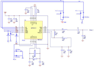
| − | + | Wireless mesh network is achieved using Nordic nRF24L01 transceiver. The hardware schematic of the chip is taken from the datasheet. The pins CE, SCN, SCK, MOSI, MISO and IRQ are connected to the CPU pins. The electrical connections between the CPU and wireless transceiver are taken from ''SJOne_lpc1758_rev4.pdf''. The detailed hardware schematic is shown in figure 4. The block diagram of nRF24L01 from the datasheet is shown in figure 5. The nordic wireless chip is shown in the figure 6. Each SJOne board connected to the laptop as as a node. | |
| + | [[File:S15_wirelessmesh_nordic_hardware.jpg|400px|thumb|left|text-top|Fig 4. Hardware Schematic of nRF24L01]] | ||
| + | [[File:S15_wirelessmesh_nordic_blockdiagram.png|600px|thumb|right|text-top|Fig 5. Block diagram of nRF24L01]] | ||
| + | [[File:S15_wirelessmesh_nordic_SJONe_board.gif|600px|thumb|right|text-top|Fig 6. SJOne board with nordic wireless]] | ||
| + | |||
| + | |||
| + | |||
| + | |||
| + | |||
| + | |||
| + | |||
| + | |||
| + | |||
| + | |||
| + | |||
| + | |||
| + | |||
| + | |||
| + | |||
| + | |||
| + | |||
| + | |||
| + | |||
| + | |||
| + | |||
| + | |||
| + | |||
| + | |||
| + | |||
| + | |||
| + | |||
| + | |||
| + | |||
| + | |||
| + | |||
| + | |||
| + | |||
| + | |||
| + | |||
| + | |||
| + | |||
| + | |||
| + | |||
| + | |||
| + | |||
| + | |||
| + | |||
| + | |||
| + | |||
| + | |||
| + | |||
| + | |||
| + | |||
| + | |||
| + | |||
| + | |||
| + | |||
| + | |||
| + | |||
| + | |||
| + | |||
| + | |||
| + | |||
=== Hardware Interface === | === Hardware Interface === | ||
| − | + | The hardware interface consists of 4 SJOne boards that are powered via laptops through a USB. Antennas are attached for increasing the wireless range. The nordic wireless communicates with the LPC 1769 CPU via SPI bus. The pins that are used for establishing the communication between the nordic wireless and CPU are shown in the table below. | |
| − | === | + | {| class="wikitable" |
| − | + | |- | |
| + | ! scope="col"| Nordic pins | ||
| + | ! scope="col"| CPU pins | ||
| + | ! scope="col"| Description | ||
| + | |- | ||
| + | | scope="row"| CE | ||
| + | | P1.24 | ||
| + | | Chip enable activates RX or TX mode | ||
| + | |- | ||
| + | | scope="row"| CSN | ||
| + | | P0.16 | ||
| + | | SPI Chip select | ||
| + | |- | ||
| + | | scope="row" | SCK | ||
| + | | P0.15 | ||
| + | | SPI Clock | ||
| + | |- | ||
| + | | scope="row" | MOSI | ||
| + | | P0.18 | ||
| + | | SPI Slave Data Input | ||
| + | |- | ||
| + | | scope="row" | MISO | ||
| + | | P0.17 | ||
| + | | SPI Slave Data Output, with tri-state option | ||
| + | |- | ||
| + | | scope="row" | IRQ | ||
| + | | P0.22 | ||
| + | | Maskable interrupt pin, active low | ||
| + | |} | ||
| + | |||
| + | An air data rate of 2Mbps is chosen for sending and receiving the data between the boards. Nordic wireless nRF24l01+ uses GFSK which is ''Gaussian Frequency Shift Keying'' which is a technique in which the positive and negative frequency deviations are smoothed by a Gaussian filter. This technique reduces the spectral width, making the effective bandwidth smaller which improves the quality of the transmitted signal. This ensures that the channels intersymbol interference is under control. In RF its sole purpose is to make the signal fit in its frequency band. | ||
| + | |||
| + | |||
| + | |||
| + | === Software Design === | ||
| + | [[File:S15_wirelessmesh_software_hierarchy.png|300px|thumb|right|text-top|Fig 7. Software Hierarchy for wireless mesh network]] | ||
| + | |||
| + | The wireless mesh network we are designing follows the software hierarchy mentioned in figure 6. It has 4 layers. The upper level layer being the ''mesh layer'' and the lower level being the ''hardware layer''. | ||
| + | |||
| + | '''1. Mesh Layer''' | ||
| + | This is a high level layer. The routing tables needed to maintain the source address and hop count, macros and other initialization's are defined in this layer. The network discovery is done in this layer. The packet is formed and sent from this layer to the lower layers. This layer takes care of the packet collision and implements self-healing, shortest path techniques for reliable communication between the nodes. It features automatic re-transmission of the packets in case of NACK. The number of auto retries are user configurable. | ||
| + | |||
| + | '''2. Packet Layer''' | ||
| + | This layer defines the interface between Nordic and mesh layer to receive and send packets. it receives 32 bytes data from lower layer and passes to upper layer and vice versa. It is also responsible to Nordic RF module. The nordic chip is initialized in this layer. The send and receive functions are implemented in this layer. The send function takes data and length as arguments and passes them to the Nordic. The receive function receives data and length from Nordic. | ||
| + | |||
| + | '''3. Nordic Layer''' | ||
| + | This layer is responsible for exchanging the data packets through the SPI bus with the hardware layer for transmission. This layer sets the air data rate, channel frequency and payload. The operating modes of the Nordic wireless are implemented in this layer. | ||
| + | |||
| + | '''4. Hardware Layer''' | ||
| + | This is the lower most layer in the hierarchy and initializes the nRF24L01+ transreceiver. The respective board I/O for the Nordic wireless are set and the SPI bus interface is initialized. The hardware layer is responsible for the transmission of the packets over the air between the nodes for communication. | ||
=== Implementation === | === Implementation === | ||
| − | + | [[File:S15_wirelessmesh_software_flow_code.png|500px|thumb|right|text-top|Fig 8. Mesh layer implementation]] | |
| + | The nRF24L01+ is a single chip transceiver which operates on a ISM frequency in the range 2.400-2.4835 GHz. It is connected to the LPC 1758 using the electrical specifications in the figure 4. The communication between the CPU and transceiver is established via the SPI bus. The internal FIFO’s ensure a smooth data flow between the radio front end and the systems MCU. It uses GFSK(Gaussian Frequency Shift Keying) modulation. In this project an air data rate of 1 Mbps is chosen. Each node is given a unique address so as to distinguish one from another. An RF channel frequency of 2.400 GHz is chosen for communication. The Nordic wireless has three 32 bytes tx and rx FIFO’s. The ANT pins provide a balanced RF output to the antenna. | ||
| + | |||
| + | |||
| + | In a mesh network multiple nodes transmit data simultaneously. The data is constantly exchanged between the nodes. Since all the nodes exchange the data on the same frequency, this creates collisions. To avoid collision in our mesh network, ALOHA protocol is used. The idea behind ALOHA is that, let the nodes transmit their packets at once and let there be collisions. If a collision occurs, the packets which are lost are re-transmitted after a random amount of time. The packet transmission will be eventually successful. The mesh layer is implemented as per the software hierarchy shown in figure 7. The definition of each function is explained below. | ||
| + | |||
| + | |||
| + | 1. mesh_init() | ||
| + | * The routing tables are initialized here. It initially broadcasts hello packets to determine the nodes which are in its communication range. | ||
| + | 2. mesh_service() | ||
| + | * This is the high level layer which deals with the transmission and reception of packet. It calls ''process_data packet()'' and ''process_hello_packet()'' according to the received packet type. | ||
| + | 3. process_data_packet() | ||
| + | * This processes the data packet and checks whether the address in the packet is equal to the address of the node which received it. If there is a match the node keeps the packet and the transmission ends, otherwise it broadcasts the packets to the nodes within the next hop count. | ||
| + | 4. process_hello_packet() | ||
| + | * This processes the hello packet which is used to determine all the nodes in its communication range. The routing table gets updated if there is a node malfunction. | ||
| + | 5. frame_data_packet() | ||
| + | * This contains a command handler which asks the user to enter the destination node address to which the data is to be sent. It then frames the packet according to the payload and sends the packet to the destination using the route table. | ||
| + | 6. frame_hello_packet() | ||
| + | * It sends the routing information into the payload and broadcasts it. | ||
| + | |||
| + | |||
| + | ==== Packet Frame ==== | ||
| + | [[File:S15_wirelessmesh_packet_frame.png|700px|thumb|right|text-top|Fig 9. Wireless packet frame]] | ||
| + | The wireless packet frame is shown in figure 9. The packet frame is 32 bytes in length. It consists of a source address, destination address, hop address and data length which are 1 byte each and a 28 byte payload. To represent the payload length 7 bits are enough and MSB bit in length using to indicate whether we required an ack or not. The source address is the address of the transmitting node, the destination address is address of the destination node, hop address is the address of the next node which receives the data, the length field specifies the length of the transmitting data and the rest is the payload which is 28 bytes. | ||
| + | |||
| + | Both ''hello_packet()'' and ''data_packet()'' will have the same packet frame format. A significant thing to be noticed is that, ''hello_packet()'' will have its destination address as broadcast address i.e. 0xFF since it is used to locate the nodes which are in its communication range. | ||
| + | |||
| + | ==== Routing Table ==== | ||
| + | [[File:S15_wirelessmesh_routing_table.png|300px|thumb|right|text-top|Fig 10. Routing table]] | ||
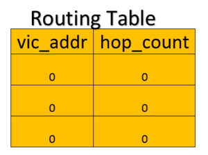
| + | A routing table is defined as a struct which consists of 2 fields. The first field is vic_addr which stores the address of the nodes in its vicinity and the second field is hop_count which stores the number of hops needed to reach the destination node. ''vic_addr'' and ''hop_count'' are 2 arrays of size 3 since the maximum number of possible nodes in the vicinity of a node in a mesh network with 4 nodes is 3. Initially all the routing table fields are 0. A routing table is shown in figure 10. | ||
| + | |||
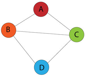
| + | The following demonstrates how the routing table works. Suppose we have a partial mesh network topology as shown in the figure 11. A is connected to B and C but not to D, B is connected to A, C and D, C is connected to A, B and D, and D is connected to B and C but not A. A message from A to D should either go through B or C. Initially the routing tables of all the nodes are empty as shown in figure 10. When the mesh is initialized, each nodes broadcasts a ''hello_packet'', which is received by all the nodes in its vicinity. A routing table can be updated in 2 ways - using source address or payload. | ||
| + | |||
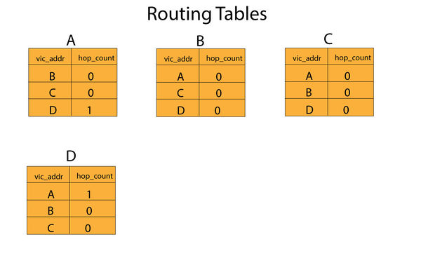
| + | The nodes which receive the packet updates the information about the source node using its source address in their routing tables. Suppose if A broadcasts the frame, nodes B and C which are in its vicinity receives the frame and updates that A is in their vicinity in their routing table. Similarly, the other nodes updates their routing tables. When a node in its vicinity broadcasts a frame, the hop count is set to 0 else it updates it from the payload information to 1. A hop count of 0 indicates that the next address is the destination address and a hop count of 1 indicates that the destination address is 1 hop away. The final routing tables of all the nodes is shown in figure 12. | ||
| + | [[File:S15_wirelessmesh_partial_route_demo.jpg|300px|thumb|left|text-top|Fig 11. Partial mesh topo]] | ||
| + | [[File:S15_wirelessmesh_final_route_demo.jpg|600px|thumb|left|text-top|Fig 12. Updated routing tables]] | ||
| + | |||
| + | |||
| + | |||
| + | |||
| + | |||
| + | |||
| + | |||
| + | |||
| + | |||
| + | |||
| + | |||
| + | |||
| + | |||
| + | |||
| + | |||
| + | |||
| + | |||
| + | |||
| + | |||
| + | |||
| + | |||
| + | |||
| + | |||
| + | |||
| + | |||
| + | |||
| + | |||
| + | |||
| + | |||
| + | |||
| + | |||
| + | |||
| + | |||
| + | |||
| + | |||
| + | |||
| + | |||
| + | |||
| + | |||
| + | |||
| + | |||
| + | |||
| + | |||
| + | |||
| + | |||
| + | |||
| + | |||
| + | |||
| + | |||
| + | |||
| + | |||
| + | |||
| + | |||
| + | |||
| + | |||
| + | |||
| + | |||
| + | |||
| + | |||
| + | |||
| + | |||
| + | ==== Command Handler ==== | ||
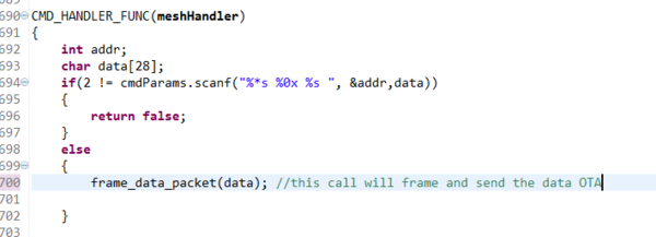
| + | A command handler is defined to send the data to a particular node in the mesh. The command for executing this command handler is ''mesh_send''. When this command is typed into the command handler, it asks for destination address and the data to be sent to the node. The data size that can be transmitted is 28 bytes. Anything exceeding that will be discarded. The command handler function is shown in figure 13. | ||
| + | [[File:S15_wirelessmesh_command_handler.png|600px|thumb|left|text-top|Fig 13. Command handler function mesh_send]] | ||
| + | |||
| + | |||
| + | |||
| + | |||
| + | |||
| + | |||
| + | |||
| + | |||
| + | |||
| + | |||
| + | |||
| + | |||
| + | |||
| + | |||
| + | |||
| + | |||
| + | |||
| + | |||
| + | |||
| + | |||
| + | |||
| + | |||
== Testing & Technical Challenges == | == Testing & Technical Challenges == | ||
| − | + | A lot of technical milestones had to be overcome in order to implement the wireless mesh successfully. The following are the technical challenges which we faced while implementing the wireless mesh network. | |
| − | + | ||
| + | === My Issue 1=== | ||
| + | Q. No packet transmission through wireless even with an antenna! | ||
| + | |||
| + | A. Make sure you run the wireless service | ||
| + | |||
| + | === My Issue 2=== | ||
| + | Q. How do you avoid collision between the packets transmitting using the same channel? | ||
| + | |||
| + | A. Implement ALOHA protocol | ||
| + | |||
| + | === My Issue 3=== | ||
| + | Q. How to avoid packet duplication when all nodes transmit the data at the same time? | ||
| + | |||
| + | A. Introduce hop address in the packet frame which acts as a software mesh | ||
| − | + | === My Issue 4=== | |
| + | Q. How to get the next hop address and update it in the routing table? | ||
| − | + | A. Getting the next hop address was challenging which was finally achieved using the proposed algorithm | |
| − | |||
== Conclusion == | == Conclusion == | ||
Conclude your project here. You can recap your testing and problems. You should address the "so what" part here to indicate what you ultimately learnt from this project. How has this project increased your knowledge? | Conclude your project here. You can recap your testing and problems. You should address the "so what" part here to indicate what you ultimately learnt from this project. How has this project increased your knowledge? | ||
| + | |||
| + | A wireless mesh network has been designed using 4 SJOne boards each acting as a node. The communication between the nodes is successfully established. A packet frame and routing tables designed. The routing tables are updated dynamically to find the shortest path in the network to transmit the data. We learned a lot about wireless mesh network and ALOHA protocol. We learned how to implement a software application layer with an existing software driver for a hardware(linking). | ||
| + | |||
| + | This project helped me learn how a wireless mesh network can exchange data between the layers and successfully communicate without any collisions. I also learned how to avoid collisions among the packets and keep track of the existing nodes in the network. | ||
=== Project Video === | === Project Video === | ||
| − | + | * [Video https://www.youtube.com/watch?v=BIvgpCmPtsc&feature=youtu.be] | |
=== Project Source Code === | === Project Source Code === | ||
| Line 99: | Line 398: | ||
== References == | == References == | ||
=== Acknowledgement === | === Acknowledgement === | ||
| − | + | We sincerely thank Prof. Preet for teaching FreeRTOS and clearing queries regarding the project. We thank all our friends who helped towards making this project. | |
=== References Used === | === References Used === | ||
| − | + | 1. https://www.sparkfun.com/datasheets/Components/SMD/nRF24L01Pluss_Preliminary_Product_Specification_v1_0.pdf | |
| + | |||
| + | 2. LPC1758 datasheet | ||
| + | |||
| + | 3. Computer networks - Tanenbaum | ||
| + | |||
| + | 4. Preet's mesh implementation and wiki page | ||
=== Appendix === | === Appendix === | ||
You can list the references you used. | You can list the references you used. | ||
Latest revision as of 15:23, 27 May 2015
Contents
Project Title
Wireless Mesh Network
Abstract
A mesh network topology is a design in which each node in the network is connected to at least two other nodes in the network. Communication between two nodes is established without a internet connection. Each node in the network can talk to every other node in the network by exchanging a payload data. An important feature of mesh network is that there is no single point of failure(SPoF), i.e. data is transmitted via an alternative route even if a node in the network fails. In this project we are implementing a wireless mesh network using Nordic wireless on SJOne boards. Each SJOne board acts as a node in the wireless mesh network. Features such as self-healing, shortest path routing, address nodes with auto-replies, and node participation are implemented to as to make the communication more reliable.
Objectives & Introduction
The wireless mesh network is achieved through the built-in Nordic Wireless interface. Each board acts as a node in the wireless mesh network which sends and receives information. The following objectives are to be implemented:
- Self-healing
- Shortest path routes
- Address nodes with auto-retries
- Each node participation
Mesh networks play an important part in the Internet of Things(IoT). Mesh networks can use a full mesh topology or a partial mesh topology. In full mesh topology, each node is connected to every other node in the network and in a partial mesh topology at least one node is connected to every other node and the rest of the nodes are connected to the nodes that they frequently exchange data with. Wired mesh network pose several constraints. Each node in the network has to be physically connected to every other node. The advancement of wireless mesh networks simplifies this approach.
A Wireless Mesh Network(WMN) is a communication network made up of radio nodes organized in a mesh topology. It was originally developed for the military communication. A typical wireless mesh network consists of mesh clients, mesh routers, and gateways. In this project the SJOne boards are the mesh clients. Mesh routers route traffic from the gateways, which can happen over the internet. A mesh cloud comprises of the area covered by the radio nodes working as a single network. A mesh network is highly reliable, during transmission if a node fails, the data is sent to the other node through a redirected path. The data is transmitted from one node to other in hops through the intermediate nodes. Each intermediate nodes maintains a routing table which includes information about the network topology, destination node, source node and next hop. A routing table is a database which keeps track of the path and assists the intermediate node in delivering the information from source to the destination.
Self-healing is a technique in which a new connection is formed between the nodes in case of a failure such as a node moving out of scope due to external or internal disturbances. This ensures that the data is transmitted to the destination node through a new path even if there is any conflict in the established path. This technique is demonstrated through a gif in figure 3. The node in red is the node which is destroyed, a communication link is established between the other two nodes ensuring reliable transmission of data.
Shortest path routes is a technique in which the message from node A to node B is delivered through the shortest possible path in the network. Suppose in the mesh network shown in figure 1, if node A wants to send the data to node C, it will directly send it to C instead of routing it through B or D.
Address nodes with auto-retries is a technique in which a node re-sends the packet if it doesn't get an acknowledgement from the destination node. The number maximum number of re-transmits, delay for a single transmit and delay from one transmission to the other are fully configurable.
Each node participation is a technique through which the nodes in the network actively participate in the network to deliver the packets. This is essential for self-healing.
Team Members & Responsibilities
1. Akhil Bhargav Josyabhatla
- Software implementation
2. Dheeraj Dake
- Software implementation and documentation
3. Manideep Kurumella
- Software implementation
4. Vishnu Vardhana Reddy Mandalapu
- Software implementation
Schedule
Show a simple table or figures that show your scheduled as planned before you started working on the project. Then in another table column, write down the actual schedule so that readers can see the planned vs. actual goals. The point of the schedule is for readers to assess how to pace themselves if they are doing a similar project.
| Week | Dates | Challenges | Comments |
|---|---|---|---|
| 1 | 3/31 - 4/7 | Mesh network overview | Completed |
| 2 | 4/7 - 4/14 | ANT network overview | Completed |
| 3 | 4/14 - 4/21 | To test communication between the boards using Nordic wireless | Completed |
| 4 | 4/21 - 4/28 | To send packets using addressing techniques | Completed |
| 5 | 4/28 - 5/5 | To test the shortest path using all possible configurations | Completed |
| 6 | 5/5 - 5/12 | Implement self healing and re-transmission mechanisms | Completed |
| 7 | 5/12 - 5/19 | Testing | Completed |
| 8 | 5/19 - 5/25 | More testing and final demo | Completed |
Parts List & Cost
| Item | Price | Quantity | Price |
|---|---|---|---|
| SJ One Board | $80 | 4 | $320 |
| Antenna | $3 | 4 | $12 |
| Total | $332 |
Design & Implementation
Hardware Design
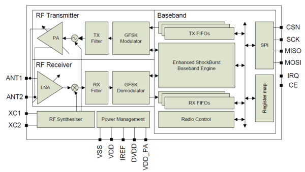
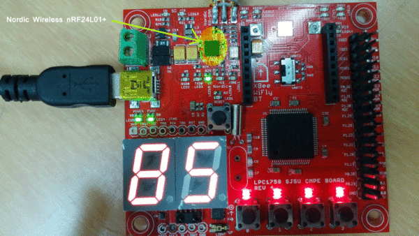
Wireless mesh network is achieved using Nordic nRF24L01 transceiver. The hardware schematic of the chip is taken from the datasheet. The pins CE, SCN, SCK, MOSI, MISO and IRQ are connected to the CPU pins. The electrical connections between the CPU and wireless transceiver are taken from SJOne_lpc1758_rev4.pdf. The detailed hardware schematic is shown in figure 4. The block diagram of nRF24L01 from the datasheet is shown in figure 5. The nordic wireless chip is shown in the figure 6. Each SJOne board connected to the laptop as as a node.
Hardware Interface
The hardware interface consists of 4 SJOne boards that are powered via laptops through a USB. Antennas are attached for increasing the wireless range. The nordic wireless communicates with the LPC 1769 CPU via SPI bus. The pins that are used for establishing the communication between the nordic wireless and CPU are shown in the table below.
| Nordic pins | CPU pins | Description |
|---|---|---|
| CE | P1.24 | Chip enable activates RX or TX mode |
| CSN | P0.16 | SPI Chip select |
| SCK | P0.15 | SPI Clock |
| MOSI | P0.18 | SPI Slave Data Input |
| MISO | P0.17 | SPI Slave Data Output, with tri-state option |
| IRQ | P0.22 | Maskable interrupt pin, active low |
An air data rate of 2Mbps is chosen for sending and receiving the data between the boards. Nordic wireless nRF24l01+ uses GFSK which is Gaussian Frequency Shift Keying which is a technique in which the positive and negative frequency deviations are smoothed by a Gaussian filter. This technique reduces the spectral width, making the effective bandwidth smaller which improves the quality of the transmitted signal. This ensures that the channels intersymbol interference is under control. In RF its sole purpose is to make the signal fit in its frequency band.
Software Design
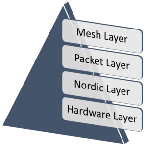
The wireless mesh network we are designing follows the software hierarchy mentioned in figure 6. It has 4 layers. The upper level layer being the mesh layer and the lower level being the hardware layer.
1. Mesh Layer This is a high level layer. The routing tables needed to maintain the source address and hop count, macros and other initialization's are defined in this layer. The network discovery is done in this layer. The packet is formed and sent from this layer to the lower layers. This layer takes care of the packet collision and implements self-healing, shortest path techniques for reliable communication between the nodes. It features automatic re-transmission of the packets in case of NACK. The number of auto retries are user configurable.
2. Packet Layer This layer defines the interface between Nordic and mesh layer to receive and send packets. it receives 32 bytes data from lower layer and passes to upper layer and vice versa. It is also responsible to Nordic RF module. The nordic chip is initialized in this layer. The send and receive functions are implemented in this layer. The send function takes data and length as arguments and passes them to the Nordic. The receive function receives data and length from Nordic.
3. Nordic Layer This layer is responsible for exchanging the data packets through the SPI bus with the hardware layer for transmission. This layer sets the air data rate, channel frequency and payload. The operating modes of the Nordic wireless are implemented in this layer.
4. Hardware Layer This is the lower most layer in the hierarchy and initializes the nRF24L01+ transreceiver. The respective board I/O for the Nordic wireless are set and the SPI bus interface is initialized. The hardware layer is responsible for the transmission of the packets over the air between the nodes for communication.
Implementation
The nRF24L01+ is a single chip transceiver which operates on a ISM frequency in the range 2.400-2.4835 GHz. It is connected to the LPC 1758 using the electrical specifications in the figure 4. The communication between the CPU and transceiver is established via the SPI bus. The internal FIFO’s ensure a smooth data flow between the radio front end and the systems MCU. It uses GFSK(Gaussian Frequency Shift Keying) modulation. In this project an air data rate of 1 Mbps is chosen. Each node is given a unique address so as to distinguish one from another. An RF channel frequency of 2.400 GHz is chosen for communication. The Nordic wireless has three 32 bytes tx and rx FIFO’s. The ANT pins provide a balanced RF output to the antenna.
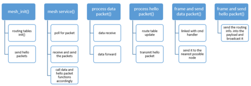
In a mesh network multiple nodes transmit data simultaneously. The data is constantly exchanged between the nodes. Since all the nodes exchange the data on the same frequency, this creates collisions. To avoid collision in our mesh network, ALOHA protocol is used. The idea behind ALOHA is that, let the nodes transmit their packets at once and let there be collisions. If a collision occurs, the packets which are lost are re-transmitted after a random amount of time. The packet transmission will be eventually successful. The mesh layer is implemented as per the software hierarchy shown in figure 7. The definition of each function is explained below.
1. mesh_init()
- The routing tables are initialized here. It initially broadcasts hello packets to determine the nodes which are in its communication range.
2. mesh_service()
- This is the high level layer which deals with the transmission and reception of packet. It calls process_data packet() and process_hello_packet() according to the received packet type.
3. process_data_packet()
- This processes the data packet and checks whether the address in the packet is equal to the address of the node which received it. If there is a match the node keeps the packet and the transmission ends, otherwise it broadcasts the packets to the nodes within the next hop count.
4. process_hello_packet()
- This processes the hello packet which is used to determine all the nodes in its communication range. The routing table gets updated if there is a node malfunction.
5. frame_data_packet()
- This contains a command handler which asks the user to enter the destination node address to which the data is to be sent. It then frames the packet according to the payload and sends the packet to the destination using the route table.
6. frame_hello_packet()
- It sends the routing information into the payload and broadcasts it.
Packet Frame
The wireless packet frame is shown in figure 9. The packet frame is 32 bytes in length. It consists of a source address, destination address, hop address and data length which are 1 byte each and a 28 byte payload. To represent the payload length 7 bits are enough and MSB bit in length using to indicate whether we required an ack or not. The source address is the address of the transmitting node, the destination address is address of the destination node, hop address is the address of the next node which receives the data, the length field specifies the length of the transmitting data and the rest is the payload which is 28 bytes.
Both hello_packet() and data_packet() will have the same packet frame format. A significant thing to be noticed is that, hello_packet() will have its destination address as broadcast address i.e. 0xFF since it is used to locate the nodes which are in its communication range.
Routing Table
A routing table is defined as a struct which consists of 2 fields. The first field is vic_addr which stores the address of the nodes in its vicinity and the second field is hop_count which stores the number of hops needed to reach the destination node. vic_addr and hop_count are 2 arrays of size 3 since the maximum number of possible nodes in the vicinity of a node in a mesh network with 4 nodes is 3. Initially all the routing table fields are 0. A routing table is shown in figure 10.
The following demonstrates how the routing table works. Suppose we have a partial mesh network topology as shown in the figure 11. A is connected to B and C but not to D, B is connected to A, C and D, C is connected to A, B and D, and D is connected to B and C but not A. A message from A to D should either go through B or C. Initially the routing tables of all the nodes are empty as shown in figure 10. When the mesh is initialized, each nodes broadcasts a hello_packet, which is received by all the nodes in its vicinity. A routing table can be updated in 2 ways - using source address or payload.
The nodes which receive the packet updates the information about the source node using its source address in their routing tables. Suppose if A broadcasts the frame, nodes B and C which are in its vicinity receives the frame and updates that A is in their vicinity in their routing table. Similarly, the other nodes updates their routing tables. When a node in its vicinity broadcasts a frame, the hop count is set to 0 else it updates it from the payload information to 1. A hop count of 0 indicates that the next address is the destination address and a hop count of 1 indicates that the destination address is 1 hop away. The final routing tables of all the nodes is shown in figure 12.
Command Handler
A command handler is defined to send the data to a particular node in the mesh. The command for executing this command handler is mesh_send. When this command is typed into the command handler, it asks for destination address and the data to be sent to the node. The data size that can be transmitted is 28 bytes. Anything exceeding that will be discarded. The command handler function is shown in figure 13.
Testing & Technical Challenges
A lot of technical milestones had to be overcome in order to implement the wireless mesh successfully. The following are the technical challenges which we faced while implementing the wireless mesh network.
My Issue 1
Q. No packet transmission through wireless even with an antenna!
A. Make sure you run the wireless service
My Issue 2
Q. How do you avoid collision between the packets transmitting using the same channel?
A. Implement ALOHA protocol
My Issue 3
Q. How to avoid packet duplication when all nodes transmit the data at the same time?
A. Introduce hop address in the packet frame which acts as a software mesh
My Issue 4
Q. How to get the next hop address and update it in the routing table?
A. Getting the next hop address was challenging which was finally achieved using the proposed algorithm
Conclusion
Conclude your project here. You can recap your testing and problems. You should address the "so what" part here to indicate what you ultimately learnt from this project. How has this project increased your knowledge?
A wireless mesh network has been designed using 4 SJOne boards each acting as a node. The communication between the nodes is successfully established. A packet frame and routing tables designed. The routing tables are updated dynamically to find the shortest path in the network to transmit the data. We learned a lot about wireless mesh network and ALOHA protocol. We learned how to implement a software application layer with an existing software driver for a hardware(linking).
This project helped me learn how a wireless mesh network can exchange data between the layers and successfully communicate without any collisions. I also learned how to avoid collisions among the packets and keep track of the existing nodes in the network.
Project Video
Project Source Code
References
Acknowledgement
We sincerely thank Prof. Preet for teaching FreeRTOS and clearing queries regarding the project. We thank all our friends who helped towards making this project.
References Used
2. LPC1758 datasheet
3. Computer networks - Tanenbaum
4. Preet's mesh implementation and wiki page
Appendix
You can list the references you used.
