Difference between revisions of "S16: Laser Harp"
Proj user20 (talk | contribs) (→Hardware Interface) |
Proj user20 (talk | contribs) (→Hardware Interface) |
||
| Line 204: | Line 204: | ||
We don't have a dedicated GPIO driver so each pin is initialized as GPIO and either input or output. Chip selects are set as outputs, with functions to clear and set bits. The push buttons are set as input and checked for when they are high to tell the board that an action must be taken. The chip selects for the MIDI and the ADC are toggled before and after each transaction. | We don't have a dedicated GPIO driver so each pin is initialized as GPIO and either input or output. Chip selects are set as outputs, with functions to clear and set bits. The push buttons are set as input and checked for when they are high to tell the board that an action must be taken. The chip selects for the MIDI and the ADC are toggled before and after each transaction. | ||
| − | For ADC Communication over the SPI0 bus, seven photodiode circuits are wired to channels 1-7 on the MCP3008. The photodiode circuit produces a varying analog voltage that will be converted to a digital value. In order to calibrate whether the beam is cut, Freertos is used to display and record the digital value while the IR diode is activating the photodiode, and when the beam to the photodiode is cut. We found that the digital value is lower when the beam the cut. Logically the program has to use an statement that works as follows: if (ch_n < 850) qSendToMidi(). | + | For ADC Communication over the SPI0 bus, seven photodiode circuits are wired to channels 1-7 on the MCP3008. The photodiode circuit produces a varying analog voltage that will be converted to a digital value. In order to calibrate whether the beam is cut, Freertos is used to display and record the digital value while the IR diode is activating the photodiode, and when the beam to the photodiode is cut. We found that the digital value is lower when the beam the cut. Logically the program has to use an statement that works as follows: if (ch_n < 850) qSendToMidi(). That will activate the midi task to play the note. |
| + | |||
| + | For the IR diode, we sourced 5V from a LM7805. The motivation for the 5V was to ensure that the IR diodes emit the necessary radiation to create a noticeable change in the photodiode. For the photodiode, we were only able to get a stable voltage from the SJOne board. | ||
=== Software Design === | === Software Design === | ||
Revision as of 05:56, 25 May 2016
Contents
Grading Criteria
- How well is Software & Hardware Design described?
- How well can this report be used to reproduce this project?
- Code Quality
- Overall Report Quality:
- Software Block Diagrams
- Hardware Block Diagrams
- Schematic Quality
- Quality of technical challenges and solutions adopted.
Laser Harp
Abstract
Our plan is to design a budget version of a laser harp. This can be accomplished using infrared LEDs and infrared sensitive photodiodes. The two diode system will emulate strings of a harp. When the infrared sensor has detected an note that is played, the microcontroller will read the input from the ADC and send out a control signal to the MIDI board and the corresponding sound will play from the speaker. Controls include changing the loudness of the speaker.
Objectives & Introduction
The objective of this project is to design and build a harp that plays a note when you run your hand over the strings. Instead of a real string, a pair of IR emitter and photodiode emulates the action. This project uses seven pairs of IR emitters and photodiodes, a real-time audio decoder, and is programmed in the FreeRTOS environment.
1. Read multiple sensors through ADC.
2. Write tasks in software that handle reading values from the ADC and playing notes with the MIDI decoder.
3. Build a wooden frame and mount sensors.
4. Create a circuit to power 5V and 3.3V to system.
Team Members & Responsibilities
- Abraham Carrillo
- Sensor Circuit Design
- Interfacing/Programming Sensors with ADC
- Frame Assembly
- Kristen Kan
- Interfacing/Programming MIDI with SJ One Board/Sensors
- Power Supply Circuit Design
Schedule
| Week# | Date | Task | Status | Notes |
|---|---|---|---|---|
| 1 | 4/3 | Finalize following circuit designs and order parts
1. MIDI 2. ADC 3. Power Supply |
Complete | -Schematics completed 4/7.
-Physical circuits completed week of 4/10 due to parts coming in after. -Power supply completed towards the last week due to wanting to finish other tasks first. |
| 2 | 4/10 | 1. Interface MIDI with SJ One Board
2.Test sound projection and different commands |
Complete | -Completed 4/19. Issues with datasheet, improper wiring. |
| 3 | 4/17 | 1. Lay out ADC, sensors, and power supply on prototype board
2. Calibrate sensors 3. Write drivers for ADC/MIDI circuit |
Complete | -Completed 4/22, except for power supply. |
| 4 | 4/24 | Basic input/output testing | Complete | -Completed 4/30. |
| 5 | 5/1 | Volume/Instrument | Complete | -Completed 5/12. Volume and Instrument change with SJ One push buttons. |
| 6 | 5/8 | Design improvements (Range/Sensitivity/Control) | Complete | -Completed 5/19. |
| 7 | 5/15 | Final product testing | Complete | -Completed 5/23. Power supply completed, but 3.3V rail is unstable.
-Transfer from breadboard to prototype board not completed. |
| 7 | 5/24 | Demo |
Parts List & Cost
| Part | Quantity | Price (Total) | Description |
|---|---|---|---|
| SJOne Board | 1 | $80 | Main microcontroller |
| Adafruit VS1053 Board | 1 | $25 | Sound Decoder, used to produce sounds |
| MCP3008 | 1 | $2.32 | Analog to Digital Converter |
| SFH 4550 | 7 | $2.87 | Infrared 850 nm diode |
| SFH 213 | 7 | 3.08 | Infrared Photodiode |
| 220 Ohm resistor | 7 | $0 | Resistor for Photodiode |
| 170 Ohm resistor | 7 | $0 | Resistor for Infrared Diode |
| Wire wrapping wire | 1 | $ | Used to connect components |
| LM7805 | 1 | $0.61 | 5V Regulator |
| LM39401 | 1 | $0.70 | 3.3V Regulator |
| 8'5 x 10' Prototype board | 2 | $8.75 | Prototype board used to mount sensor circuits and SJone board |
Design & Implementation
Hardware Design
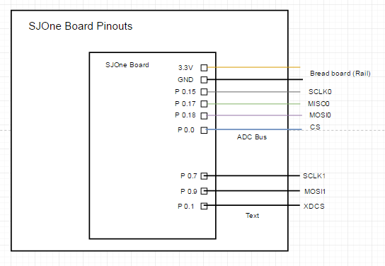
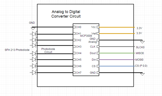
The pin layout utilizes both the SSP0 and SSP1 bus. The reasoning behind this design is to prevent bus contention between the MIDI board and the MCP3008. Although bus contention is an easy problem to prevent by coding the CS properly, both the MIDI and ADC tasks were programmed independently. It also made wiring easier for the layout since both the MIDI board and ADC wont share the same MISO, MOSI and SCLK wires.
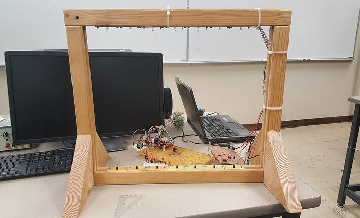
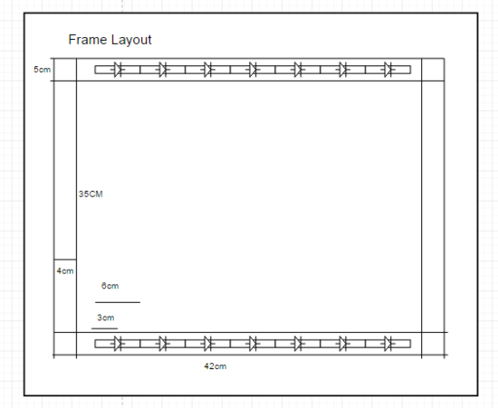
The distance between the photodiode and 850nm diode should be considered when building the frame. Both diodes picked for this project operate in a narrow range, but it was found later that the IR diode does have a wider range than expected.
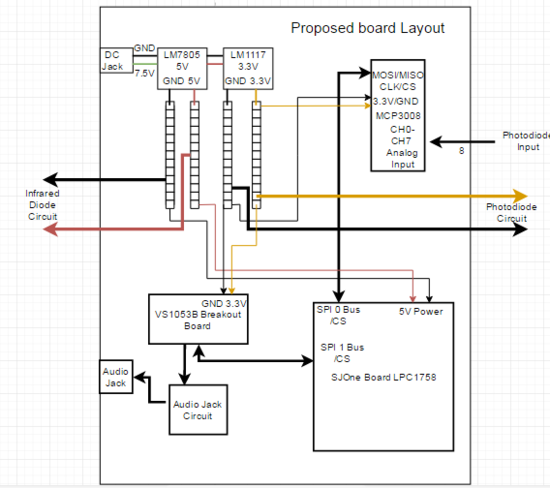
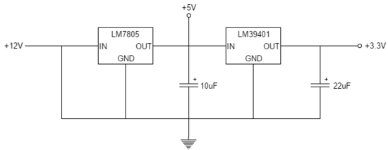
The power circuit is driven by a 12V adapter that is input to a 5V regulator. The 5V goes to a rail that powers the IR emitters. 3.3V powers the MIDI decoder and the photodiodes.
The VS1053b breakout board is an audio decoder that has hundreds of different instruments and can play musical notes. It is connected to the SJ One Board with the above pin connections and receives input via SPI for serial data interface, which is activated by XDCS chip select. To enable real-time MIDI, GPIO pin 0 must low, and GPIO pin 1 must be high. Unused GPIO pins need to have a pull down resistor and the RX pin needs to be tied to high as UART is not being used.
Hardware Interface
Communication is done with SPI protocol. Since the SJ One board has two SPI modules, SSP0 was used for ADC communication, and SSP1 was used for MIDI communication. GPIO was used for control signals such as such as chip selects and switches.
For the SPI drivers, both SSP0 and SSP1 controllers were initialized with the same parameters. It is set for 8-bit data transfer and 6MHz clock. To transfer data, there is a function to write one byte to the SPI data register.
We don't have a dedicated GPIO driver so each pin is initialized as GPIO and either input or output. Chip selects are set as outputs, with functions to clear and set bits. The push buttons are set as input and checked for when they are high to tell the board that an action must be taken. The chip selects for the MIDI and the ADC are toggled before and after each transaction.
For ADC Communication over the SPI0 bus, seven photodiode circuits are wired to channels 1-7 on the MCP3008. The photodiode circuit produces a varying analog voltage that will be converted to a digital value. In order to calibrate whether the beam is cut, Freertos is used to display and record the digital value while the IR diode is activating the photodiode, and when the beam to the photodiode is cut. We found that the digital value is lower when the beam the cut. Logically the program has to use an statement that works as follows: if (ch_n < 850) qSendToMidi(). That will activate the midi task to play the note.
For the IR diode, we sourced 5V from a LM7805. The motivation for the 5V was to ensure that the IR diodes emit the necessary radiation to create a noticeable change in the photodiode. For the photodiode, we were only able to get a stable voltage from the SJOne board.
Software Design
There are two tasks: the MIDI Task(consumer) and the ADC Task (producer). Data is sent between modules over SPI and the value in which a sensor has been triggered is stored in a FreeRTOS queue. The consumer task sleeps while waiting for the queue to receive a value.
The MIDI Task is high priority and handles sending commands to the VS1053 to turn a note on. When a note is received in the queue, the task wakes and processes the note type. Communication is done with the SJ One Board through SSP1.
The ADC Task is medium priority handles reading values from the sensors through the ADC converter by looping through every channel and checking if the value is above 835. If it is, it sends a corresponding note type to the queue, which signals the MIDI to play a note. This task also includes the volume and instrument controls, because the MIDI Task may be asleep when the button is pressed. Communication is done with the SJ One Board through SSP0.
Implementation
MIDI Task Algorithm
1. Sleep while queue is empty.
2. When a note is received, a message is sent to MIDI to turn note on.
3. Return to sleep.
4. Repeat.
ADC Task Algorithm
1. Read 'change volume/instrument' push buttons.
2. If active, perform relevant functions.
3. Read ADC channels 0-7 via SPI.
4. If data is below a certain value for channels 1-7, the note to be played is sent to the queue.
5. A message is sent to MIDI when the data returns to default to turn the note off.
6. Repeat.
Testing & Technical Challenges
The sensor to ADC communication and MIDI to SJ One Board communication were tested separately before bringing the parts together and adding the power supply. The ADC and MIDI tasks were first written to test their corresponding circuits, then the queue and GPIO buttons were added.
When building the ADC-Sensor circuit, it was difficult to line up the IR diode and photodiode to get a correct reading throughout the whole range. The range of the frame was tested at the farthest point successfully at first with one pair of sensors, however after everything was placed, some of the sensors didn't register towards the top of the frame.
The VS1053b breakout board took a little extra time because the datasheet lacks some information, especially regarding sending commands through SPI. Some commands only require one data byte following, and others require two. The data bytes that follow are the parameters that need to be set for each command, however not all commands are specified. There is also a need to add byte padding between each SPI transfer. Most of this information was found through research and some inferring.
Once the tasks were brought together and the frame was built, it became fairly simple since everything had already tested fairly successfully. There were still three diodes that only registered about three-quarters of the way. From here, additional features such volume and instrument control were added and tested. Minor improvements to the code were also made, one of them being setting a bool to hold a false value before every channel read to lower the chance of unwanted signals.
We would recommend having a clearer vision as to the physical layout of the frame and spending more time on creating a PCB. We wanted something that was similar to the feel of a harp, however it got pretty messy with all the wiring to 14 sensors and didn't end up very aesthetic. With a PCB, you can ensure that voltages will be more stable because we did come across some issues with voltages dropping.
My Issue #1
There was an issue with sending the note off command in the MIDI task because our queue only accounted for the note to be played, therefore some instruments would play the note forever. What we wanted to do was to have the note play as long as the sensor was blocked (indicated by bool variable in the ADC task), but we couldn't properly access the bool variable from the MIDI task. Therefore we have the note turn off in the ADC Task when the sensor is no longer blocked.
My Issue #2
When starting to wire the whole system on the prototype board, the 3.3V rail was unstable and was noticeable during SPI transactions. The cause might be because the voltage regulator chosen has noise or voltage drops, or the soldering was not done properly. The drops were not visible using a multimeter. Instead, the SJ One Board 3.3V source was tied to the breadboard and the photodiode circuits are connected to the rail.
Conclusion
Overall the basic features of the project were completed. We had some issues with unstable voltages and sensor calibration that set us back in schedule. Looking back, we also should have fixed our code to be more fluid and keep MIDI functions and ADC functions separate. This project allowed us to expand and enforce our knowledge on FreeRTOS and LPC1758 serial communication. We also learned how to use a MIDI decoder. If we were to add to the project, we would add LEDs to light up with activated sensors and implement a way to play multiple sounds at the same time.
Project Video
https://www.youtube.com/watch?v=ybSV1dKQTBQ
Project Source Code
References
Acknowledgement
Any acknowledgement that you may wish to provide can be included here.
References Used
VS1053b Breakout Board Datasheet, [1]
SFH4550 Infrared Emitter Datasheet, [2]
SFH213FA Silicon Photodiode, [3]
MCP3008 8-Channel 10-Bit ADC [4]
MIDI Commands, [5]
Appendix
You can list the references you used.
