Difference between revisions of "F21: Juvenile Jumpers"
Proj user6 (talk | contribs) (→Abstract) |
Proj user6 (talk | contribs) (→Testing & Technical Challenges) |
||
| Line 453: | Line 453: | ||
== Testing & Technical Challenges == | == Testing & Technical Challenges == | ||
| − | |||
| − | + | === PCB Design == | |
| + | We struggled to get the dimensions of the power supply module to design the PCB as the exact module was not available in the library. We have selected the pin dimensions for the power supply module by referencing other pin headers and using a general approximation to make it work satisfactorily. Because of this, the PCB went through a lot of internal revisions. While testing hardware on the PCB for the first time we faced a problem related to ribbon cable. | ||
=== Bug/issue and Solution === | === Bug/issue and Solution === | ||
Revision as of 00:48, 17 December 2021
Contents
Juvenile Jumpers
Abstract
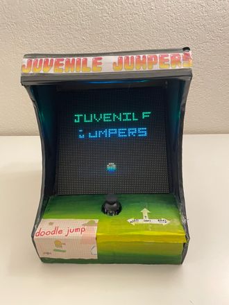
Juvenile Jumper is an endless platform game in which there are enemies and obstacles on various platforms. It is a single-player game. The doodle is a four-legged creature and has a trunk that he uses to shoot at enemies. The objective of the game is to go as high as you can without falling while avoiding/killing monsters and random obstacles. After each level, the difficulty of the game increases with more enemies and obstacles.
Objectives & Introduction
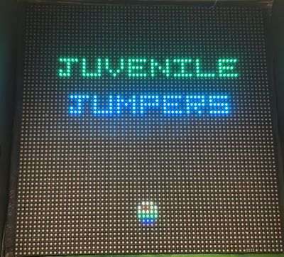
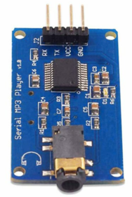
The idea is to build the doodle jump game on a 64x64 RGB LED Screen. The game is played using a joystick. The doodle keeps on jumping and its direction can be controlled using left and right control of the joystick, which can also be used in forward and backward direction as gun to shoot the monsters. MP3 decoder is used for different sound effects in the background of game.
Team Members & Responsibilities
Ritika Beniwal
- MP3 decoder driver
- Game Logic
- PCB design verification
- WiKi page handling
Anuja Sapkal
- Joystick driver
- Game Logic
- PCB Schematic and Board Design
- WiKi page handling
Sourab Gupta
- LED driver
- Game Logic
- PCB design verification
- WiKi page handling
Schedule
| Week# | Start Date | End Date | Task | Status |
|---|---|---|---|---|
| 1 |
|
|
|
|
| 2 |
|
|
|
|
| 3 |
|
|
|
|
| 4 |
|
|
|
|
| 5 |
|
|
|
|
| 6 |
|
|
|
|
| 7 |
|
|
|
|
| 8 |
|
|
|
|
| 8 |
|
|
|
|
| 9 |
|
|
|
|
Parts List and Cost
| Item# | Part Name | Part Supplier | Quantity | Cost |
|---|---|---|---|---|
| 1 |
64x64 RGB LED Matrix |
1 |
$ 87.4 | |
| 2 |
Sjtwo board |
1 |
$ 50 | |
| 3 |
Two-axis Joystick |
1 |
$ 4.25 | |
| 4 |
MP3 Decoder |
1 |
$ 8.05 | |
| 5 |
Power Supply |
1 |
$ 7.99 | |
| 6 |
PCB |
5 |
$14.21 |
Design & Implementation
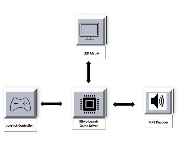
Juvenile Jumpers game is designed using SJ-Two board and RGB LED Matrix to see the visuals. The game is controlled by using a two-axis joystick and to play the music we have used an MP3 decoder.
Hardware Design
PCB Design
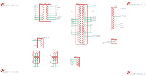
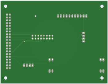
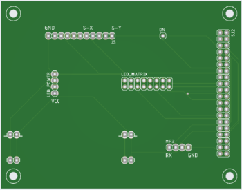
All the essential hardware is retained using a printed circuit board. For this game, we have designed a two-layer PCB. The schematic and board layout for the PCB is designed using Autodesk's Eagle software and the fabrication vendor is JLCPCB.
LED MATRIX
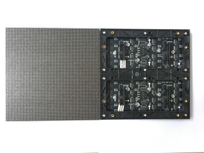
A 64x64 RGB LED Matrix is used as a display. The LED matrix panel has 4096 RGB LEDs. Each LED can be controlled independently. LED Matrix uses only 13 digital GPIOs to fully control each LED. This 64x64 LED matrix has six 64-bit shift registers for R1, G1, B1 R2, G2, B2 where each color of the LED is controlled by one bit of the shift register. The LED matrix displays three main colors like RED, BLUE, GREEN. By combing these three colors we can make different colors like YELLOW, CYAN, PINK, WHITE, Magenta.
| LED Matrix Pin | Pin Description | SJTwo Board Pin |
|---|---|---|
| R1 | Upper half (Section 1) | p2_0 |
| G1 | Upper half (Section 1) | p2_1 |
| B1 | Upper half (Section 1) | p2_2 |
| R2 | Lower half (Section 2) | p2_4 |
| G2 | Lower half (Section 2) | p2_5 |
| B2 | Lower half (Section 2) | p2_6 |
| A | Address Line | p2_7 |
| B | Address Line | p2_8 |
| C | Address Line | p2_9 |
| D | Address Line | p0_16 |
| E | Address Line | p0_15 |
| GND | Connected to ground | GND |
| Clk | For upper half and lower half | p1_28 |
| Latch | For upper half and lower half | p1_23 |
| OE | For upper half and lower half | p1_20 |
Dual Axis Joystick
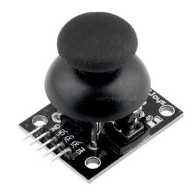
This project uses the joystick to control the movements of the jumper. This project uses x-axis values to move the jumper to the left and right sides. A switch on the joystick is used to start the game by pressing the switch. The joystick provides the analog output, therefore the joystick is connected to ADC pins of the SJTwo board. It is operated on a 5V power supply.
MP3 Decoder
Hardware Interface
Software Design
This game has two levels.
1. Level_1:
- In the first level, the player needs to jump on the tiles. Some tiles have spring on them, therefore if the jumper collides with spring tiles score will increase by two times.
- If the score is more than 160 then the second level will begin.
2. Level_2:
- This level adds some difficulty to the game. This level has enemies.
- Jumper has a gun functionality. By using a gun jumper can kill the enemy.
- If the jumper collides with the enemy game will be over.
There is a total of five tasks involved in this game in order to ensure full functionality.
1. Start and stop task:
- This task displays the game's start screen. To start the game player need to press the onboard switch on the joystick.
- When the game is over this task display game over screen.
2. Background task:
- This task creates background tiles
- It keeps replacing the frame buffer with background data.
3. Game logic task:
- When the game starts this task detects the jumper's initial position and starts jumping up.
- Jumper will start going down after reaching a certain height.
- It checks for the collision with tiles. If a collision is not detected then the jumper will keep going down.
- If a collision is detected then it shifts the background screen and jumpers down.
- It will update the score and check the level.
- If the score is more than 160, it will start level 2 of the game.
4 LED tasks:
- This task keeps displaying frame data every 1ms.
- This is a high-priority task.
5 Enemy tasks:
- This task creates enemies at a random position.
- It moves enemies from column 0 to 63.
Implementation
LED Driver
LED matrix will initialize by configuring the required pin directions. Before feeding matrix data disable Output Enable (OE) GPIO. Set bits on A, B, C, D GPIO pins to select the particular row. Loop through the pixels (columns) in the selected row and set the pixel color on R, G, B GPIO pins. To mask that particular pixel set zero on R, G, B GPIO pins. Set and Reset the clock for pushing the R, G, B bits for each column. Issue latch to mark the row's completion and reset latch before going to next row.
Code snippet for LED Driver:
void led_matrix__set_pixel(int row, int column, led_matrix__color_e color) {
  // column = 63 - column;
  data_size pixel = ((data_size)1 << column);
  if (color & BLUE_COLOR_BIT) {
    frame_buffer[row][BLUE_PLANE] |= pixel;
  }
  if (color & GREEN_COLOR_BIT) {
    frame_buffer[row][GREEN_PLANE] |= pixel;
  }
  if (color & RED_COLOR_BIT) {
    frame_buffer[row][RED_PLANE] |= pixel;
  }
  if (color == OFF) {
    clear_pixel(row, column);
  }
}
MP3 Decoder
- mp3 music changes according to the state of the game.
- To get the game state sound flags are checked.
- Music is placed in the file so need to find the respective file.
- Open the mp3 file.
- Read the contents of the file.
Code snippet for MP3:
void mp3_play_sound(int num) { mp3__send_command(PLAY_FILE_WITH_FOLDER, 0x01, num); }

void mp3_play_jump_up_sound() {
  mp3_play_sound(2);
  vTaskDelay(50);
}
Joystick
- Initialized the ADC Peripheral
- Set the appropriate pin functionality using the IOCON registers.
- Set the ADC pin functionality as input.
- Select ADC channels to read.
- Enable burst mode for a fast conversion.
Code snippet for Joystick:
void initialize_joystick() {
  enable_joystick(GPIO__PORT_0, 25, GPIO__PORT_1, 30, GPIO__PORT_1, 31);
  button_press = p1;
}
Testing & Technical Challenges
= PCB Design
We struggled to get the dimensions of the power supply module to design the PCB as the exact module was not available in the library. We have selected the pin dimensions for the power supply module by referencing other pin headers and using a general approximation to make it work satisfactorily. Because of this, the PCB went through a lot of internal revisions. While testing hardware on the PCB for the first time we faced a problem related to ribbon cable.
Bug/issue and Solution
1. Collision detection with tiles not working after the 32nd column. This is due to the variable was not typed cast to uint64_t.
2. The random number generator generates the same pattern and hence the tiles. Seeding just once with xTaskGetTickCount() did not generate randomness.
3. Led buffer overwrite due to collision leaves background screen in an inconsistent state. To resolve this issue keep refreshing the background screen in a task.
Conclusion
We successfully designed the Juvenile Jumper game using the RGB LED Matrix and the SJ2 board. Implementing this project from scratch gave us more practical exposure in developing real-time embedded applications. This project helped us have a better understanding of the FreeRTOS scheduler tasks.
Project Video
Project Source Code
References
Acknowledgement
We would like to sincerely thank Professor Preetpal Kang for designing such a fantastic course and for his continuous guidance and support throughout the implementation of this project. Further, we would like to thank the ISA team for their advice.
