Difference between revisions of "S23: CAN CLAN"
(→Communication Bridge Controller & LCD) |
(→Printed Circuit Board) |
||
| Line 381: | Line 381: | ||
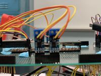
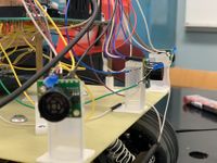
This is the picture shows protoboard. | This is the picture shows protoboard. | ||
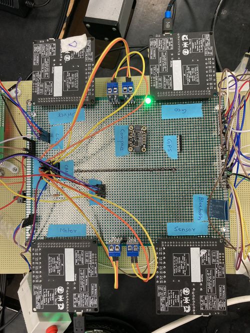
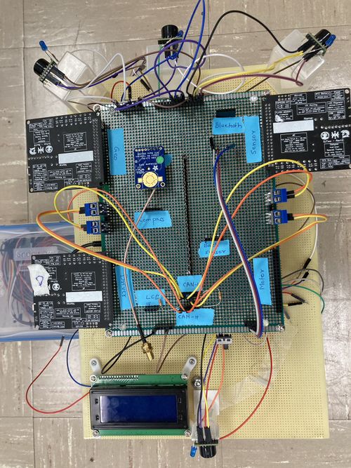
| − | [[File:Printed_Circuit_Board1.jpg|500px|Image: 250 pixels]] | + | [[File:Printed_Circuit_Board1.jpg|500px|Image: 250 pixels]][[File:Printed_Circuit_Board2.jpg|500px|Image: 250 pixels]] |
<HR> | <HR> | ||
Revision as of 00:05, 14 May 2023
Contents
CAN CLAN
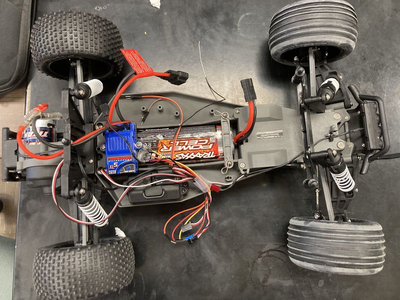
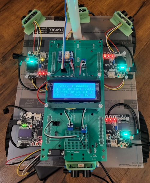
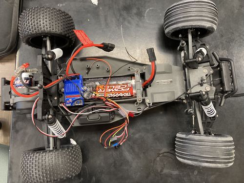
Picture of the RC Car
Abstract
Our goal for this project is to use knowledge we gathered from lectures to design, implement, and test a self-driving RC car using a Controller Area Network (CAN) bus for controller communication. The project involves FreeRTOS and utilizes periodic tasks (running at 1Hz, 10Hz, and 100Hz) to gather, process, and display data from various embedded modules.
Introduction
The project was divided into 5 modules:
- Sensor Information
- Motor Operation
- Geological Information
- Driver & LCD Manager
- Bridge & Android Application
Team Members & Responsibilities
<Team Picture>
Gitlab Project Link - https://gitlab.com/rashmi_sv/the_CAN_clan.git
Rashmi Suhas Vaidya
- Geo Controller
- GPS and Compass Interfacing
- Driver Node
- Integration Testing

Zeel Jatinkumar Lia
- Sensor and Bridge Controller
- RPM Sensor
- Driver Node
- Integration Testing

Priyam Hajisheth
- Driver Node
- LCD interfacing
- Mobile App
- Integration Testing

Xinyu He
- Hardware solution
- Wiki Page Update
- Integration Testing

Hongjin Cheng
- RPM Sensor
- Motor Controller
- Hardware assembling
- Integration Testing
Schedule
| Week# | Start Date | End Date | Task | Status |
|---|---|---|---|---|
| 1 | 03/01/2023 | 03/07/2023 |
|
|
| 2 | 03/08/2023 | 03/14/2023 |
|
|
| 3 | 03/15/2023 | 03/21/2023 |
|
|
| 4 | 03/22/2023 | 03/28/2023 |
|
|
| 5 | 03/29/2023 | 04/04/2023 |
|
|
| 6 | 04/05/2023 | 04/11/2023 |
|
|
| 7 | 04/12/2022 | 04/18/2022 |
|
|
| 8 | 04/19/2023 | 04/25/2023 |
|
|
| 9 | 04/26/2023 | 05/02/2023 |
|
|
| 10 | 05/03/2023 | 05/09/2023 |
|
|
| 11 | 05/10/2023 | 05/16/2023 |
|
|
| 11 | 05/23/2023 | 05/23/2023 |
|
|
Parts List & Cost
| Item# | Part Desciption | Vendor | Qty | Cost |
|---|---|---|---|---|
| 1 | RC Car | Traxxas [1] | 1 | $251.51 |
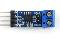
| 2 | CAN Transceivers | Amazon [2] | 4 | $43.72 |
| 3 | SJ-2 Board | 4 | $200.00 | |
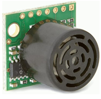
| 4 | LV-MaxSonar-EZ1 Ultrasonic Range Finder | Amazon [3] | 4 | $131.20 |
| 5 | GPS | Amazon [4] | 1 | $10.99 |
| 6 | RPM Sensor | Amazon [5] | 1 | $16.76 |
| 7 | Buletooth | Amazon[6] | 1 | $15.99 |
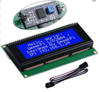
| 8 | LCD Display | Amazon [7] | 1 | $10.99 |
| 9 | Battery/Charger | 1 | $62.95 | |
| 10 | Cable | Amazon [8] | 1 | $7.99 |
| 11 | LSM303AGR Compass | Adafruit [9] | 1 | $19.57 |
| 12 | Magnet holder | 1 | $8.09 | |
| 13 | 2*20 header | 1 | $7.59 | |
| 14 | RPM holder | 1 | $7.73 | |
| 15 | long stand off | 1 | $2.21 | |
| 16 | Mount board | 1 | None | |
| 17 | Protoboard | 1 | None | |
| 18 | Small stand off | None | ||
| 19 | Pin header | None | ||
| 20 | Switch for DC motor | 1 | None | |
| 21 | wire connectors | 1 | None |
Printed Circuit Board
The Following table indicate the pin connection of all Hardware .
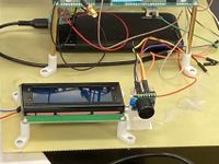
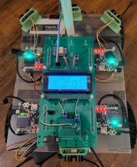
This is the picture shows protoboard.
CAN Communication
<Talk about your message IDs or communication strategy, such as periodic transmission, MIA management etc.>
Hardware Design
<Show your CAN bus hardware design>
DBC File
Gitlab link to our DBC file : https://gitlab.com/rashmi_sv/the_CAN_clan/-/blob/dev/dbc_file/dbc/project.dbc
<You can optionally use an inline image>
VERSION ""

NS_ :
        BA_
        BA_DEF_
        BA_DEF_DEF_
        BA_DEF_DEF_REL_
        BA_DEF_REL_
        BA_DEF_SGTYPE_
        BA_REL_
        BA_SGTYPE_
        BO_TX_BU_
        BU_BO_REL_
        BU_EV_REL_
        BU_SG_REL_
        CAT_
        CAT_DEF_
        CM_
        ENVVAR_DATA_
        EV_DATA_
        FILTER
        NS_DESC_
        SGTYPE_
        SGTYPE_VAL_
        SG_MUL_VAL_
        SIGTYPE_VALTYPE_
        SIG_GROUP_
        SIG_TYPE_REF_
        SIG_VALTYPE_
        VAL_
        VAL_TABLE_

BS_:

BU_: DBG DRIVER GEO MOTOR SENSOR_BRIDGE


BO_ 100 ULTRASONIC_TO_DRIVER: 5 SENSOR_BRIDGE
 SG_ ULTRASONIC_TO_DRIVER_left : 0|10@1+ (1,0) [0|511] "cm" DRIVER
 SG_ ULTRASONIC_TO_DRIVER_right : 10|10@1+ (1,0) [0|511] "cm" DRIVER
 SG_ ULTRASONIC_TO_DRIVER_front : 20|10@1+ (1,0) [0|511] "cm" DRIVER
 SG_ ULTRASONIC_TO_DRIVER_back : 30|10@1+ (1,0) [0|511] "cm" DRIVER

BO_ 300 GPS_DESTINATION: 8 SENSOR_BRIDGE
 SG_ GPS_DEST_LATITUDE_SCALED_100000 : 0|32@1- (1,0) [0|0] "Degrees" GEO
 SG_ GPS_DEST_LONGITUDE_SCALED_100000 : 32|32@1- (1,0) [0|0] "Degrees" GEO

BO_ 50 DRIVE_STATUS_CMD: 1 SENSOR_BRIDGE
 SG_ DRIVE_STATUS_CMD_start : 0|1@1+ (1,0) [0|0] "" MOTOR

BO_ 600 SELF_TEST_CMD: 1 SENSOR_BRIDGE
 SG_ SELF_TEST_CMD_start : 0|1@1+ (1,0) [0|0] "" MOTOR, GEO, DRIVER


BO_ 200 DRIVER_TO_MOTOR: 2 DRIVER
 SG_ DRIVER_TO_MOTOR_steer : 0|8@1- (1,0) [0|0] "degrees" MOTOR, SENSOR_BRIDGE
 SG_ DRIVER_TO_MOTOR_speed : 8|8@1- (1,0) [0|50] "mph" MOTOR, SENSOR_BRIDGE

BO_ 610 DRIVER_SELF_TEST_RESULT: 1 DRIVER
 SG_ DRIVER_SELF_TEST_RESULT_status : 0|8@1+ (1,0) [0|0] "" SENSOR_BRIDGE


BO_ 400 GEO_STATUS: 8 GEO
  SG_ GEO_STATUS_COMPASS_HEADING : 0|12@1+ (1,0) [0|359] "Degrees" DRIVER, SENSOR_BRIDGE
  SG_ GEO_STATUS_COMPASS_BEARING : 12|12@1+ (1,0) [0|359] "Degrees" DRIVER, SENSOR_BRIDGE
  SG_ GEO_STATUS_DISTANCE_TO_DESTINATION : 24|16@1+ (0.1,0) [0|0] "Meters" DRIVER, SENSOR_BRIDGE
  SG_ GEO_STATUS_SATELLITE_LOCKED : 40|1@1+ (1,0) [0|0] "" DRIVER, SENSOR_BRIDGE

BO_ 620 GEO_SELF_TEST_RESULT: 1 GEO
 SG_ GEO_SELF_TEST_RESULT_status : 0|8@1+ (1,0) [0|0] "" SENSOR_BRIDGE

BO_ 650 GEO_CURRENT_COORDS: 8 SENSOR_BRIDGE
 SG_ CURR_LATITUDE_SCALED_100000 : 0|32@1- (1,0) [0|0] "Degrees" SENSOR_BRIDGE
 SG_ CURR_LONGITUDE_SCALED_100000 : 32|32@1- (1,0) [0|0] "Degrees" SENSOR_BRIDGE


BO_ 500 MOTOR_TO_APP_DBG: 2 MOTOR
 SG_ MOTOR_TO_APP_DBG_current_steer : 0|8@1- (1,0) [0|0] "degrees" SENSOR_BRIDGE
 SG_ MOTOR_TO_APP_DBG_current_speed : 8|8@1- (1,0) [0|50] "mph" SENSOR_BRIDGE

BO_ 620 MOTOR_SELF_TEST_RESULT: 1 MOTOR
 SG_ MOTOR_SELF_TEST_RESULT_status : 0|8@1+ (1,0) [0|0] "" SENSOR_BRIDGE


CM_ BU_ DRIVER "The LED display and driver controller driving the car";
CM_ BU_ MOTOR "The RPM sensor, DC and servo motor controller of the car";
CM_ BU_ SENSOR_BRIDGE "The Bluetooth and the sonar sensor controller of the car";
CM_ BU_ GEO "The GPS and compass sensor controller of the car";

BA_DEF_ "BusType" STRING ;
BA_DEF_ BO_ "GenMsgCycleTime" INT 0 0;
BA_DEF_ SG_ "FieldType" STRING ;

BA_DEF_DEF_ "BusType" "CAN";
BA_DEF_DEF_ "FieldType" "";
BA_DEF_DEF_ "GenMsgCycleTime" 0;

BA_ "GenMsgCycleTime" BO_ 100 1000;
BA_ "GenMsgCycleTime" BO_ 200 50;
Sensor ECU
<Picture and link to Gitlab> Sensor Node GitLab
Hardware Design
- MaxSonar-EZ1 detects objects from 0" to 254".
- 2.5-5.5V operation range. Low 2mA supply current.
- 42kHz Ultrasonic sensor with 20Hz reading rate.
- Incredibly Small Package Sonar Range Finder.
- Serial Output, PWM output, Analog Output.
Software Design
<List the code modules that are being called periodically.>
Technical Challenges
< List of problems and their detailed resolutions>
- Issue: Sensors test well independently, but not sensitive when mount on RC car .
- Reason: Sensor do not have enough power supply.
- Solution: 1.check connecting and solder in protoboard.
- 2.Re-design the power supply plan.
- Issue: While using two brand sensors, Front sensor works well, but left/right sensor working randomly. For sensors couldn’t work well at the same time.
- Reason: We config the sensor in two groups, and it causes the sensors to crosstalk.
- Solution: 1. Only use one brand.
- 2.Turning on only two sensors at a time.(left + right then front +rear).
- Issue: Rear Sensor doesn't work well with bad mounting.
- Reason: the sensors are mounted heading to LCD.
- Solution: we use higher stand off of read sensor.
Motor ECU
<Picture and link to Gitlab> Motor Controller Link
Hardware Design
A single SJ2-C board was placed in charge of handling all interactions with the Traxxas parts. This included an ESC (Electronic Speed Control) connected to a brushed DC motor, a servo motor for steering control, and a wheel encoder installed adjacent to the gear shaft (CHECK).
Software Design
<List the code modules that are being called periodically.>
Technical Challenges
< List of problems and their detailed resolutions>
Geographical Controller
<Picture and link to Gitlab> GPS Node GitLab
- GPS
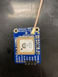
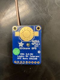
- An Adafruit Ultimate GPS breakout module using the MTK3339 chipset is interfaced over UART to the Geographical controller to provide latitude and longitude updates.
- Compass
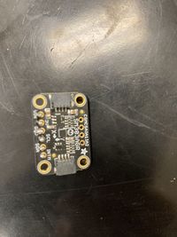
- Triple-axis accelerometer/magnetometer compass module. Inside are two sensors, one is a classic 3-axis accelerometer, which can tell you which direction is down towards the Earth (by measuring gravity). The other is a magnetometer that can sense where the strongest magnetic force is coming from, generally used to detect magnetic north.
Hardware Design
Software Design
<List the code modules that are being called periodically.>
Technical Challenges
< List of problems and their detailed resolutions>
Communication Bridge Controller & LCD
<Picture and link to Gitlab>
- LCD
- An Adafruit Ultimate GPS breakout module using the MTK3339 chipset is interfaced over UART to the Geographical controller to provide latitude and longitude updates.
Hardware Design
Software Design
<List the code modules that are being called periodically.>
Technical Challenges
< List of problems and their detailed resolutions>
Master Module
<Picture and link to Gitlab>
Hardware Design
Software Design
<List the code modules that are being called periodically.>
Technical Challenges
< List of problems and their detailed resolutions>
Mobile Application
<Picture and link to Gitlab>
Hardware Design
Software Design
<List the code modules that are being called periodically.>
Technical Challenges
< List of problems and their detailed resolutions>
Conclusion
<Organized summary of the project>
<What did you learn?>
Project Video
Project Source Code
Advise for Future Students
<Bullet points and discussion>
Acknowledgement
=== References ===
