S16: Fantastic Four
Contents
Smart Alarm Clock for the Stubborn Sleeper
Abstract
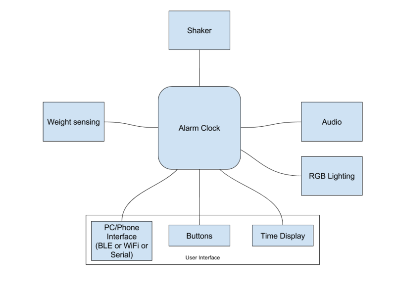
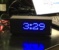
This smart alarm clock encapsulates a variety of features that are intended to wake up a stubborn sleeper who cannot get up in the morning. As opposed to your average alarm clock, this alarm clock has the ability to wake up the user using dynamic lighting combined with customizable sounds. An external unit, which is placed beneath the mattress, has a bass shaker built in to vibrate the mattress to aid in helping the user get out of bed. The external mattress unit also has a flex sensor that can detect whether the user is in bed or not, and is used to turn off the alarm once the user gets out of bed.
Objectives & Introduction
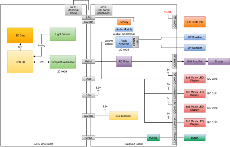
The alarm is made up of two modules, one being the alarm clock unit and an external mattress unit which is placed underneath the user's mattress. The heart of the main alarm unit starts with the SJOneBoard (LPC1758) microcontroller. From there, we branch out to the following peripherals:
- Nordic wireless communication with the external mattress unit
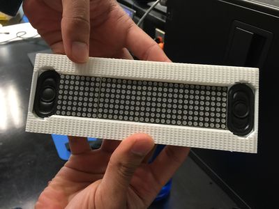
- Four 8X8 blue LED matrix displays (HT16K33) with RAM mapping controller drivers interfaced over I2C
- Audio module (VS1053 Codec) with two 2W 8 OHM speakers interfaced using a Teensy Development Board which is communicating with the SJOneBoard over UART.
- RGB LED strips (144 LEDs/m) interfaced over SPI
- A capacitive snooze button interfaced over GPIO
The external mattress unit is driven by another SJOneBoard (LPC1758) microcontroller which drives the following peripherals:
- Nordic wireless communication with the main alarm unit
- Bass Shaker with a 50W amplifier interfaced over PWM
- Flex sensor interfaced using ADC
Show list of your objectives. This section includes the high level details of your project. You can write about the various sensors or peripherals you used to get your project completed.
Team Members & Responsibilities
- Sara Sepasian
- RGB LEDs
- Michael Jaradah
- Breakout board schematic capture and layout, RGB LEDs, network, shaker, force sensor
- Rabeel Elahi
- 8X8 LED Matrix Displays, overall software implementation, wireless mesh network
- Farhan Naeem
- Hardware architecture, board layout, software architecture, mechanical design and integration, audio module
Schedule
| Week# | Date | Task | Status | Notes | |
|---|---|---|---|---|---|
| 1 | 3/22 | Hardware architecture
|
Completed |
|
|
| 1 | 3/27 | Software architecture
|
Completed | ||
| 2 | 3/29 | Schematic capture, BOM & design review
|
Completed | ||
| 2 | 3/30 | Order components | Completed | ||
| 3 | 4/5 | Board layout & design review
|
Completed | ||
| 3 | 4/7 | Order PCB | Completed | ||
| 6 | 5/1 | Receive, assemble and test board | Completed | ||
| 6 | 5/1 | Software module development
|
Completed | ||
| 7 | 5/7 | Software integration
|
Completed | ||
| 8 | 5/15 | Debug and test | Completed |
Parts List & Cost
VS1053 Codec + MicroSD Breakout x1 (~$25)
8x8 matrix displays x4 (~$13)
Stereo 2.8W Class D Audio Amplifier x1 (~$10)
2W 8OHM OVL SHP SPKR x2 (~$6)
50W Amplifier x1 (~$15)
Bass shaker x1 (~$21)
Flex Sensor x1 (~$8)
PCB x1 ($40)
Custom Made Enclosure
Design & Implementation
Hardware Design
Hardware Architecture
Breakout Board Schematic
Breakout Board PCB
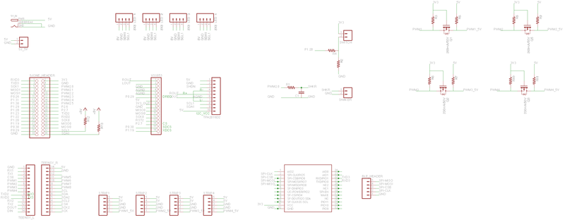
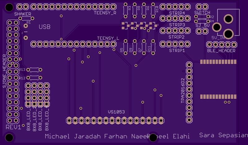
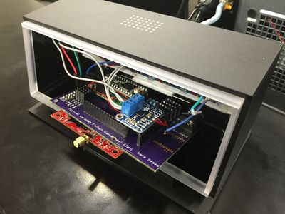
Our alarm clock contained many different components that needed to be wired together. In order to keep things packaged and wired efficiently, we decided to create a custom PCB that would fit directly on top of the SJOne board, and act as a breakout board.
To design our custom PCB board, we used Eagle version 7.5.0, which is a free tool available for download online. The application allows users to create their own PCB's for free up to a certain dimension, so we made sure to keep our board within the free space allowed. Before starting the PCB work, we made sure to download all additional libraries from outside sources such as Sparkfun and Adafruit, to avoid using hard-to-find components. Their libraries have been tested and used by many PCB's before, so we went ahead with theirs and avoided others.
The bulk of our breakout board was filled with headers, which allowed different devices such as: an amplifier, audio decoder, LED matrix displays, SPI LED strips, a Teensy Header, and the SJOne board. In addition to housing these components, the board contained a level shifter for the LED's. an RC filter designed for a transducer shaker, a power jack, a power supply for the SJOne board, a header for a capacitive switch, as well as a BLE pad and BLE Programmer header. In order to minimize noise, a power copper layer as well as a ground copper layer were added to the top and back of the board. This cleaned up the wiring a lot, since every component contained these wires.
After the schematic and board files were completed, we went with a US-based PCB fab company called OshPark. This company is known for their purple PCB's, being very reliable, and having quick turn around time. In addition to this, their website is very user friendly and designed to be for hobbyist. They do not require any gerber files, and generate every file they need by uploading the .sch and .brd files. From there, they automatically generate the files and go through the design checking process. In total, the PCB took 11 days from submission of payment to receiving the board.
8X8 LED Matrix Displays
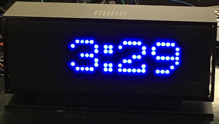
The 8x8 matrix displays with backpack drivers (HTK1633) were chosen primarily because of their ultra-bright pixels which shine through the black fabric mesh on the front of the alarm clock. These specific displays are interfaced over I2C, making the wiring less hectic since I2C uses only two wires (SDA and SCL). External pull-up resistors were not needed since the backpack drivers had them built in. Each display requires 5V at 1.5 mA which is sourced by the breakout board's +5V supply. The SJOneBoard (master) drives the addressable displays with SCL running at the specified frequency of 400 kHz.
Industrial Design
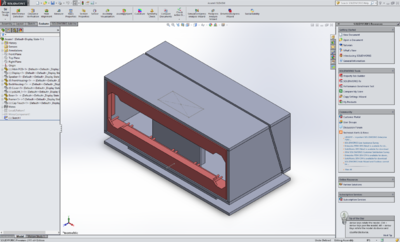
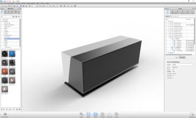
We collaborated with an industrial designer to design a custom mechanical package that houses all of the electrical components.
Hardware Assembly/Integration
Hardware Interface
Refer to the Hardware Architecture diagram above for an overview of the interfaces utilized.
Software Design
Implementation
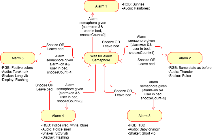
Alarm Clock Task / State Machine
class alarmTask : public scheduler_task
{
public:

	alarmTask(uint8_t priority) : scheduler_task("alarmTask", 2048, priority), state(WAIT_FOR_ALARM){

	}

	bool init(void)
	{
		audioObj.initAudio();	            //initialize audio interface
		GPIO myPin(P2_6);                     //set GPIO for snooze button
		myPin.setAsInput();
		eint3_enable_port2(6, eint_rising_edge, button_interrupt);  //configure interrupt for snooze button
		alarmStates state = ALARM1;   //set state machine initial state

		return true;
	}

	bool run(void *p)
	{
                //alarm semaphore
		if (xSemaphoreTake(timeSem, portMAX_DELAY)){
                        //only activate alarm if it has been enabled by the user
			if(alarm_is_on)
			{
				switch(state){
				case ALARM1:
					if(user_in_bed){
						alarmObj.activateAlarmLevel1;
						state = ALARM2;
					}
					else{
						state = ALARM1;
					}
					break;
				case ALARM2:
					if(user_in_bed){
						alarmObj.activateAlarmLevel2;
						state = ALARM3;
					}
					else{
						state = ALARM1;
					}
					break;
				case ALARM3:
					if(user_in_bed){
						alarmObj.activateAlarmLevel3;
						state = ALARM4;
					}
					else{
						state = ALARM1;
					}
					break;
				case ALARM4:
					if(user_in_bed){
						alarmObj.activateAlarmLevel4;
						state = ALARM5;
					}
					else{
						state = ALARM1;
					}
					break;
				case ALARM5:
					if(user_out_of_bed){
						alarmObj.activateAlarmLevel5;
						state = ALARM1;  //user is out of bed, reset to alarm1 for the next time
					}
					else{
						state = ALARM5;  //repeat alarm until user gets out of bed
					}
					break;
				}
			}
		}
		vTaskDelay(1000);
		return true;
	}
private:
	SemaphoreHandle_t timeSem = xSemaphoreCreateBinary();  //semaphore for alarm
	alarm& alarmObj = alarm::getInstance();                                  //get instance of alarm object
	matrix& matrixObj = matrix::getInstance();                              //get instance of LED matrix display object
	shaker& shakerObj = shaker::getInstance();                            //get instance of shaker control object
	audio& audioObj = audio::getInstance();                                  //get instance of audio object

        //state machine states
	enum alarmStates {
		WAIT_FOR_ALARM,
		ALARM1,
		ALARM2,
		ALARM3,
		ALARM4,
		ALARM5
	};

	alarmStates state;

};
Matrix Display Class
The matrix class was created using the singleton template so that only one instance of the class could be used throughout the code structure. The class consisted of various helper functions that initialized, cleared, and wrote to the displays as seen below. The helper functions would fetch the instance of I2C1 and write to the display registers. Since the breakout board was connected to the SJOneBoard header pins, I2C1 had to be used versus I2C2 which is located under the two 7-segment displays. In order to do this, a separate class, which inherited I2C_base class, had to be created for I2C1.
        /**
	 *  Get instance of I2C1 class and initialize I2C1 to 400 kHz
	 */
	I2C1& i2c = I2C1::getInstance();
	i2c.init(400);

	/**
	 *  Get instance of matrix class
	 */
	matrix& matrix = matrix::getInstance();

	/**
	 *  Initialize displays:
         *
         *             matrix.init(display address, brightness, blink frequency)
	 */
	matrix.init(0xe2,0xEF,0x81); //Display 1
	matrix.init(0xe0,0xEF,0x81); //Display 2
	matrix.init(0xe8,0xEF,0x81); //Display 3
	matrix.init(0xe4,0xEF,0x81); //Display 4

        /**
	 *  Clears the displays
	 */
	matrix.clearDisplay(void);

	/**
	 *  Writes time to the displays and accounts for colon
	 *
	 *  @param string time to be written to display
	 */
	matrix.setTime(char string[]);

	/**
	 *  Writes any four letter word/number to the display
	 *
	 *  @param string string to be written to display
	 */
	matrix.writeDisplays(char string[]);
Testing & Technical Challenges
Describe the challenges of your project. What advise would you give yourself or someone else if your project can be started from scratch again? Make a smooth transition to testing section and described what it took to test your project.
Include sub-sections that list out a problem and solution, such as:
Difficulties interfacing with VS1053 audio module
Implemented driver as per manufacturer's recommendation. However we were unable to get it to work. Communications protocol was too complicated to fix/troubleshoot within planned time period. Resorted to using a Teensy board along with an audio module. A UART interface was implemented on the Teensy to read audio file selection sent from the SJ One board.
Clock frequency for RGB LEDs too high for MOSFET based level shifting circuit
The RGB LEDs initially selected for the project (WS2812) required a signal of 800kHz. The WS2812 requires 5V digital input, therefore requiring us to level shift the 3.3V output of the LPC microcontroller to 5V. The level shifting was implemented using a MOSFET based circuit with 3 pull-up resistors. The combination of the pullup resistors along with the internal capacitance of the MOSFET and the board capacitance resulted in the 800kHz signal being significantly attenuated. We ultimately resorted to switching to a different RGB LED strip which has less strict of a timing requirement as there's a separate clock signal in addition to the data signal. This allowed us to adjust the data rate by just setting the clock speed.
Conclusion
This project offered valuable experience in working on a complex product comprising of various subsystems with multiple developers working together simultaneously. We had to constantly communicate with one another to discuss interfaces and how each one of our subsystems will talk to each other. It also allowed us to gain further appreciation for FreeRTOS, by allowing us to split up our project into logical subsystems instead of having to put everything into one huge while loop as would've been done otherwise if it weren't for the RTOS. We got an opportunity to leverage most of the things we learned in class such as semaphores, queues and interrupts. By working on this project we also got an opportunity to utilize all the hardware interfaces (I2C, UART, SPI, Analog in, etc.) available on a typical microcontroller.
We also learned how challenging integrating hardware and software can be. At times we had pull out an oscilloscope to debug at the signal level to isolate whether an issue is due to hardware or software.
Project Source Code
References
Acknowledgement
Any acknowledgement that you may wish to provide can be included here.
References Used
List any references used in project.
Appendix
You can list the references you used.
