S19: CANT Bus
Contents
Grading Criteria
- How well is Software & Hardware Design described?
- How well can this report be used to reproduce this project?
- Code Quality
- Overall Report Quality:
- Software Block Diagrams
- Hardware Block Diagrams
- Schematic Quality
- Quality of technical challenges and solutions adopted.
Project Title
[C]ompile [A]nother [N]on-[T]rivial Bus
Abstract
<2-3 sentence abstract>
Introduction
The project was divided into N modules:
- Sensor ...
- Motor..
- ...
- Android
Team Members & Responsibilities
- Kevin Chan
- Lidar, Tachometer, Power, Wireless communications
- Khrysta Finch
- Assistant Team Leader, Chassis, Telemetry, Compass, Driver (PCB/Schematic)
- Andrew Javier
- Motor, Steering, Compass, Wireless communications (GPS, Lidar, Chasis)
- Aaron Lee
- GPS, Mobile App (Compass, Telemetry)
- Jonathan Rojas
- GPS, Lidar, Tachometer, Power
- Vijay Vanapalli
- Motor, Steering, PCB/Schematic (Mobile App)
- Nelson Wong
- Team Leader, Driver, Telemetry, PCB/Schematic, Chassis, Mobile App
<Team Picture>
Gitlab Project Link - [1]
<Provide ECU names and members responsible> <One member may participate in more than one ECU>
- Sensor
- Link to Gitlab user1
- Link to Gitlab user2
- Motor
- Link to Gitlab user1
- Link to Gitlab user2
- Geographical
- Link to Gitlab user1
- Link to Gitlab user2
- Communication Bridge Controller & LCD
- Link to Gitlab user1
- Link to Gitlab user2
- Android Application
- Link to Gitlab user1
- Link to Gitlab user2
- Testing Team
- Link to Gitlab user1
- Link to Gitlab user2
Schedule
Show a simple table or figures that show your scheduled as planned before you started working on the project. Then in another table column, write down the actual schedule so that readers can see the planned vs. actual goals. The point of the schedule is for readers to assess how to pace themselves if they are doing a similar project.
| Week# | Start Date | End Date | Task Description | Status | Completion Date |
|---|---|---|---|---|---|
| 1 | 3/4 | 3/10 |
|
Complete | |
| 2 | 3/11 | 3/17 |
|
||
| 3 | 3/18 | 3/24 |
|
||
| 4 | 3/25 | 3/31 |
|
||
| 5 | 4/1 | 4/7 |
|
||
| 6 | 4/8 | 4/14 |
|
||
| 7 | 4/15 | 4/21 |
|
||
| 8 | 4/22 | 4/28 |
|
||
| 9 | 4/29 | 5/5 |
|
||
| 10 | 5/6 | 5/12 |
|
Parts List & Cost
| Item# | Part Desciption | Vendor | Qty | Cost |
|---|---|---|---|---|
| 1 | RC Car | Traxxas | 1 | $250.00 |
| 2 | CAN Transceivers MCP2551-I/P | Microchip [2] | 8 | Free Samples |
Printed Circuit Board
<Picture and information, including links to your PCB>
CAN Communication
<Talk about your message IDs or communication strategy, such as periodic transmission, MIA management etc.>
Hardware Design
<Show your CAN bus hardware design>
CAN Communication
243.dbc
VERSION "1.0"

NS_ :
    BA_
    BA_DEF_
    BA_DEF_DEF_
    BA_DEF_DEF_REL_
    BA_DEF_REL_
    BA_DEF_SGTYPE_
    BA_REL_
    BA_SGTYPE_
    BO_TX_BU_
    BU_BO_REL_
    BU_EV_REL_
    BU_SG_REL_
    CAT_
    CAT_DEF_
    CM_
    ENVVAR_DATA_
    EV_DATA_
    FILTER
    NS_DESC_
    SGTYPE_
    SGTYPE_VAL_
    SG_MUL_VAL_
    SIGTYPE_VALTYPE_
    SIG_GROUP_
    SIG_TYPE_REF_
    SIG_VALTYPE_
    VAL_
    VAL_TABLE_
BS_:
BU_: COMMS DRIVER LOCALIZE MOTOR AVOIDANCE
BO_ 10 KILL_MOTOR: 1 DRIVER
 SG_ KILL_MOTOR_cmd : 0|8@1+ (1,0) [0|0] "" MOTOR,COMMS

BO_ 11 KILL_MOTOR_REMOTE: 1 COMMS
 SG_ KILL_MOTOR_cmd : 0|8@1+ (1,0) [0|0] "" DRIVER

BO_ 100 DRIVER_HEARTBEAT: 1 DRIVER
 SG_ DRIVER_HEARTBEAT_cmd : 0|8@1+ (1,0) [0|0] "" LOCALIZE,COMMS,AVOIDANCE,MOTOR

BO_ 101 MOTOR_CMD: 2 DRIVER
 SG_ MOTOR_CMD_steer : 0|6@1+ (1,-30) [-30|30] "degrees" MOTOR
 SG_ MOTOR_CMD_drive : 8|7@1+ (1,0) [0|100] "" MOTOR

BO_ 200 AVOIDANCE_LIDAR: 8 AVOIDANCE
 SG_ LIDAR_f_right : 0|8@1+ (1,0) [0|0] "cm" DRIVER
 SG_ LIDAR_f_middle : 8|8@1+ (1,0) [0|0] "cm" DRIVER
 SG_ LIDAR_f_left : 16|8@1+ (1,0) [0|0] "cm" DRIVER
 SG_ LIDAR_b_right : 24|8@1+ (1,0) [0|0] "cm" DRIVER
 SG_ LIDAR_b_middle : 32|8@1+ (1,0) [0|0] "cm" DRIVER
 SG_ LIDAR_b_left : 40|8@1+ (1,0) [0|0] "cm" DRIVER

BO_ 300 LOCALIZE_GPS: 8 LOCALIZE
 SG_ GPS_STATUS : 0|8@1+ (1,0) [0|0] "" DRIVER,COMMS
 SG_ GPS_TX_LATITUDE : 8|24@1+ (0.000001,37.000000) [37.000000|38.000000] "degrees" DRIVER,COMMS
 SG_ GPS_TX_LONGITUDE : 32|24@1- (0.000001,-122.000000) [-122.000000|-121.000000] "degrees" DRIVER,COMMS

BO_ 301 LOCALIZE_IMU: 8 LOCALIZE
 SG_ IMU_STATUS : 0|8@1+ (1,0) [0|0] "" DRIVER,COMMS
 SG_ IMU_COMPASS : 8|12@1+ (0.1,0) [0|360.0] "degrees" DRIVER,COMMS

BO_ 302 SPEED: 8 LOCALIZE
 SG_ SPEED_kph : 0|16@1- (0.001,0) [-5|10] "kph" COMMS,DRIVER

BO_ 400 MOTOR_STATUS: 1 MOTOR
 SG_ MOTOR_STATUS_data : 0|8@1+ (1,0) [0|0] "" COMMS,DRIVER

BO_ 500 SET_WAYPOINT: 8 COMMS
 SG_ SET_WAYPOINT_LAT : 0|24@1+ (0.000001,37.000000) [37.000000|38.000000] "degrees" DRIVER
 SG_ SET_WAYPOINT_LONG : 24|24@1- (0.000001,-122.000000) [-122.000000|-121.000000] "degrees" DRIVER

BO_ 501 SET_STATUS: 1 COMMS
 SG_ SET_STATUS_cmd : 0|8@1+ (1,0) [0|0] "" DRIVER

CM_ BU_ DRIVER "The driver controller driving the car";
CM_ BU_ MOTOR "The motor controller of the car";
CM_ BU_ LOCALIZE "The localization controller of the car";
CM_ BU_ AVOIDANCE "The collision avoidance controller of the car";
CM_ BU_ COMMS "The wireless comms and telemetry controller of the car";
CM_ BO_ 100 "Sync message used to synchronize the controllers";
CM_ BO_ 501 "0: stop, 1: ready, 2: navigate, 3: skip/next"
BA_DEF_ "BusType" STRING ;
BA_DEF_ BO_ "GenMsgCycleTime" INT 0 0;
BA_DEF_ SG_ "FieldType" STRING ;
BA_DEF_DEF_ "BusType" "CAN";
BA_DEF_DEF_ "FieldType" "";
BA_DEF_DEF_ "GenMsgCycleTime" 0;
BA_ "GenMsgCycleTime" BO_ 500 100;
BA_ "GenMsgCycleTime" BO_ 100 1000;
BA_ "GenMsgCycleTime" BO_ 101 100;
BA_ "GenMsgCycleTime" BO_ 400 100;
BA_ "GenMsgCycleTime" BO_ 200 100;
BA_ "FieldType" SG_ 500 DBC_TEST1_enum "DBC_TEST1_enum";
BA_ "FieldType" SG_ 100 DRIVER_HEARTBEAT_cmd "DRIVER_HEARTBEAT_cmd";
VAL_ 500 DBC_TEST1_enum 2 "DBC_TEST1_enum_val_two" 1 "DBC_TEST1_enum_val_one" ;
VAL_ 100 DRIVER_HEARTBEAT_cmd 2 "DRIVER_HEARTBEAT_cmd_REBOOT" 1 "DRIVER_HEARTBEAT_cmd_SYNC" 0 "DRIVER_HEARTBEAT_cmd_NOOP" ;
Sensor ECU
<Picture and link to Gitlab>
Hardware Design
Software Design
<List the code modules that are being called periodically.>
Technical Challenges
<Bullet or Headings of a module>
Unreliable sonor sensors
<Problem Summary> <Problem Resolution>
Motor ECU
Hardware Design
Software Design
<List the code modules that are being called periodically.>
Technical Challenges
<Bullet or Headings of a module>
Unreliable Servo Motors
<Problem Summary> <Problem Resolution>
Geographical Controller
Hardware Design
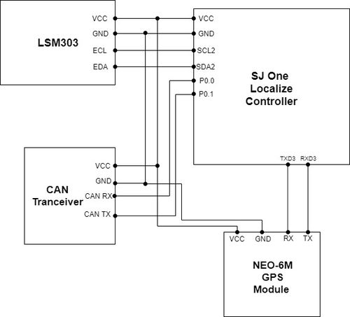
The geographical/localization controller (SJOne board) was connected to a compass and GPS module.
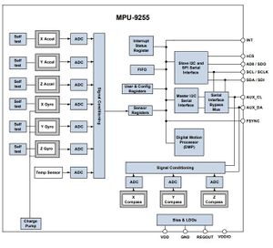
The compass that we are using for this project is an MPU-9255 which consist of an accelerometer, gyrometer, and three-axis magnetometer. For our purpose, only the magnetometer is used to find the direction of where the car is facing, which connects to the geographical controller via I2C. As you can see in the block diagram from this module, we will only need to connect to the AUX_DA (EDA) and AUX_CL (ECL), from the compass, to the SDA2 and SCL2, respectively. The connections to the auxiliary ports of this module will bypass the accelerometer and gyrometer completely.
The GPS module that was selected was a Ublox Neo-6M module. The GPS communicates with the geographical controller via UART.
Software Design
<List the code modules that are being called periodically.>
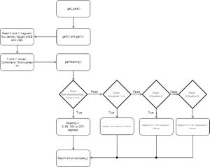
For the compass, the get_data() modules is being called periodically in the c_periodic_callbacks file in the 100 Hz function. We want the sensor data to be sent to the CAN bus at a 20 Hz frequency, which is implemented by using an if-statement and a modulo 5 on the count variable which results to updated sensor value at 20 Hz: if(count % 5 == 1){}
The get_data() function will return a structure called 'compass_t'. In this structure, it groups three data values for the heading of the compass, the x and y-raw value of the magnetic flux density as a signed 16-bit integer and the calculated heading, which returns as a float. When calling the get_data() functions, it retrieves the X and Y-raw values of the magnetic flux density and then calculates the heading as shown in the diagram below.
Technical Challenges
- Initial Communication with Device
- X and Y Magnetic Flux Value Variation when compass is stationary
- Single Measurement of Compass
- Calibration of the Compass Moudle
- Using the magnetometer, we received the magnetic flux density of the X and Y raw values from the sensor. Using the raw data, the x and y values were plotted on an X-Y scatter plot which resulted in a plot of the circular figure. We found the x and y-offset values which was used to place the circular plot in the middle of the axis.
- Heading of Compass
<Bullet or Headings of a module>
Unreliable GPS lock
<Problem Summary> <Problem Resolution>
Communication Bridge Controller & LCD
<Picture and link to Gitlab>
Hardware Design
Software Design
<List the code modules that are being called periodically.>
Technical Challenges
<Bullet or Headings of a module>
Insane Bug
<Problem Summary> <Problem Resolution>
Master Module
<Picture and link to Gitlab>
Hardware Design
Software Design
<List the code modules that are being called periodically.>
Technical Challenges
<Bullet or Headings of a module>
Improper Unit Testing
<Problem Summary> <Problem Resolution>
Mobile Application
<Picture and link to Gitlab>
Hardware Design
Software Design
<List the code modules that are being called periodically.>
Technical Challenges
<Bullet or Headings of a module>
Wifi Link Reliability
<Problem Summary> <Problem Resolution>
Conclusion
<Organized summary of the project>
<What did you learn?>
Project Video
Project Source Code
https://gitlab.com/cant-bus/cant-bus
Advise for Future Students
<Bullet points and discussion>


