F19: M&B (Morph & Blend)
Contents
Grading Criteria
- How well is Software & Hardware Design described?
- How well can this report be used to reproduce this project?
- Code Quality
- Overall Report Quality:
- Software Block Diagrams
- Hardware Block Diagrams
- Schematic Quality
- Quality of technical challenges and solutions adopted.
M&B (Morph & Blend)
Abstract
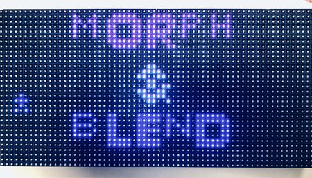
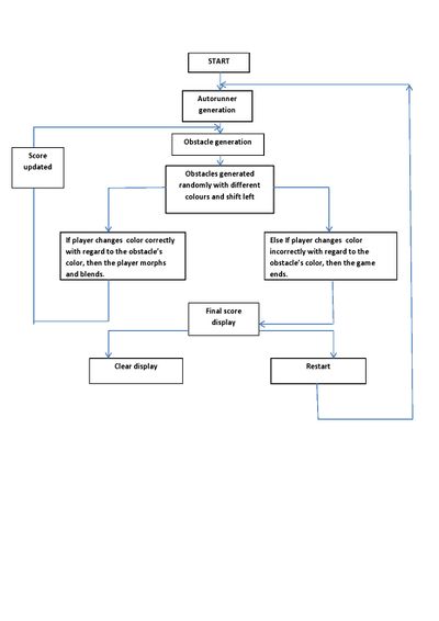
M&B is a unique and fast game in which the player has to blend and match with the incoming obstacles. The game demands good reflexes to jump and blend in with the approaching obstacles to keep moving forward. The player is required to control his cube-like character that moves to the right, left and forward directions to make long jumps and change color by these obstacles. Instead of the usual jumping over the barriers and pits, the player has to adapt to them by dynamically changing the character’s color before landing on the platform. SJTwo board will be used to implement the game logic, control the RGB matrix and the joysticks/switches. The RGB matrix will be used to display the real-time game statistics such as the player name and their score. The game ends if the player lands on an obstacle of a different color.
Objectives & Introduction
Objective
The objective of this project is to develop a simple, single-player 2D game using LPC174078 microcontroller on an LED matrix display. It focuses on integrating the micro-controller peripheral drivers, led drivers, mp3 player, button controller interface and the application software in FreeRTOS.The button controller interface consists of the button controls for changing color, to control the player's movement and to reset the game. The mp3 player is used to play the game background music.
There are four components in this project:
- The Display : A 32X64 LED Display Matrix acts as the display of the game.
- The Controller : The SJ Two Board computes the random obstacle generation and handles the movement and color blend of the player from the button control interface and transfers the information to the display using the GPIO pins.
- The Button Control Interface : The push buttons on the PCB designed for the game control, interfaced with the game reads the inputs given by the user and relays to the SJ One board to control the player.
- The MP3 music player : The game background music is played from the mp3 player and relayed to the SJ-Two board using the SPI bus.
Introduction
The Project consists of three main modules:
Button control module: It consists of 7 buttons for the player control; 4 for the different colours to switch, 2 for the directions and 1 for the game reset.
Display Module: It is responsible for controlling 32*64 LED Matrix interfaced to SJ Two Board.
Mp3 application This establishes communication to the display module using SPI.
About the game
- Player should match the colour of the approaching obstacles to score points by "morphing and blending".
- Obstacles of random colours are generated randomly.
- Button control interface enables the user to shift directions and also control the color of the player.
- The game can be reset at anytime using the reset button.
Team Members & Responsibilities
- Ryan Will
- PCB design
- MP3 implementation
- Shreeya Mahadevaswamy
- LED Matrix driver
- Game Logic- Obstacle
- Game control configuration
- Scoreboard
- Testing
- Shanmathi Saravanan
- LED Matrix driver
- Game Logic- Autorunner
- Game control configuration
- Testing
- Scoreboard
Schedule
| Week | Date | Task | Status | Completion Date |
|---|---|---|---|---|
| 1 | 10/10/2019 |
|
|
|
| 2 | 10/15/2019 |
|
|
|
| 3 | 10/22/2019 |
|
|
|
| 4 | 10/5/2019 |
|
|
|
| 5 | 11/16/2019 |
|
|
|
| 6 | 11/16/2019 |
|
|
|
| 7 | 11/19/2019 |
|
|
|
| 8 | 11/26/2019 |
|
|
|
| 9 | 12/3/2019 |
|
|
|
| 10 | 12/10/2019 |
|
|
|
| 11 | 12/17/2019 |
|
|
|
Bill of Materials (General Parts)
| PART NAME |
PART MODEL & SOURCE |
QUANTITY |
COST (USD) |
|---|---|---|---|
|
Purchased from Preet Kang |
2 |
50.00 |
|
Sparkfun [1] |
1 |
64.99 |
|
Amazon [2] |
6 |
7.00 |
|
https://www.amazon.com/Chanzon-Female-Connector-Security-Adapter/dp/B079RCNNCK/ref=sr_1_4?keywords=DC+Barrel+Jack+Adapter+-+Female&qid=1574052181&sr=8-4 |
1 |
5.75 |
|
Sparkfun 5V / 4A Power Supply |
1 |
12.95 |
Design & Implementation
The game design mainly consists of the LED drivers, PCB designs, button control interface for user control, mp3 implementation to play the background music for the game.
Hardware Design
The hardware design of the 32x64 RGB LED matrix panel which is the most important part of the project, uses four data lines namely A,B,C and D which can be addressed and used to control each LED which has following technical specifications:
Parameters:
- 2048 RGB LEDs
- 1/16 Scan Rate
- IDC Connector for Daisy Chaining
- 5V Supply Voltage
The figure and table below show the pin-out of the RGB LED matrix with description.
| Label | Name | Function |
|---|---|---|
| 1 | R1 | High R data |
| 2 | G1 | High G data |
| 3 | B1 | High B data |
| 4 | R2 | Low R data |
| 5 | G2 | Low G data |
| 6 | B2 | Low B data |
| 7 | A | A line selection |
| 8 | B | B line selection |
| 9 | C | C line selection |
| 10 | D | D line selection |
| 11 | CLK | CLOCK |
| 12 | LAT | LATCH |
| 13 | OE | Output Enable |
| 14 | GND | GND |
LED Matrix Control
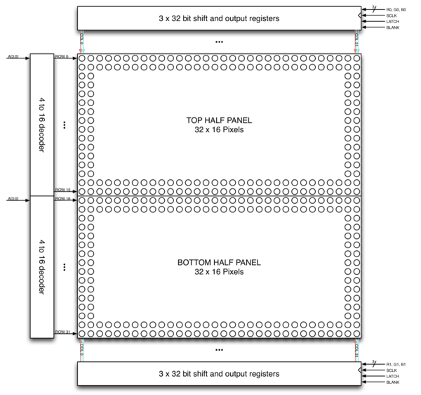
The LED panel contains 1024 RGB LEDs arranged in a matrix of 32 rows and 64 columns. Each RGB LED contains separate red, green, and blue LED chips assembled together in a single package. The display is subdivided horizontally into two parts, the top half and bottom half consists of 64 columns and 16 rows respectively.
There are different drivers for controlling display’s columns and another set of drivers for controlling rows. To illuminate an LED, the drivers for both the column and the row for that LED must be turned on. To change the color of an LED, the red, green, and blue chips in each LED package are controlled individually and have their own column drivers.
The panel contains six sets of column drivers; three for the top half of the display and three for the bottom. Each driver has 32 outputs. The three drivers for the top of the display drive the red, green, and blue chips in each of the 64 columns of LEDs in rows 0 to 15 of the panel. The three drivers for the bottom of the display drive the red, green, and blue chips in each of the 64 columns of LEDs in rows 16 to 31 of the panel. The red, green, and blue column drivers for the top half of the display are attached respectively to the R0, G0, and B0 data inputs. The red, green, and blue column drivers for the bottom half of the display are attached respectively to the R1, G1, and B1 data inputs. All six of the 32-bit drivers share common SCLK, LATCH, and BLANK signals.
The display is multiplexed and has a 1/16th duty cycle. This means that no more than one row out of the 16 in the top half of the display and one row out of the 16 in the bottom half of the display are ever illuminated at once. Furthermore, an LED can only be on or off. If both the row and column for an LED are turned on, the LED will be illuminated; otherwise, the LED will be off. To display an image, the entire LED panel must be scanned fast enough so that it appears to display a continuous image without flickering. To display different colors and different brightness levels, the brightness of the red, green, and blue LED chips within each LED package must be adjusted by varying the amount of time that each LED chip is on or off within a single refresh cycle.
Hardware Interface
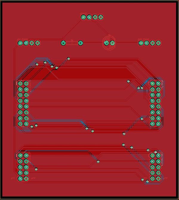
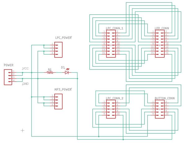
For the hardware, we designed a PCB board that would be used as a hub to connect the LPC4078, the LED Matrix, and the controls together. The images below show the PCB Board and the PCB schematic that were designed. The PCB features 26 pin connections that can be used to connect the pins of the LPC4078 to the LED Matrix, an MP3 decoder, a controller, or any other components. The PCB board was designed using the EAGLE PCB Design Software.
PCB Board Design
This is a screenshot of the PCB Board that was designed through EAGLE. All of the parts used for the design were plated through holes. This allowed for simple header pins to be soldered directly to the PCB rather than using surface mounted parts.
PCB Schematic Design
This is a screenshot of the PCB Board Schematic that was designed through EAGLE and used to build design the PCB Board. The schematic features a large number of header pins that can be used to connect the LPC4078 to a variety of components, including an LED matrix, a button controller, and an MP3 Decoder. Several pins were also added to supply both a VCC and a GND to all of the components used in the design.
Software Design
The entire software for the game including the APIs were written from scratch. A thorough understanding of the LED Display Matrix proved beneficial in writing suitable code for the display.
Logic
A led_matrixbuffer array maps onto the LED Display Matrix. A value overwritten in this two-dimensional buffer updates the corresponding Pixel value of the LED Matrix. The drawPixel function maps onto the led_matrixbuffer and updates the corresponding value.
The tasks run in parallel and are scheduled with the help of the task scheduler that updates the display regularly.
The main code logic blocks which are the random obstacle generation, obstacle motion enabling and obstacle color mismatch detection blocks are as follows: OBSTACLE GENERATION:
bool generate_obstacle_rand(void) {
 bool ret;
 uint8_t randomize_color = (rand() % 4) + 1; // generating random colour
 rand_row = (rand() % 17) + 9;  // generating a random row for obstacle generation
 while (!(((row_old - rand_row) >= obstacle_gap) || ((rand_row - row_old) >= obstacle_gap))) {  // loop  is used to generate a new row number in comparison with the last generated row number
   rand_row = (rand() % 17) + 9;
 }
 while (colour_old == randomize_color || ((colour_old == yellow1) && (randomize_color == cyan1))) {
   randomize_color = (rand() % 3) + 1;
 }
 if (randomize_color == cyan1) {
   randomize_color = yellow1;
 }
 int8_t row = rand_row;
 for (int8_t col = 63; col > 52; col--) {
     drawPixel(row, col, randomize_color);
     drawPixel(row + 1, col, randomize_color);
     ret = 0;
 }
 row_old = rand_row;
 colour_old = randomize_color;
 ret = 1;
 return (ret);
}
OBSTACLE MOTION LOGIC:
void shift_obstacle_left(void) {
 int8_t temp;
 for (int8_t row1 = 9; row1 < 28; row1++) {
   for (int8_t col1 = 0; col1 < 63; col1++) {
     ledmatrix_buffer[row1][col1] = ledmatrix_buffer[row1][col1 + 1]; // move all element to the left except first
   }
   ledmatrix_buffer[row1][63] = 0;
 }
}
OBSTACLE BLEND COLOR MISMATCH DETECTION:
bool detect_collision(void) {
 bool detect = 0;
 if (((ledmatrix_buffer[autorunner_row][4] != ledmatrix_buffer[autorunner_row][5]) &&
      (ledmatrix_buffer[autorunner_row][5] != 0)) ||
     ((ledmatrix_buffer[autorunner_row + 1][5] != ledmatrix_buffer[autorunner_row + 1][6]) &&
      (ledmatrix_buffer[autorunner_row + 1][6] != 0)) ||
     ((ledmatrix_buffer[autorunner_row + 2][4] != ledmatrix_buffer[autorunner_row + 2][5]) &&
      (ledmatrix_buffer[autorunner_row + 2][5] != 0)) ||
     ((ledmatrix_buffer[autorunner_row + 3][5] != ledmatrix_buffer[autorunner_row + 3][6]) &&
      (ledmatrix_buffer[autorunner_row + 3][6] != 0))) {
   detect = 1;
 } else {
   detect = 0;
 }
 return (detect);
}
MP3 Player Tasks:
void MP3_Play_Task(void *pvParameters) {
       BYTE decoder_buffer[512];
       mp3_decoder_init();
       while(1)
       {
               if(xQueueReceive(MP3Queue, decoder_buffer, 1000))
               {
                       //printf("track playing");
                       play_mp3_track(decoder_buffer);
               }
       }
}
void Read_MP3_Task(void *pvParameters) {
       while(1)
       {
               readMP3File();
               vTaskDelay(1000);
       }
}
MP3 Decoder Driver:
void mp3_decoder_init() {
   ssp__init(24);
   gpio_x__set_as_output(1, 28); //Set pin 1.28 as output for RESET signal
   gpio_x__set_as_output(1, 20); //Set pin 1.20 as output for DCS signal
   gpio_x__set_as_output(1, 31); //Set pin 1.31 as output for CS signal
   //gpio_x__set(0, 25, true); //Set pin 0.25 high initially
   //gpio_x__set(0, 26, true); //Set pin 0.26 high initially
   //gpio_x__set(1, 30, true); //Set pin 1.30 high initially
   gpio_x__set_high(1, 28);
   gpio_x__set_high(1, 20);
   gpio_x__set_high(1, 31);
gpio_x__set_as_input(0, 26); //Set pin 0.26 as input for DREQ
   write_to_decoder(SCI_MODE, 0x0800);         //Set up MODE register
   //write_to_decoder();                         //Set up Bass/Treble register
   write_to_decoder(SCI_CLOCKF, 0x2000);       //Set up Clock register
   write_to_decoder(SCI_AUDATA, 0xAC45);       //Set up AudioData register               `
   write_to_decoder(SCI_VOL, 0x2424);          //Set up Volume register
   uint16_t data1 = read_from_decoder(SCI_MODE);
   uint16_t data2 = read_from_decoder(SCI_CLOCKF);
   uint16_t data3 = read_from_decoder(SCI_AUDATA);
   uint16_t data4 = read_from_decoder(SCI_VOL);
   printf("SCI_MODE = %x\n", data1);
   printf("SCI_CLOCKF = %x\n", data2);
   printf("SCI_AUDATA = %x\n", data3);
   printf("SCI_VOL = %x\n", data4);
//u0_dbg_printf("mode data = %x\n", data);
}
void play_mp3_track(uint8_t buffer[]) {
   for(uint8_t byteIndex = 0; byteIndex < 16; byteIndex++)
   {
       while(!(gpio_x__get_level(0, 26)))
       {
           //vTaskDelay(1);
       }
       gpio_x__set(1, 20, false);
       //gpio_x__set_low(0, 26);
       //gpio_x__set_low(1, 30);
       for(uint16_t i = 32 * byteIndex; i < (32 * byteIndex) + 32; i++)
       {
           ssp__exchange_byte(buffer[i]);
       }
       while(!(gpio_x__get_level(0, 26)))
       {
           //vTaskDelay(1);
       }
       gpio_x__set(1, 20, true);
       //gpio_x__set_high(0, 26);
       //gpio_x__set_high(1, 30);
   }
}
Implementation
To play music from the MP3 decoder, the MP3 file needs to be pulled from an SD card and into a buffer, and the data needs to be fed to the MP3 Decoder through the SPI Bus.
HARDWARE IMPLEMENTATION:
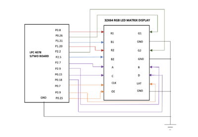
The hardware connection between the SJTwo Board and the RGB LED matrix display control pins is as illustrated in the following block diagram:
The pins R1, G1, and B1 were used to control the color that lights up in the upper 16 rows of the display matrix and R2, B2 and G2were used to control the lower 16 rows. Pins A, B, C, and D are used for row selection. Based on different combinations of R, G and B pin values different colors can be generated.
Testing & Technical Challenges
Developing a driver for the LED matrix...
The biggest technical challenge that we faced was interfacing the LPC 1758 micro-controller, with the Adafruit 32 x 64 LED matrix.
Adafruit (the 32 x 64 LED matrix's manufacturer) provides a basic tutorial on their website, in order to help with interfacing the LED matrix to a micro-controller. The tutorial briefly describes the functions of the pins on the board's input and output connector ports. It also describes how to connect jumper wires to the ribbon cable (which comes packaged with the board), which connects to the matrix's input and output connector ports. It assumes that the user will utilize an Arduino-type micro-controller to drive the matrix's RGB LED's.
Because we used the LPC 1758 to drive the LED matrix, our choices were to either adapt a third party driver library designed for an Arduino, or develop a new driver. We chose the latter option, as the third party Arduino-focused API's were difficult to fully understand. We also felt that developing our own driver would allow us to gain a strong understanding of all aspects of micro-controller to LED matrix integration. This proved useful both for firmware development and debugging.
The first part of developing the LED matrix driver, was learning how each of the 16 input pins affected the matrix display.
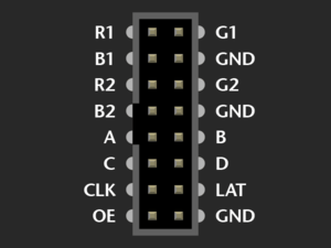
The LED matrix's input socket looked as follows:
GND...
The 3 GND pins were the easiest to understand. They provided a ground signal reference for the matrix's RGB LED's. The GND pins on the LED matrix were connected to GND on the LPC 1758, through a ground plane on the PCB, allowing the micro-controller and LED matrix to share the same signal reference.
A B C D...
Pins A, B, C and D, were used as control bits for the LED matrix's row multiplexer. The 32 x 64 matrix is made up of two individual 16 x 64 LED panels. Each panel contains 16 rows and 32 columns. The binary values of the multiplexer signals, A, B, C and D, are used to determine which row of LED's is being driven. Each panel drives the same row of LED's at a time, based on these values. For example, if A, B, C and D are set to 0000, then the LED's in the first row of each panel can be driven. If A, B, C and D are set to 0001, then the LED's in the second row of each panel can be driven. This pattern continues until A, B, C and D are set to 1111, which corresponds to sixteenth (bottom) row of each panel. We set our row iterating value, as i = (i + 1) % 16, so that A, B, C and D, would be set to 0000, after finishing latching data into the sixteenth row. This allowed the multiplexer to continuously loop through each row in each panel, from top to bottom. We applied a delay of 1ms after each row iteration, thereby setting the overall scan rate to 62Hz. This scan rate was too fast for the human eye to detect, which allowed the LED matrix to display objects steadily, without annoying flickering compromising the image quality.
R1 B1 G1
R2 G2 B2...
Pins R1, B1, G1 and R2, B2, G2, were the 6 control signals used to drive the matrix's RGB LEDs, different combinations of red, blue and green (depending on their binary values). R1, B1 and G1, controlled indiidual LED colors on the top panel (panel 1), while R2, B2 and G2, controlled individual LED colors on the bottom panel (panel 2). The way these color combinations manifested on the board, were as follows:
| R | B | G | COLOR |
| 0 | 0 | 0 | OFF |
| 0 | 0 | 1 | GREEN |
| 0 | 1 | 0 | BLUE |
| 0 | 1 | 1 | CYAN |
| 1 | 0 | 0 | RED |
| 1 | 0 | 1 | YELLOW |
| 1 | 1 | 0 | PURPLE |
| 1 | 1 | 1 | WHITE |
In order to understand how these signals drive individual LEDs on the matrix, one must understand the hardware that they control. The matrix's RGB LEDs are driven by 6 column drivers, each having 32 outputs. Each panel has 3 column drivers. Each column driver can drive 32 LED's in each panel, either red, green or blue (because each of the 3 column drivers controls one of these 3 colors). As a result, the 6 column drivers can drive up to 192 individual red, green and blue LED's (each RGB LED consists of 3 individual red, green and blue LED's) at a time.
CLK LAT OE...
Each column driver is composed of a serial data input, a blanking input, a shift register, and a parallel output register. Data bits are passed into the shift register on the rising edge of each clock cycle. The clock is controlled using the signal CLK. Because there are 32 RGB LED's per row, 32 clock cycles must occur, in order to drive all LED's in a row. After 32 bits of data are passed into the shift register, the LATCH signal (which is set low before shifting in data bits to the shift register) must be asserted, in order to transfer the data bits from the shift register to the parallel output register. Output enable (OE) is pulled low at this point, in order to enable the column driver. It is pulled high again, when transitioning to a new row. We designed our driver to operate on 32 bit, bit strings (of type uint32_t), in order to utilize all 32 LEDs in each row of the matrix. Each 32 bit string, was stored in a 32 element array of type, uint32_t. We assigned the base memory address of the array to a pointer, and used integer offset values to pass the different bit strings, stored in the array, into the matrix driver function. This method allowed us to pass 32 unique bit strings into all 32 rows of the LED matrix. The integer offsets corresponded to row numbers. For example an offset of 4, would increment the pointer, pointing at the memory address of row 0, by 4 memory addresses. Dereferencing the pointer with this offset (4), would give access to data bits governing the output of row 4 of the LED matrix (the fifth row).
For each row, we used a for loop (which iterated from 0 to 31) in order to shift all 192 data bits into the shift registers. We latched the data bits into the parallel output register, after shifting was completed, which allowed us to illuminate different individual LED's in each row. This allowed us to use 32 bit, bit strings, to create data structures and graphics.
The column driver also allowed us to give the illusion of motion, by turning different LED's on and off in adjacent rows.
MP3 Decoder...
There were problems with implementing the MP3 Decoder. When trying to decode the MP3 files, the speaker would not output any sound. The most likely cause of this problem was that there was an issue with the SPI bus, which was preventing the MP3 Decoder from getting the correct MP3 data.
Conclusion
This project was a fun and strenuous application of our engineering and project management skills.
After completing the driver labs during CMPE 244, we felt confident that we could develop a driver, for the Adafruit LED matrix, without using any third party libraries. We researched the hardware operations of the LED matrix and how to drive the RGB LED's. Once we could control LED's one at a time, the project evolved from an engineering problem into more of a creative exercise.
We faced some issues in implementing the player movement along with the updated color input. To move the player back and forth with the input of a button press and to store the data of the colour stored at each location was a challenge as we were clearing and redrawing the player at every location.
Overall I think the biggest lessons that we learned is project management based. We spent a lot of time choosing between various game designs and it forced us to start our final iteration later than we would have liked. However, we banded together and worked hard during the final few days of the semester to create this game.
If we had to do this project over again, we would plan to manage our time better and probably work on increasing the complexity of the game. We would also improve our PCB and MP3 player. We went with a simple design for this project, as none of us had much prior experience with PCB design or LED matrix. However, now that we understand EAGLE better, developing a better interfacing circuit would be much easier and less time intensive.
We would also implement a wireless controller, instead of having the same LPC 1758 drive the LED matrix and control the acceleration sensor. Since our player sprite only had one dimension of movement, we considered a wireless controller a bit overkill for the project, but looking back it would have heightened the player experience.
Overall this project allowed us to apply both or engineering fundamentals, as well as our creative design skills.
References
Acknowledgement
We wish to thank Preet and the ISA team for hosting this class. This was a fun project and a great learning experience for our group. We hope to be able to take CMPE 243 in the future.
References Used
- https://bikerglen.com/projects/lighting/led-panel-1up/
- FreeRTOS documentations
- 32x32 LED Matrix by Adafruit
- Adafruit Github Library
- Adafruit Github Library
- WikiPage by Preetpal Kang
- Sparkfun MP3 Decoder
Appendix
You can list the references you used.
