F19: Tetris
Contents
- 1 Project Title
- 2 Objectives & Introduction
- 3 Team Members & Main Responsibilities
- 4 Schedule
- 5 Parts List & Cost
- 6 Design & Implementation
- 7 Testing & Technical Challenges
- 8 Conclusion
- 9 References
Project Title
LED Matrix Tetris
Abstract
- Tetris is 2D tile-matching puzzle video game developed by software engineer Alexey Pajitnov in Soviet Russia around June 1984. The goal of the game is to create as many horizontal lines of a block as possible, and once the lines are completed it will disappear. The points will be granted by clearing the horizontal lines, the more horizontal lines it clear at once the more points will be given. If the Player failed to clear the lines and the blocks reach the top of the screen that stops the next block from falling the game ends. Our goal is to reproduce a similar version of a modern Tetris now with the knowledge we learned from our CMPE 244 lectures.
Objectives & Introduction
- The primary objective of this project was to create a game of Tetris using the SJTwo microcontroller and a 32x32 LED Matrix. Additionally, we would apply our understanding of FreeRTOS and the drivers we created throughout the course to our project development. Interfacing to the LED Matrix required developing a driver to draw to the matrix appropriately. Our game of Tetris was developed with standard inputs such as moving the piece left, right, place a piece down faster, and rotation. An additional input we added was enabling the player to save a piece for later use. Additional features for the project was the addition of music while playing a game of Tetris.
Team Members & Main Responsibilities
Administrative Roles
| Administrative Roles | ||||
|---|---|---|---|---|
|
Kevin Chan & Lawrence Wan | |||
|
Kevin Chan | |||
|
Yuming Cheng | |||
|
Yuming Cheng | |||
|
Lawrence Wan & Kevin Chan | |||
Technical Responsibilities
| Technical Responsibilities | ||||
|---|---|---|---|---|
|
Kevin Chan & Lawrence Wan & Yuming Cheng | |||
|
Kevin Chan | |||
|
Yuming Cheng & Lawrence Wan | |||
|
Lawrence Wan | |||
|
James Ding & Lawrence Wan | |||
Schedule
Team Deliverables Schedule
| WEEK |
START DATE |
END DATE |
TASK DETAILS |
STATUS |
|---|---|---|---|---|
| 1 | 8 Oct 2019 | 21 Oct 2019 |
Create and establish GitLab repository |
Complete (on time) Complete (on time) Complete (on time) Complete (on time) Complete (on time) Complete (on time) |
| 2 | 22 Oct 2019 | 4 Nov 2019 |
Create a Bill of Materials. |
Complete (Actual Completion Date: 10 Dec. 2019) Complete (on time) Complete (on time) |
| 3 | 5 Nov 2019 | 11 Nov 2019 |
Finalize the Wiki schedule for submission |
Complete (on time) Complete (Actual Completion Date: 22 Oct. 2019) Complete (Actual Completion Date: 4 Nov. 2019) |
| 4 | 12 Nov 2019 | 18 Nov 2019 |
Received the PCB and start working on connections |
Complete (on time) Complete (Actual Completion Date: 18 Nov. 2019) Complete (not time) Complete (on time) Complete (no time) |
| 5 | 19 Nov 2019 | 25 Nov 2019 |
Starting to assemble the enclosing |
Complete (Actual Completion Date: 15 Dec. 2019) Complete (Actual Completion Date: 18 Nov. 2019) Complete (Actual Completion Date: 2 Dec. 2019) Complete (Actual Completion Date: 9 Dec. 2019) |
| 6 | 26 Nov 2019 | 2 Dec 2019 |
Polishing the Hardware and Software for project. |
Complete (on time) Complete (on time) Complete (Actual Completion Date: 15 Dec. 2019) Complete (Actual Completion Date: 15 Dec. 2019) |
| 7 | 3 Dec 2019 | 9 Dec 2019 |
FIELD TESTING - CRITICAL WEEK |
Complete (on time) Complete (on time) Complete (Actual Completion Date: 15 Dec. 2019) |
| 8 | 10 Dec 2019 | 17 Dec 2019 |
All hands on testing and final bug fixes. |
Complete (on time) Complete (on time) Complete (Actual Completion Date: 18 Dec. 2019) Complete (Actual Completion Date: 18 Dec. 2019) |
| Final | 18 Dec 2019 |
DEMO: Final Project |
Complete (on time) Complete (on time) |
Parts List & Cost
Bills of Materials
|
Materials |
Quantity |
|---|---|
|
|
|
|
|
|
|
|
|
|
|
|
|
|
|
|
|
|
|
|
|
|
|
|
Detail Costs
| PART NAME |
PART MODEL & SOURCE |
QUANTITY |
COST (USD) |
|---|---|---|---|
|
|
|
|
|
|
|
|
|
|
|
|
|
|
|
|
|
|
|
|
|
|
|
|
|
|
|
|
|
|
|
|
|
|
|
|
|
|
|
|
|
|
|
|
|
|
|
|
|
|
|
|
|
|
|
|
|
|
|
|
|
|
|
|
|
|
|
|
|
|
|
|
|
|
|
|
| Total Cost: |
|
Design & Implementation
Hardware Design
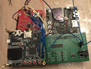
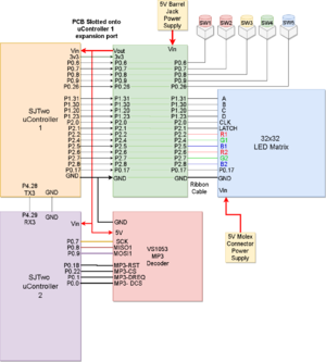
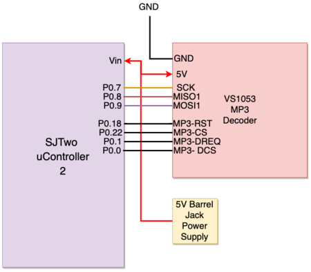
- The initial design approach of the project consisted of one SJTwo micro-controller, a 32x32 LED matrix display, and a PCB to help simplify interfacing the two in terms of power and wiring. Having made good development progress, it was decided to include music along with the game, which involved interfacing the SJTwo controller with a (VS1053) MP3 decoder. Approximately a week later, development for the MP3 decoder was delayed due to unexpected behavior in interfacing with the MP3 decoder while using SPI bus 2. Unfortunately, by the time the decision to add music was confirmed, a PCB design was already made and had been sent to manufacture. Consequently, the pre-determined pin configurations (used to interface to the LED matrix) had occupied the available working SPI buses such that using another SPI bus instead was not possible. After thorough contemplation and debate about hardware complexity, development with a second SJTwo micro-controller began as soon as possible to interface with the decoder using SPI1.
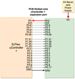
Micro-controller 1
| Label | Function | Pin Connection |
|---|---|---|
| 1 | Switch 1 | Pin 0.6 |
| 2 | Switch 2 | Pin 0.7 |
| 3 | Switch 3 | Pin 0.8 |
| 4 | Switch 4 | Pin 0.9 |
| 5 | Switch 5 | PIn 0.26 |
| 6 | Tx3 to MP3 board | PIn 4.28 |
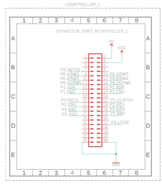
| 7 | High R data | Pin 2.2 |
| 8 | High G data | Pin 2.4 |
| 9 | High B data | Pin 2.5 |
| 10 | Low R data | Pin 2.6 |
| 11 | Low G data | PIn 2.7 |
| 12 | Low B data | PIn 2.8 |
| 13 | A line selection | Pin 1.31 |
| 14 | B line selection | Pin 1.30 |
| 15 | C line selection | Pin 1.20 |
| 16 | D line selection | Pin 1.23 |
| 17 | CLOCK | Pin 2.0 |
| 18 | LATCH | Pin 2.1 |
| 19 | Output Enable | Pin 0.17 |
| 20 | GND | Pin GND |
Micro-controller 2
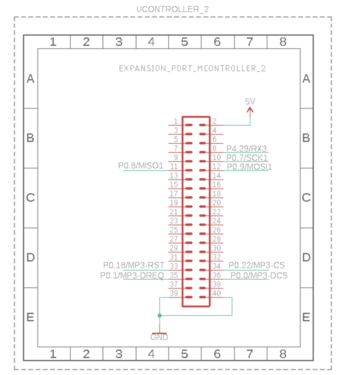
| Label | Function | Pin Connection |
|---|---|---|
| 1 | Rx3 from the Gaming Driver | Pin 4.29 |
| 2 | SCK1 to mp3 | Pin 0.7 |
| 3 | MISO to mp3 | Pin 0.8 |
| 4 | MOSI to mp3 | Pin 0.9 |
| 5 | MP3 CS | PIn 0.22 |
| 6 | MP3 Reset | PIn 0.18 |
| 7 | MP3 Data request | Pin 0.1 |
| 8 | MP3 Data CS | Pin 0.0 |
| 9 | GND | Pin GND |
PCB Design
- The PCB design began with the primary objective of interfacing the SJTwo microcontroller with the LED Matrix Display with ease. Initially, the second objective was to create a power circuit to power the SJTwo microcontroller and led matrix, however, later decisions have led to re-purposing the circuit post-manufacturing of the PCB. The third objective was to create circuits for external buttons to operate the game.
PCB SJTwo Microcontroller to LED Matrix Pin Connections
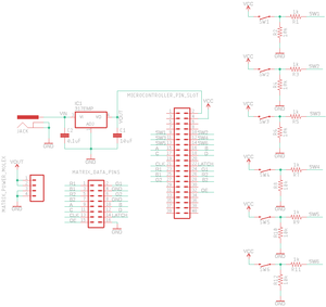
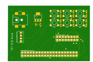
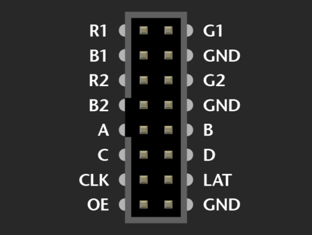
- Interfacing the microcontroller and matrix with ease meant avoiding the use of loose wiring as much as possible. Since the matrix itself came with a ribbon cable, it was decided that we design a PCB around using the ribbon cable to interface it with the microcontroller. It was decided to slot the PCB with the microcontroller with 2x20 through-hole headers (labeled as MICROCONTROLLER_PIN_SLOT in the schematic). The pre-selected pins needed from the microcontroller to interface with the matrix are then connected to 2x8 header pins (labeled as MATRIX_DATA_PINS) which correspond to the pinout of the 32x32 LED Matrix data pins(shown in Hardware Interface section).
PCB Power Circuit
- The initial design of the PCB power circuit was to power one microcontroller and the led matrix. The power circuit consists of a barrel jack connector(labeled JACK as shown in the schematic) connected to a 5V voltage regulator. The voltage regulator Vin and Vout terminals are connected to 0.1 micro-farad and 10 micro-farad capacitors, respectively, to ensure that 5V is supplied to the hardware connected. As mentioned before, later decisions to add the VS1053 decoder had re-purposed the power circuit to power both SJTwo microcontrollers and the decoder, whereas the matrix had an independent 5V power supply.
PCB External Button Circuit
- 6 GPIO input circuits were included in the PCB design to include the attachment of external buttons, as shown in the PCB schematic below. On the PCB itself, the button circuits are labeled "sw1" through "sw6," as shown in the PCB manufacture model. The pins configured as inputs for button use are P0.6(sw1), P0.7(sw2), P0.8(sw3), P0.9(sw4), P0.26(sw5), and P0.25(sw6).
Hardware Interface
Configuration of the 32x32 LED Matrix
- The 32x32 LED matrix was purchased from Adafruit. The pinout diagram below shows the pins that are needed to be interfaced with the SJTwo Microcontroller. Descriptions of each of the pins are provided in the following sections. The most straight forward of the pins below is ground, where each of the ground pins was connected to a ground plane on the PCB where it was grounded with the SJTwo board.
| Label | Name | Function | Pin Connection |
|---|---|---|---|
| 1 | R1 | High R data | Pin 2.2 |
| 2 | G1 | High G data | Pin 2.4 |
| 3 | B1 | High B data | Pin 2.5 |
| 4 | R2 | Low R data | Pin 2.6 |
| 5 | G2 | Low G data | PIn 2.7 |
| 6 | B2 | Low B data | PIn 2.8 |
| 7 | A | A line selection | Pin 1.31 |
| 8 | B | B line selection | Pin 1.30 |
| 9 | C | C line selection | Pin 1.20 |
| 10 | D | D line selection | Pin 1.23 |
| 11 | CLK | CLOCK | Pin 2.0 |
| 12 | LAT | LATCH | Pin 2.1 |
| 13 | OE | Output Enable | Pin 0.17 |
| 14 | GND | GND | Pin GND |
- The panel is broken up into two 16x32 pixel panels and uses 32-bit shift registers to draw an image to the display. Each row has its own shift register that requires pixel colors to be shifted in, and have the output-enable (OE) to be toggled to display one frame. It should be noted that latch is required to have the shift register retain a drawn row. To make it appear to have a moving or still image, the frames must be drawn quickly enough (in our case its 100 Hz) such that the human eye can't detect that the image is being drawn.
Color Inputs (R1,R2,G1,G2,B1,B2)
- R1,R2,G1,G2,B1,B2, correspond to the color (Red, Green, Blue) that will be shifted in the shift register that will be displayed onto the LED matrix. On our display, the colors are shifted in from left to right. The number associated with each pin, determines if it is on the top or bottom half of the display. For example, if R1, B1 and G1, are set to high, then the output color will be white. GPIO pins from the SJTwo board were used to configure these pins to control color. To reduce the amount of clock cycles to draw an image, we draw both top and bottom images at the same time. More explanation of this is seen below.
Address Inputs (A B C D)
- A, B, C, D, pins correspond to the addressing of each row that the colors R1,R2,G1,G2,B1,B2 will be written to. GPIO pins were used to select which row was being drawn, with D being the most significant bit. The address inputs controls both top and bottom partitions of the display at the same time. So, you can draw both top and bottom at the same time by configuring your colors separately inputs separately.
CLK, OE, LAT
- OE is for output enable. Without this pin pulled low (active low), nothing will be displayed on the matrix. To have better visual effects, it should be toggled low on the completion of clocking in one row. If it remains low the entire duration of drawing, you can visually see the pixels move from left to right. CLK is the clock signal for shifting in colors for the shift registers. For more control, we used a GPIO pin instead of PWM to manage the cycles of how we draw one frame/image. The LAT single is used for when a full frame is put into shift register, and is ready to be outputted to the display. For us, this signal was toggled at the same time as output enable.
Matrix Driver
- To easily represent our matrix in our software, our driver contained 3 x 32 x (32-bit integers). Each color (red, green, blue) had its own 32 integer array. How this worked was each integer represented one row, and each bit in an integer represented one pixel. So for example, led_board_blue[0], would mean row 0 for the color blue, and you can manually set and clear bits to draw different pixels. An API was written so setting and clearing pixels was easily manipulated. Our API also allowed the setting of all colors in different combinations so it was easier later for us to create the Tetris game board. The display task would call the draw function every 100 Hz to redraw the display using these arrays.
Interfacing with the VS1053 MP3 Decoder
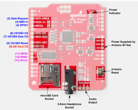
| Label | Name | Function | Pin Connection |
|---|---|---|---|
| 1 | MP3-DREQ | Decoder Data Request | Pin 0.1 |
| 2 | MP3-CS | VS1053 Chip Select | Pin 0.22 |
| 3 | MP3-DCS | VS1053 Data CS | Pin 0.0 |
| 4 | MP3-RST | VS1053 Reset | Pin 0.18 |
| 5 | MOSI | SPI Bus (Master Output Slave Input) | Pin 0.9 |
| 6 | MISO | SPI Bus (Master Input Slave Output) | Pin 0.8 |
| 7 | SCK | SPI Clock | Pin 0.7 |
| 8 | +5V | +5V | PCB Vout |
| 9 | GND | GND | GND |
Interfacing Two SJTwo Boards
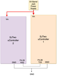
- Interfacing the two SJTwo microcontrollers was done simply using UART3. Microcontroller 1, (interfaced with the LED Matrix) consists of performing the Tetris game functionality, whereas, Microcontroller 2(interfaced with the MP3 Decoder) plays the music concurrently with the game.The TX3 P4.28 was used by Microcontroller 1 and is connected to RX3 P4.29 of Microcontroller 2. Both grounds of each board must also be connected. The BAUD rate of both controllers was initialized to 115200 bps.
Software Design
Tetris Game Design
Game Board Layout and Design
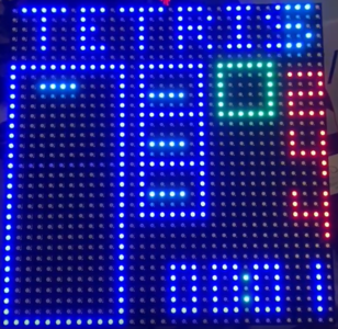
- Our game features a standard Tetris layout, which is 10 by 24 pixels. In the green square is the saved player piece, and the 3 squares adjacent to the main game board is the next 3 pieces that the player will have to play with. The timer for total player game time is located on the bottom right, and the top displays the player score. As per Tetris rules, any line cleared by the player is granted 100 points, and 800 for Tetris.
Static Game Board with Moving Pieces
- Since Tetris features a static game board with shifting pieces, we didn't want to have to redraw the game board onto the display every time. We have a function that only draws the static images (the game board square, the save box, and the 3 future pieces). On top of that, we also save a "live" game board that changes on every piece move. This "live" game board includes all the moving pieces (the timer, the actual predicted pieces, and the player game board that the user plays on). To get the final image seen on the display, we OR them together, and that allows us to only change what we need to change without modification of static drawings. From here, we have a separate API that allows us to draw on the live game board, and allows our coordinate plane to match the 10 by 24 and not the 32 by 32 plane. This system allowed a simpler way of manipulating the game board with coordinates that made sense for us to modify, instead of counting pixels of the display.
Tetris Pieces on the Game Board
- Each game piece in our Tetris game is contained in a struct that contains 4 (x,y) points for the current position, 4 (x,y) points for the previous position, and an identifier that lets the game know what type of piece it is. The previous position is necessary for us to redraw the last position that the piece was where it did not have a collision. Our object collision algorithm attempts to draw the piece at the current location (current location is changed from player action, or from the piece dropping due to time). If the piece lands on a tile that is occupied (there is another color already present - from hitting an edge of the board or hitting another piece), it will revert to the previous position and either 1. disregard the change (from a rotation or trying to move into the wall), or 2, have the piece stay because it collided with an already placed piece. Since the piece has (x,y) coordinates that match the coordinate plane of our game board, we draw the piece by ORing it with the game board and the rest of the drawing is taken care of. We also ensure to clear the previous position before drawing it again so there isn't a piece shadow.
Tetris Piece Rotation
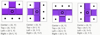
- One of the fundamental game logic in Tetris is enabling the player to rotate a piece currently in play. Each piece (besides the square or "hero" piece) should rotate while retaining its respective shape and should do so without conflicting with the boundaries of the game as well as other pieces. The methodology of developing the rotate function for our Tetris game is to rotate a piece in only one direction, left. Every time the rotation function is called (by button press) the current piece in play will rotate left once. To do so, the function takes in a struct that contains not only the x and y points of the current piece in play but also an integer color identifier. This id determines which piece to rotate. To rotate the x and y points of the current piece in play, a center point was chosen for each Tetris piece and its other points would then change x and y positions with respect to the center point which doesn't change positions at all. All possible rotation positions of a Tetris piece is tracked by four states(max). Each time the rotate function is called, a state counter will increment through each state until the counter reaches 4, at which the counter will revert back to 0 with the use of modulo. To ensure that a piece, after rotating, does not "phase" into the side boundaries, a check was made to disable rotation if the position of the piece in play is next to the game boundaries. To ensure that a piece does not rotate into another piece, another check was implemented to check if the next position is occupied by another piece. If the next position is occupied by any other piece, the current piece will revert back to its original position before calling the rotate function with the use of concurrently tracking the current and previous piece position.
Tetris Piece Saving
- The save-piece feature functions as a means for the player to save the piece currently in play. The save function methodology is similar to how we draw the next pieces queued in the "next piece boxes" statically drawn. Once a player saves the current piece in play, its color identifier(stored in a struct) is taken in as a parameter to indicate which piece to draw into the "save box" as a static image. If there is already a piece saved in the save box, then the last piece that was saved is swapped out with the current saved piece. The piece that was swapped out is then pushed out to become the current piece in play(allowing the player to make some game-changing moves!). This feature, however, has a particular caveat to consider. The save-piece function once after being called once, can only be called again once the piece in play(following a save) has been placed. This ensures that the player does not repeatedly keep saving or swapping out the previously saved piece repeatedly, which could potentially never progress the game at all.
Tetris Difficulties and Piece Auto Drop
- To create difficulties in our game, our game modes change the rate at which the piece drop is called. On easy difficulty, the piece drop function is called once every second. Medium drops every 500 ms and hard drops every 200 ms. Without the auto drop feature, the player would have an infinite amount of time to position their piece to their desired location. The purpose of the drop function is to decrease the Y coordinates of the piece by one, and also check if decreasing the piece coordinates by one hits another piece, or is unable to move further down from the start position (this is considered a game failure condition since it means there is nowhere for the next piece to be placed due to collision). If the end game scenario is triggered, it will wake up a high priority task that will suspend all other tasks related to the game while it performs an animation to clear the game board.
MP3 Design
MP3 Decoder Initialization
- To initialize the MP3 decoder, we first setup all the pins with their proper input/output/function configurations. We then configure the decoder registers by selecting the MP3 chip select pin and writing data over SPI. These include the mode (default), clock frequency multiplier (3x), volume (max), and audio (44100 Hz stereo data). We then flush the mp3 decoder, sending it 2500 0 bytes.
Reading the MP3 File from a Micro-SD
- We create a low priority task (mp3sdcard) to read from the micro-controller's SD Card reader. mp3sdcard task first opens the mp3 file on sd card, and determines the size. Afterwards, it reads in 512 bytes at a time to a global array (whenever the music playing task has finished playing the previous 16 bytes) and sets a global variable (sdready) to true. It will continue to do this until the file has been completely read, and then start over from the beginning.
Feeding the Decoder and Playing Music
- We create another low priority task (mp3_task) to play music. If the mp3Request pin is currently set, it delays. Otherwise whenever sdready is true, it selects Data chip select line, and sends 32 bytes over the SPI bus. It then deselects data chip select and redoes this 16 times (sending the 512 bytes that have been read). After it has sent all 512 bytes, it sets sdready to false so the sd card task knows to read in the next 512 bytes. It continues to repeat this process for as long as mp3sdcard reads in data to the array.
Playing Tetris and Music
Microcontrollers Working Together
- Microcontroller 1 is interfaced with the LED Matrix to play the game of Tetris. It is also interfaced with Microcontroller 2 through UART(using UART3), which plays music. The design approach to play Tetris and music concurrently, was to have microcontroller 1 send a signal through UART to
- Microcontroller 2, which then utilizes a UART read task which polls for a byte(signal) sent from microcontroller 1. A music control task then checks the byte(signal) to determine whether to resume or suspend the MP3 music and SD card read tasks. When a game mode of Tetris is started, in the menu task of microcontroller 1, a byte(signal), "p" is sent over UART to the music control task of microcontroller 2 to resume the MP3 music and SD card read tasks. Conversely, if the game is over, a signal "s" will be sent to the music control task and suspend both the MP3 music and SD card read tasks, and stops playing music.
Implementation
Steps to LED Matrix Driver
- Step 1: Initialize GPIO pins and matrix array map
- Step 2: Disable latch and output enable
- Step 3: Address first row
- Step 4: Shift in colors determined on matrix map
- Step 5: Clock in each color, until row is complete (32 times)
- Step 6: Enable output enable and latch
- Step 7: Address next row, repeat steps 3-5 until you complete drawing one frame (16 times - since the display is divided in half).
Gaming Logic: Rotate
- Step 1: Get the current location of the Tetris blocks from the LED matrix Driver
- Step 2: Choose the center of the block that will remain unchanged, and get the coordinate of the center bit in X and Y.
- Step 3: Shift left by rotating the dots around the center dot to the corresponding location. Ex. When shift T shape block to the left we move the top dot to the left of the center dot (so the top dot will be ( X - 1, Y) where X and Y are from the center blocks), and then the left dot to the bottom and right to the top of the center dot (So the Left dot will be (X, Y- 1) and right dot will be (X, Y + 1)).
- Step 4: There will be total of four State for the rotation for each blocks as shown on the example figure below.
- Step 5: Repeated step 1 to 4 for other blocks.
Gaming Logic: Save
- Step 1: In the "Tetris-save-piece" function, get the color identifier from the current piece in play.
- Step 2: Based on the color id of the current piece in play, pass the id as an integer into the game-board-draw function.
- Step 3: The game board draw function will draw a static image of the selected piece into the save space box.
- Step 4: Once a piece is initially saved, in the Tetris-save-piece function, the color id is stored into a variable, ready to be pushed out to play.
- Step 5: If another piece is saved. The color id of the latest piece saved will replace the color id of the last saved piece.
- Step 6: Push the last piece saved as the current piece to play and reinitialize its position such that it starts from the top.
- Step 7: Checks must be made to prevent the user from abusing the save over and over again. This is done in the game logic task (in main) by implementing a state counter(starting from state 0). When a piece is initially saved, the current piece will be updated to the next piece queue, and the piece will be drawn into the save space,then state counter increments to the second state(state 1).
- Step 8: In state 1 (when another piece is saved), it will swap the last saved piece id with the current piece, as well as re-initialize the current piece in play to push out the last piece saved to play. State counter increments again.
- Step 9: In the last state, (state 2), following a first save press, it will set a bool which enables swapping saved pieces only when the current piece in play following an immediate save press has been placed (when complete == true).
Gaming Logic: Shift
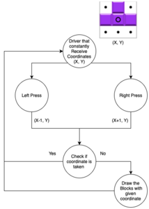
- Step 1: Wait for a button press, either left or right button
- Step 2: Depending on which button is pressed, move one position to the left or right by subtracting 1 or adding 1 to the X coordinates of current coordinates found within the piece data structure.
- Step 3: Check to see if new current position is in collision with any of the game board boundaries or already placed game pieces. If there is collision, go to step 4, if not go to step 5.
- Step 4: A collision has occurred, Tetris pieces can't shift into other pieces or boundaries. Revert current coordinates to previous coordinates found within the data structure.
- Step 5: Draw current coordinates of piece
Gaming Logic: Down
- Step 1: Shift all current coordinates down by 1. Subtract from all Y coordinates (4 total).
- Step 2: Check if the "new" coordinates intersect with any points - compare and see if any those coordinates have any color written to them. If yes, go to step 3, if no go to step 4.
- Step 3: The change was not accepted because of intersection, revert coordinates current coordinates to saved previous coordinates found in data structure
- Step 4: Draw the current coordinates for the shape - the shift was accepted. If step 3 was run, set a flag - this piece is now no longer playable and will become part of the game board and a new piece will be needed to be generated.
Steps to MP3 Design
- Step 1: Initialize SPI1, and construct pins with SPI functionality to interface the microcontroller to MP3 Decoder, as well as necessary GPIO pins as decoder control signals(xCS, xDCS, DREQ).
- Step 2: Initialize the MP3 decoder by writing to the command registers. This includes decoder operation frequency, decode time, volume, and song sample rate.
- Step 3: Open mp3 file from SD card, and read 512 bytes from the mp3 file at a time.
- Step 4: Based on the position of the song, take the respective 32 bytes of the 512 bytes read from the decoder and perform (SSP)write exchange to the decoder.
- Step 5: Music control task evaluates bytes from the UART read task which receives bytes sent from the other microcontroller which plays Tetris to indicate whether to play or stop music when a game of Tetris is started or when a game is over.
Microcontroller to Microcontroller Communication
- Step 1: Initialize UART3 on both microcontrollers with same BAUD RATE
- Step 2: When a game of Tetris is started in the menu-logic-task (in microcontroller 1), a byte, "p" will be sent through UART3 to the uart-read-task of microcontroller 2 to start playing music. When a game of Tetris has reached game over, a byte "s" will be sent to stop playing music.
- Step 3: In microcontroller 2, a music-control-task will evaluate the byte received (from microcontroller 1) in the uart-read-task. If the byte is "p," resume the tasks that send bytes to the decoder and read bytes from the sdcard. If the byte is "s," suspend the tasks that send bytes to the decoder and read bytes from the sd card.
Testing & Technical Challenges
Bug/issue name
|
Bug/issue name |
Description |
Solution |
|---|---|---|
|
|
|
|
|
|
|
|
|
Conclusion
- Overall, we had all found this project enjoyable and had a lot of takeaways from this class and project. Our Tetris game successfully runs with different game modes and also with a low CPU usage, <20% for the entire game (display runs at 16%). From this project, we not only learned how to write drivers for a display that had no manual, but we utilized all of our class knowledge into one project (drivers, FreeRTOS, PCB, power circuits, communication between two boards, debugging, GiT). We used our leadership and organizational skills to coordinate, and communicate with each other such that our project progress went forward without issue. Despite having issues in some development with the MP3 player and our PCB, we adapted and found an alternative solution to get it to work. From this project, we also understood the importance of planning ahead and getting work done early. We all strongly feel that through our experience through this project and class, we can use the knowledge gained from this class on future projects and job interviews. This class reinforced the idea that knowledge is about understanding and applying versus memorization and tests.
Future Work
- Further work to be considered for this project is to consolidate the game of Tetris and playing music together to one SJTwo Board. This can be done using a revised PCB layout which would make it so that the pins used for interfacing the controller to the LED matrix would free up SPI Bus 1. Additional work can be made to the current enclosure by having a single enclosed system, which would combine the controllers, decoder, buttons, and the LED matrix into one. Other work that can be made is to replace the buttons for the left and right shifts with the acceleration sensor on the SJTwo microcontroller or maybe even use the joystick as the inputs to minimize the use of wires and save more space within the enclosure. Other additional features we can include in the future are built-in speakers and have the enclosure powered by only one power supply.
Website Links
Project Video
Project Source Code
Project Presentation
References
Acknowledgement
- We would like to thank our professor Preetpal Kang for designing such a wonderful course which made us capable of developing our own game. Your consistent feedback and guidance were highly appreciated. The credit goes to our entire team, Tetris. With full support and cooperation from each other, we were successfully able to complete this project as planned.
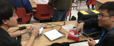
- Unfortunately, we didn't have the group photo taken together. Thus, we will just display the photo of our two team leaders as our group project representatives.
References Used
- CMPE 146 - MP3 Project Coding
- Datasheet Reference
- MP3 Decoder
