S16: SmartDoorLock
Contents
SmartDoorLock
Abstract
The frustration when you forget or lose the keys to your door is a common experience. SmartDoorLock provides a mechanism to lock and unlock your door with just your mobile phone, using bluetooth communication. The door also opens automatically when it senses an object approaching from the inside. An additional feature in the project is that a display near the entrance informs you about the weather outside, and gives friendly suggestions accordingly.
Objectives & Introduction
- Communication between Bluetooth Module and Android app
- Locking and unlocking electric strike via Bluetooth with password protection.
- Detecting motion using PIR motion sensor.
- Automatic unlocking the door based on motion detection.
- Reading temperature and displaying suggestions.
Team Members
- Arpita Ramanath
- Sravani Aitha
Responsibilties
- Circuit design for Electric door strike
- Establishing Bluetooth communication between SJone Board and Android app using Uart.
- Building power circuits for PIR motion sensor, LCD and Electric door strike
- Interfacing LCD module with SJone Board using Uart.
- Overall Circuit Integration and Testing.
Weekly Schedule
| Week# | Date | Task | Status |
|---|---|---|---|
| 1 | 4/26/2016 |
|
Done |
| 2 | 4/26/2016 |
|
Done |
| 3 | 5/03/2016 |
|
Done |
| 4 | 5/06/2016 |
|
Done |
| 5 | 5/10/2016 |
|
Done |
| 6 | 5/13/2016 |
|
Done |
| 7 | 5/17/2016 |
|
Done |
| 8 | 5/20/2016 |
|
Done |
Parts List & Cost
| Parts | Cost* |
|---|---|
|
PIR Motion sensor |
$13.87 |
|
Electric Door Strike |
$24.22 |
|
LCD |
$10.99 |
|
BTBee Pro Bluetooth Xbee wireless Module |
$14.99 |
|
SJ-One Board |
$80 x 2 |
Design & Implementation
System Schematic
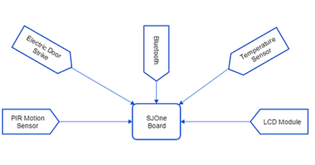
SmartDoorLock system is designed in a way that the door can be locked and unlocked using an Android app. It also detects motion when someone approaches the door towards the exit. Moreover, an LCD module is fitted near the exit which displays the outside temperature and provides friendly suggestions to the person exiting the door. It has the following components integrated.
- Electric Door Strike: To unlock the door when user sends unlock signal through blurtooth.
- Bluetooth Module: To establish a connection from Android app to SJone Board
- Android app: Application to communicate with the SJone board over Bluetooth.
- PIR Motion sensor: Detects motion if any person is approaching the exit. Based on sensor readings, SJone board sends a signal to electric door strike to unlock the Door.
- Temperature Sensor: SJone board receives outside temperature using temperature sensor and passes it to the LCD to display.
- LCD: To display outside temperature and suggestions to the person exiting the door.
Overall Algorithm
- Create two binary semaphores, which are waiting on Lock or Unlock signals from either Bluetooth or Motion sensor.
- As soon as Android app sends a open signal followed by correct password over Bluetooth, Give unlock semaphore.
- If PIR senses motion, Give unlock semaphore.
- If motion detected, wait until there is no motion and give Lock semaphore.
- If lock message is received through Bluetooth or wait time elapses after open message from Android app, Give Lock semaphore.
- Take the semaphore as soon as it is given and lock or unlock the electric door strike accordingly.
- In Parallel, keep updating LCD periodically with outside temperature and friendly suggestions.
Hardware Design
Electric Door Strike
The door strike being used in this project is of the type "fail-secure". This means that when there is no power being supplied to the strike, it remains locked. When a DC power supply of 12V is given, the strike unlocks, which can be detected by the characteristic clicking sound it makes.
The 3.3V supplied by our SJOne board is not sufficient for operation of the strike, which needs 12V. Hence, we designed a power supply circuit to supply the strike with 12V. The circuit consists of a 12V supply, a 15V to 12V voltage regulator and a couple of capacitors.
SJone Board - Electric Door Strike Interface
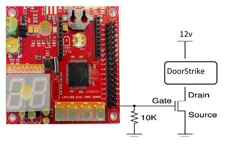
In order to control electric strike operation using SJOne board, it is interfaced using NMOSFET as shown in the image. GPIO pin is used as input to NMOSFET, Electric Door strike unlocks when GPIO pin outputs high otherwise it gets locked.
Bluetooth Module
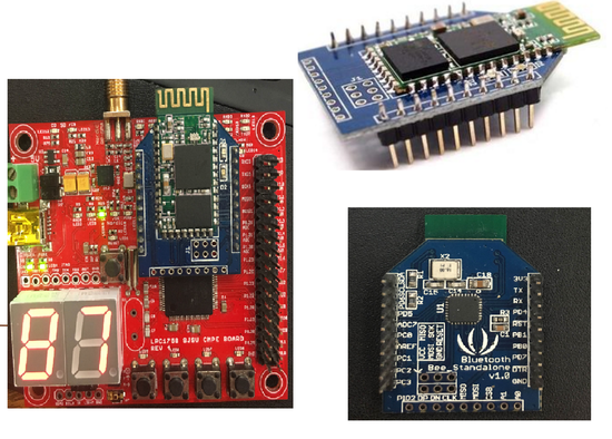
The bluetooth module we are using is the BTBee Pro Xbee Wireless Bluetooth Module from Adafruit. The pins of this module are perfectly compatible with the pins of the SJOne board such that it can be directly fixed on to the board (as shown in the diagram).
The bluetooth module is interfaced with SJOne using UART2. When a connection is established, it is possible to send and receive messages via bluetooth between the Android App and SJOne board. This section does not require any other hardware.
PIR Motion Sensor Module
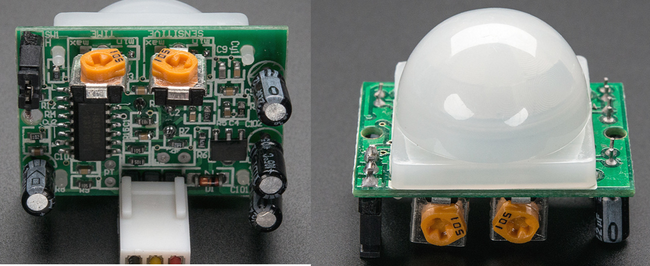
The PIR Motion Sensor from Adafruit allows us to sense motion, usually used to detect whether a human has moved in or out of the sensor's range. The sensitivity of this particular sensor is upto 20 feet. It needs a DC power supply of 5V. The circuit we are using to supply 5V to the sensor is similar to the 12V power supply circuit that was designed for the electric door strike. The sensor is interfaced with the SJOne board. The output wire of the sensor is connected to a GPIO pin (made as input) on the SJOne board.
When motion is detected, a logic "1" is sent via the output wire of the sensor to the board. When there is no motion detected, the SJOne board receives a logic "0".
LCD Module
A 20x4 LCD(CM 204-1) module along with a LCD driver by SJValley Engineering is used in the project. The LCD is provided a 5V DC power supply from the same circuit that provides power supply to the motion sensor. The connections between the SJOne board and LCD module are as shown in the diagram below.
The LCD module is interfaced with the SJOne board using UART. We have to make sure to set the baud rate correctly before any communication.
System Operation
Overall system
- A connection between the bluetooth module and android app is established using UART2.
- Motion sensor's output is connected to a GPIO input pin.
- LCD interfaced and initialized using UART3.
- Create Binary semaphore's which are waiting on Bluetooth signal and Motion sensor readings.
- Give unlock semaphore to unlock electric on either Bluetooth open or when Motion detected.
- If Motion Detected, wait until there is no motion and Give semaphore to lock the door.
- If Bluetooth sends lock signal or when time elapses, Give Semaphore to lock the signal.
- Keep updating LCD with current outside temperature and friendly messages.
The basic operation of the system can be divided into 3 parts.
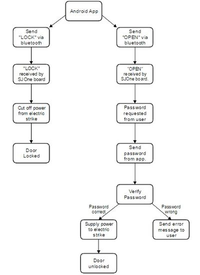
Door lock and unlock
- A connection between the bluetooth module and android app is established using UART2.
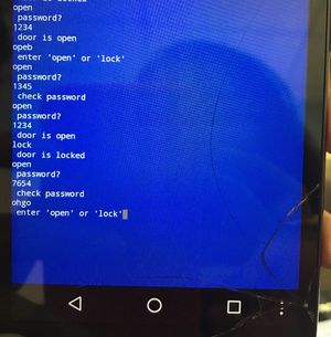
- A message "LOCK" or "OPEN" is sent from the app to the bluetooth module.
- If the bluetooth module receives a message "OPEN", it reverts to the app asking for a password.
- Now a password is sent from the app to the bluetooth module.
- The password is verified.
- If the password is a match, the SJOne board closes a switch between the electric door strike and 12V power supply.
- The door is unlocked.
- If the password do not match, an error message is sent to the app.
- If a message "LOCK" is received by the bluetooth module, The SJOne board cuts off power supply to the strike using the switch.
- The door is locked.
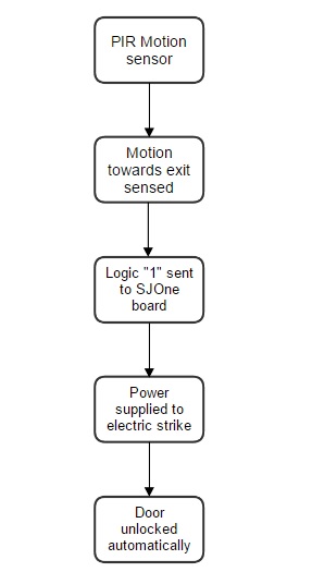
Automatic door opening by motion sensing
- The PIR motion sensor is connected to the SJOne board, which in turn is connected to the strike via a switch.
- When motion is detected on the inside of the door, the sensor send a logic "1" to the SJOne board.
- The SJOne board closes the switch between the electric strike and power supply.
- The door opens.
- When the sensor stops detecting motion, it sends a logic "0" to the board.
- The switch between the strike and power supply is opened.
- The door closes.
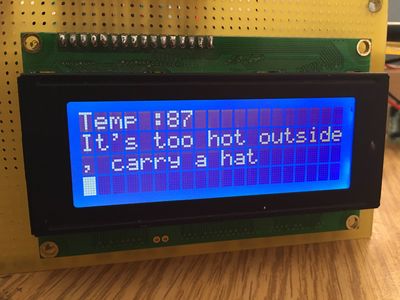
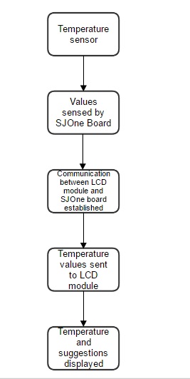
Temperature display at the entrance
- SJOne board has temperature sensors embedded in it.
- The outside temperature values are sensed, and sent to a LCD module.
- The LCD module is interfaced to the SJOne board using UART.
- The temperature values are displayed, along with appropriate and friendly suggestions to a person leaving the house!!
Software Design
Door Opening and closing
Algorithm used
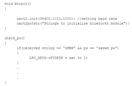
- Initialize bluetooth using bt_int().
- Use Uart2.gets()and Uart2.putstr() to receive and transmit characters respectively.
- Compare received string to "OPEN" or "LOCK".
- If password received, compare received password string with saved password.
- Make a GPIO pin on SJOne board as output.
- If "OPEN" is received, send 1 from GPIO pin to close the switch.
- Else if "LOCK" is received, send 0 from GPIO pin to open the switch.
Automatic Door Opening by motion sensing
Algorithm used
- Make a GPIO pin on SJOne board as input.
- Receive sensor output values on that pin.
- If pin reads "1", send "1" from the other GPIO pin to close the switch.
- Else if pin reads "0", send "0" from the other GPIO pin to open the switch.
Temperature Display on LCD
Algorithm used
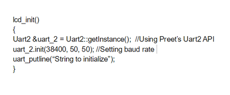
- Initilize LCD using lcd_init().
- Set baud rate using uart_init().
- Get temperature sensor values.
- Display text on LCD using uart_putline().
A binary semaphore was used to make sure that the door opens or locks(from the android app) only from one of the systems - either due to motion detected from the inside by the sensor, or by the command sent via bluetooth. Both the bluetooth task and the sensor task do a "semaphore give" when they want to lock/unlock the door, and the semaphore is taken by the "Lock"/"Unlock" task from wherever it comes first.
Testing & Technical Challenges
Issue #1
The electric door strike wasn't working. The piece was faulty, but it took us a while to realize that. Before figuring it out, a considerable amount of time was wasted under the impression that there was something wrong with our circuit.
Issue #2
The most basic circuit connection between any two hardware parts operating at two different voltage levels is a common ground. We forgot to connect a common ground between the SJOne board and the motion sensor and struggled for quite a bit before realizing it.
Issue #3
Insufficient amperage to the electric strike. Though the voltage we were supplying to the electric strike was 12V, it was not receiving enough current (200 mA) due to our incorrect selection of resistor values. As a result, the strike made a weak buzzing sound but didn't unlock.
Conclusion
This project was so much fun to work on. We also learnt a lot about interfacing sensors, LCD modules and bluetooth modules to embedded platforms. We faced our portion of challenges, and overcame them. Mainly, it sparked a greater interest in us about embedded development. Overall it was a great experience working on it.
Project Video
Project Source Code
https://gitlab.com/arpita.ramanath/SmartDoorLock.git
References
Acknowledgement
We would like to thank Professor Preet Kang for his constant guidance, support, encouragement and words of wisdom.
References Used
- Adafruit website: https://learn.adafruit.com/pir-passive-infrared-proximity-motion-sensor/overview
- https://www.sparkfun.com/datasheets/Components/LM7805.pdf
- Electric door strike connections: https://www.youtube.com/watch?v=K9fCKt6-b7o
