F22: xGameCreate
Contents
- 1 Grading Criteria
- 2 Whack-a-mole
- 2.1 Abtract
- 2.2 Objectives & Introduction
- 2.3 Team Members & Technical Responsibilities
- 2.4 Schedule
- 2.5 Materials List with cost
- 2.6 Design & Implementation
- 2.7 Game Logic
- 2.8 Testing & Technical Challenges
- 2.9 Conclusion
- 2.10 Project Video
- 2.11 Project Source Code
- 2.12 Acknowledgement
- 2.13 References
Grading Criteria
- How well is Software & Hardware Design described?
- How well can this report be used to reproduce this project?
- Code Quality
- Overall Report Quality:
- Software Block Diagrams
- Hardware Block Diagrams
- Schematic Quality
- Quality of technical challenges and solutions adopted.
Whack-a-mole
Abtract
Whac-a-Mole is a fun arcade game in which the player hits plastic moles with a hammer as soon as it appears out of their hole, to score points. We will be recreating the same old game with some modifications. Instead of plastic moles and a hammer, we will be using a LED Matrix to display mole-like characters and touch sensors to imitate the hammer. The scoring will be based on the no of moles you hit and how accurately you hit. We will be designing three levels and after each level, the difficulty of the game will rise.
Objectives & Introduction
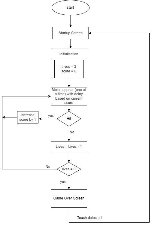
- The aim of the game is to hit as many moles as possible as they appear out of the holes
- There will be three lives and the speed and complexity of the game increase as the score goes up.
- If you miss a mole you lose a life
- Based on how many moles you hit your score will increase.
- The LED matrix is used to create the 12-mole-hole-like animation and the moles appear randomly in some holes.
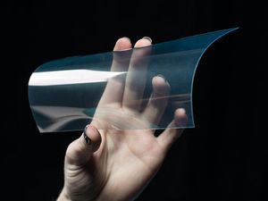
- ITO-coated PET is used for receiving the touch input (hitting the mole).
- A speaker is used to play background music, and sound clips when you hit a mole.
Team Members & Technical Responsibilities
- Karthigai Amutha Ezhilarasu
- Touch Sensor Driver Implementation
- Game logic design
- Hardware Integration
- Stephen Oneto
- Graphics Driver Implementation
- Game logic design
- Enclosure design and 3D printing
- Battery regulatory circuit design
- Yatish Koul
- MP3 Driver Implementation
- Integrating MP3 module with the Game
- Game logic design
Schedule
| Week# | Start Date | End Date | Task | Status |
|---|---|---|---|---|
| 1 |
|
|
|
|
| 2 |
|
|
|
|
| 3 |
|
|
|
|
| 4 |
|
|
|
|
| 5 |
|
|
|
|
| 6 |
|
|
|
|
| 7 |
|
|
|
|
| 8 |
|
|
|
|
| 9 |
|
|
|
|
Materials List with cost
| Part Name | Part Model & Source | Quantity | Cost Per Unit (USD) |
|---|---|---|---|
|
|
|
|
|
|
|
|
|
|
|
|
|
|
|
|
|
|
|
|
|
|
|
|
|
|
|
|
Design & Implementation
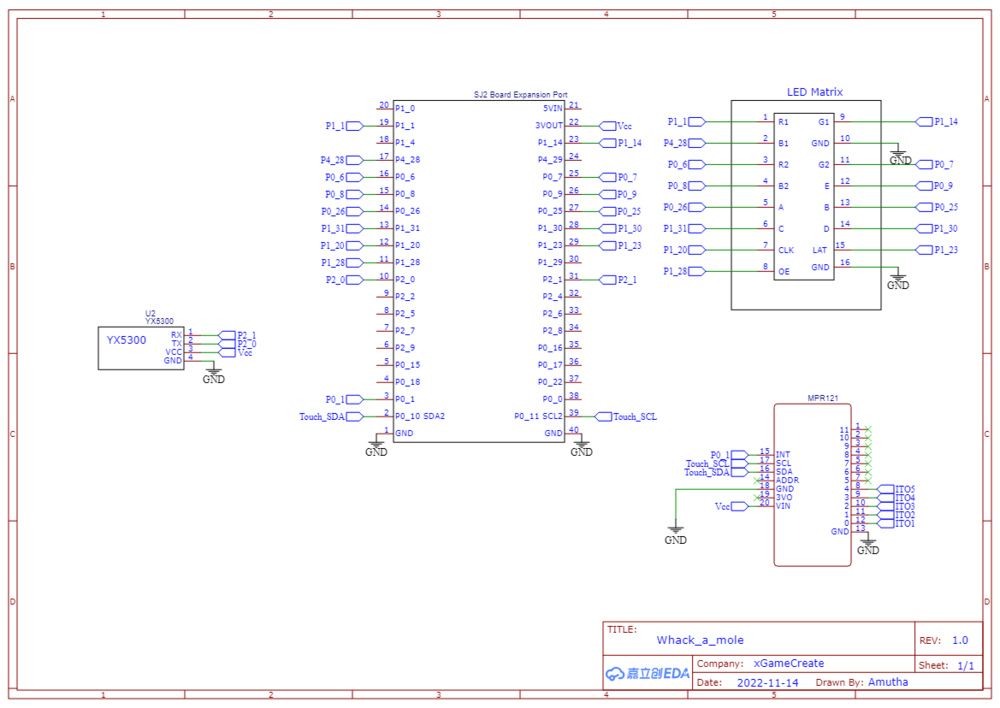
Schematic
Pin Configuration
-
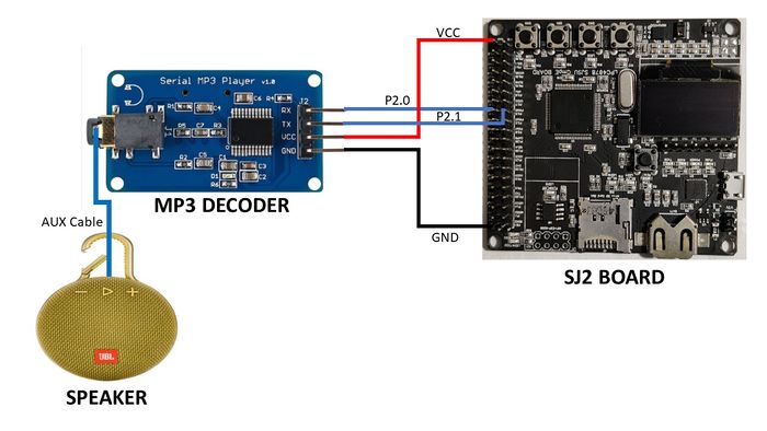
Pin# Description SJ-2 PIN R1 P0_0 G1 P0_1 B1 P2_2 R2 P2_4 G2 P2_5 B2 P2_6 A P2_7 B P2_8 C P2_9 D P0_16 E P0_15 OE P1_28 LATCH P1_29 CLK P0_17 MP3 Decoder RX UART Receive From MP3 Decoder P2_1 TX UART Send Command from SJ-2 Main Board P2_0 -
Pin# Controller Board Pin Configuration uC PIN TX P0_10 VCC VCC 3.3 P0_25 I/0 Pin P1_29
Hardware Design
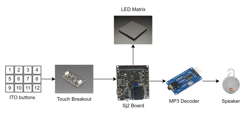
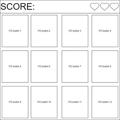
The system is built on the SJ2 development board. A 64*64 LED matrix, a touch breakout board, and an MP3 decoder are interfaced with the SJ2 board. The LED matrix screen has a top rectangle to display the score and lives. The remaining portion is divided into 12(4*3) rectangles depicting 12-mole holes. Each of the 12 holes is covered with an ITO-coated flexible transparent sheet. Each of the ITO sheets is connected to the touch sensor breakout board through wires. The system is designed to operate on a battery. The entire system is enclosed in a 3D-printed enclosure.
Capacitive Touch Breakout & ITO Sheets
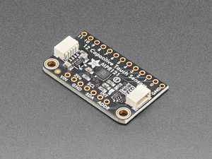
We used a MPR121 12-channel capacitive touch sensor breakout board. we can select one of 4 addresses with the ADDR pin, for a total of 48 capacitive touch pads via I2C. It handles all the filtering and can be configured for different levels of sensitivity. The MPR121 uses a constant DC current capacitance sensing scheme. The voltage measured on the input sensing node is inversely proportional to the capacitance. At the end of each charge circle, this voltage is sampled by an internal 10-bit ADC. The sampled data is then processed through several stages of digital filtering. The digital filtering process allows for good noise immunity in different environments. Once the electrode capacitance data is acquired, the electrode touch/release status is determined by comparing it to the capacitance baseline value. The capacitance baseline is tracked by MPR121 automatically based on the background capacitance variation. The baseline value is compared with the current immediate electrode data to determine if a touch or release has occurred.
We used ITO sheets to pass the finger touch input to the touch breakout board. ITO is Indium oxide doped with tin oxide which is electrical conductivity and optically transparent. The sheet we used is made of flexible PET coated with ITO on one side.
Hardware Design
The ITO sheets are cut into 12 rectangles. They are glued on top of the LED matrix with an approximate gap of one pixel in between to avoid contact. In order to protect the LED matrix from any accidental spoilage from the glue application we used a layer of transparent tape between the LED matrix and the ITO sheets. The 12 ITO buttons are connected to 12 pins of the touch sensor breakout board. When any of the pins detects a touch an interrupt will be generated and given to GPIO P0.1 of the SJ2 board.
Software Design
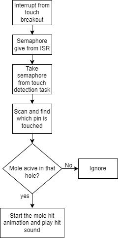
The interrupt from the touch breakout gives a semaphore from the ISR. On taking the semaphore the code will sequentially scan the status of all 12 pins to identify which pin is being touched. This communication between SJ2 and the touch status registers on the breakout board happens via the I2C bus. If the touched pin has an active mole, then the corresponding mole hit animation happens and a hit sound is played. If the touched pin is not associated with any of the current actives moles, that touch is simply ignored. Since we are ignoring the invalid touches, the touch debounce doesn't cause any problem with the game flow.
LED Matrix
Hardware Design
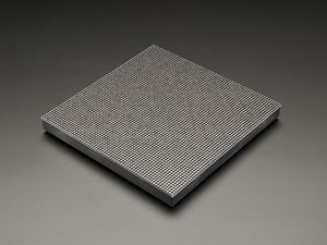
The LED matrix used was an Adafruit 64 x 64 matrix with a 2.5mm pitch. This pitch size provided a perfectly-sized screen that was neither too big nor too small. It featured a 14 pin interface (not including the 2 ground pins) which were interfaced to the SJ2 board through GPIO pins. To power the matrix, we repurposed the power cables included in the package and fashioned them to work with a standard 9V AC adapter.
Software Design
API
Software support for the matrix was done entirely through toggling GPIO pins. The most basic level of the API includes functions to set a single pixel, a row of pixels, and the entire board itself. We accomplish this by representing the matrix in memory as a 2D array. The array holds a special 3-bit enumeration type that corresponds to the various RGB values that the matrix is able to visually represent. A standard scan-based matrix lights a certain amount of rows at a time based on the scan rate using shift registers to hold the RGB values of each pixel and address lines to dictate which row(s) to light up. This process is made incredibly easy by simply traversing the 2D array row by row, pixel by pixel and pushing the values at each element to their corresponding RGB GPIO pins. A level above that in the API are the drawing helper functions. These functions provided functionality to draw/set pixels within the 2D array in the form of basic shapes (primarily lines). These functions were instrumental in developing the uppermost layer of our API the sprite layer. This layer uses the drawing helper functions to draw actual objects onto the screen such as alphanumeric characters and game art.
Tasks
From a task level, we had three main display tasks: the screen refresh task, the pattern modification task, and the mole animation task.
Refresh Task
The refresh task simply calls an API function to draw the entire board based on the 2D matrix array in memory, provides semaphores for the other tasks to run, and then sleeps for 8ms. 8ms was chosen through trial and error to give the best game performance to viewing experience ratio. One of the best features of the game is the incredibly smooth animations and this low refresh delay is the key factor in this.
Pattern modification task
The pattern modification task provided a way to make basic modifications to the screen in real-time. Using a global variable, other tasks are able to change the state of the screen by setting the variable to an enumeration value corresponding to a visual pattern. For example, every time a mole is struck the touch detection task sets the current pattern variable to the "Score" enumeration. The modification task picks this up, and increments the score on the screen.
Mole Animation Task
Similar to the modification task, this task performs modifications to the screen, but it is exclusively limited to animation of our mole characters. In essence, it receives a randomly generated 16-bit number from the mole pop task and generates animations for the moles corresponding the bits set in the received number. This is accomplished through a state machine keeping track which state the animation process is currently in at any given time and taking action based on changes in state. An example of this would be when a mole is struck by the player. When a mole is struck, an ISR generated by the touch sensor changes the state member of the structure used to maintain animation data. The next time this task runs, the mole hit state generates a blinking animation and then resets the state to idle.
System enclosure
MP3 Decoder
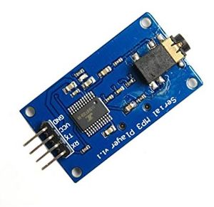
This module is a straightforward MP3 player that runs on the YX5300 high-quality MP3 audio chip. MP3 and WAV file formats with sampling rates of 8 kHz to 48 kHz are supported. The micro SD card used to store the audio files can be inserted because there is a TF card socket on the board. By sending commands to the module via the UART interface, the MCU can control the MP3 playback state by altering the volume, switching tracks, etc.
Hardware Design
The UART Tx, UART Rx, VCC, and GND pins are the 4 pins that the MP3 decoder module needs. The SJ2 board provided the module with the 3.3V it needed to start up. On the SJ2 board, UART1 pins have been set up so that commands can be sent to the decoder. This UART communication's baud rate is set at 9600 bps. Additionally, this decoder has a speaker-connected 3.5mm audio jack.
Software Design
In our project, the command we use plays the song by navigating to its index on the SD card. In our code, the function that sends this command is referred to as play music at index. We must first send the command [Select device] before we can send the instruction to play music at a specific index. The datasheet specifies that you should send "7E FF 06 09 00 00 02 EF" since Serial MP3 Player only accepts micro SD cards. Additionally, the function uart_polled_put on UART1 is being used to transmit the commands.
Game Logic
Show your software design. For example, if you are designing an MP3 Player, show the tasks that you are using, and what they are doing at a high level. Do not show the details of the code. For example, do not show exact code, but you may show psuedocode and fragments of code. Keep in mind that you are showing DESIGN of your software, not the inner workings of it.
This section includes implementation, but again, not the details, just the high level. For example, you can list the steps it takes to communicate over a sensor, or the steps needed to write a page of memory onto SPI Flash. You can include sub-sections for each of your component implementation.
Testing & Technical Challenges
Damaged ITO coating
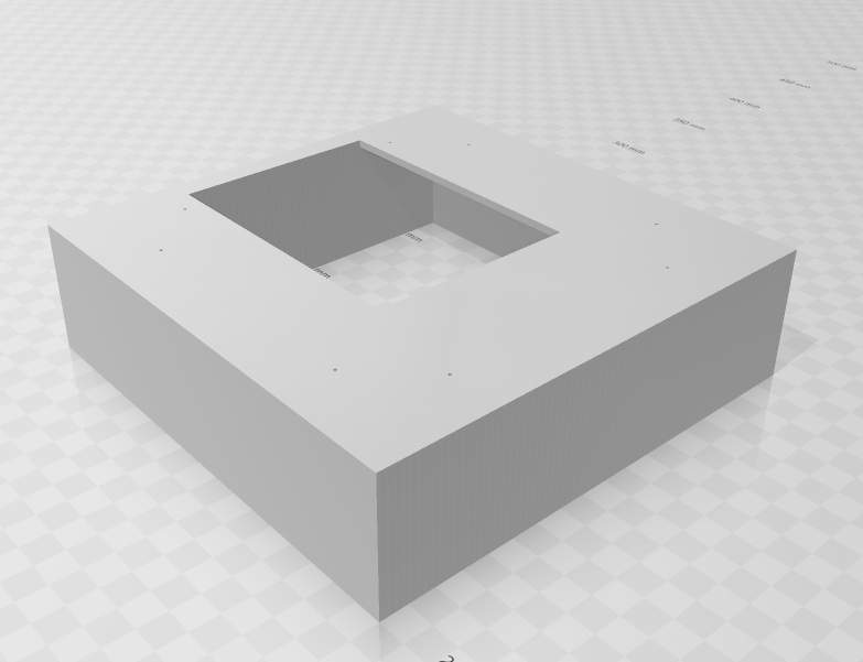
The main challenge we faced was with the ITO sheets. During the development phase, the ITO buttons we created worked perfectly. As we approach the first prototype demo, after putting all the hardware together we realized that the ITO sheets were not at all working. This happened because we were not careful in handling the ITO sheets. We used tape to keep the wires attached to the sheets. As we fixed and removed the tape so many times to get the perfect connectivity, we damaged the ITO coating. So, we used strips of aluminum foil during the remaining development phase and replaced them with the new ITO sheets just before the final demo. Also, keeping the wires in place is also challenging. So, we designed a 3D-printed enclosure to keep the wires intact and hide the visible wires on the top of the LED matrix.
LED blackout
Another problem we faced during the hardware integration is due to some loose connection of wires. The LED matrix worked fine sometimes but blacked out sometimes. We realized later that this happened because one of the wires was not soldered properly to the PCB.
Touch sensor breakout board short circuit
On the day that the project was due, one of our parts went up in smoke and short circuited to the point where it was unable to be used. This was likely the result of a power line coming into direct contact with a ground contact on the board or vice versa. Our design concept being a smaller, somewhat portable system, we designed our enclosure to have the bare minimum space required to fit all of the components. In doing this, our wiring had to be packed tightly which left plenty of room for error. This component is one of the main components used to drive our system and therefore, it was incredibly hard to simulate gameplay without it for the demo. For future endeavors, we will definitely consider making our packaging less needlessly compacted as well as potentially providing each component its own physical receptacle integrated into the casing, sectioning its contact points off from other components.
Conclusion
This project was a valuable teaching tool. Every module used for the project was effectively integrated, and we were able to reproduce our original game concept. During the project, we had a number of challenges, including difficulties starting the LED matrix driver, difficulties figuring out how to integrate touch sensing with so many game objects, difficulties creating and maintaining our complex game logic state machine, and much more. We were able to understand the real-world use of FreeRTOS while working on our project. We came to the conclusion that defining weekly goals and exceeding them could assist compartmentalize the project and eventually meet the desired outcome. This project improved our proficiency with embedded software and solidified our command of it.
Project Video
Upload a video of your project and post the link here.
Project Source Code
Acknowledgement
We would like to thank Professor Preetpal Kang for sharing his knowledge and insights with us during the course of the project.
References
List any references used in project.
