S15: Self-Balancing Robot
Contents
Project Title
Two Wheel Self-Balancing Robot
Abstract
The project is to build a two wheeled self-balancing robot. The robot is similar to a Segway machine but it uses sensors to alert the user when its path is blocked. The robot is also manually controlled using an Android phone via Bluetooth.
Objectives & Introduction
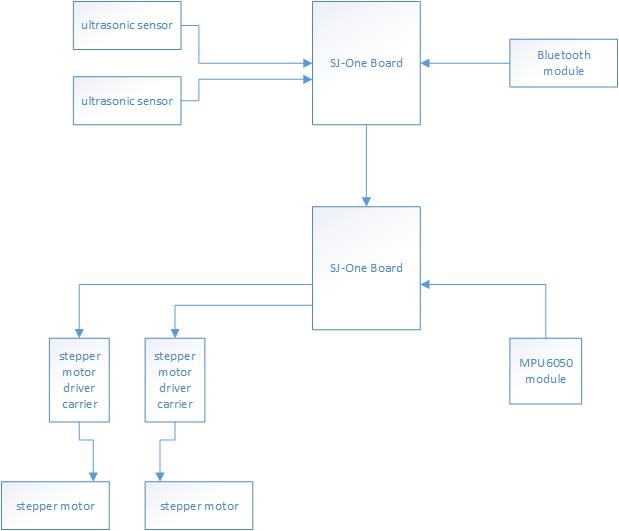
The purpose of this project is to design a two wheeled self-balancing robot. There are two parts to the system: motor controller and geographic controller. Each control system is implemented into different boards.
The motor control board is responsible for calibrating each motor to perform self-balancing and directional movements. In order for the robot to perform self-balancing, the motor control must implement a self-balancing algorithm which uses the input of an accelerometer and gyroscope module. The geographic control board provides directional movement the robot must execute such as turn left, go forward, stop, etc. The direction is mostly indicated by the user using an android phone via Bluetooth communication. The sensors are used to override user control for obstacle avoidance.
Team Members & Responsibilities
- Marvin Flores
- Stepper motor driver
- Accelerometer and gyroscope module driver
- Robot chassis
- Self balancing algorithm implementation
- Almon Otanes
- Bluetooth Communication
- Android App Development
- Sensor Interface
Schedule
| Week# | Date | Task | Actual |
|---|---|---|---|
| 1 | 4/3 | Build the Chassis of the robot | Completed: Yes. Problems Encountered: The battery is too heavy. The chassis needed to be reassembled a second time to fix the weight distribution problem. |
| 2 | 4/10 | Interface stepper motor driver carrier. | Completed:Yes Problems Encountered: We could not use the existing PWM driver, so we had to write our own to interface the stepper motor driver carrier |
| 3 | 4/17 | Bluetooth Communication Sensor Interface |
Completed: Yes |
| 4 | 4/24 | Interface Accelerometer and Gyroscope module. Android controller app |
Completed:Yes Problems Encountered: Had issue regarding I2C slave addressing. |
| 5 | 5/1 | Implement algorithm for self balancing Implement communications between two SJ-One boards Optimize drivers. |
Completed: Yes Problems Encountered: PID tuning. |
| 5 | 5/8 | Optimize algorithm implementation. Optimize drivers. |
Completed: No Problems Encountered: PID tuning. |
| 6 | 5/15 | Test. | Completed: No Problems Encountered: PID tuning. |
Parts List & Cost
| Quantity | Desctiption | Price |
|---|---|---|
| 2 | SJ-One development board | $80 ea |
| 2 | Stepper motor | $16.95 ea |
| 2 | Stepper motor driver carrier | $10.45 ea |
| 1 | MPU6050 Accelerometer + Gyroscope module | $4.47 |
| 1 | 9.2V battery pack | $16~ |
| 1 | Robot Chassis (standoffs, aluminum plates, screws, etc.) | $80~ |
| 1 | Bluetooth module | $27~ |
| 2 | Ultrasonic sensor module | $2~ ea |
| _______ | ||
| Estimated total | $350 |
Design & Implementation
Hardware Design
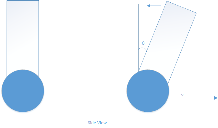
A self-balancing robot is an inverted-pendulum example problem. The idea is to keep the robot upright by driving the wheels towards the leaning angle theta.
I.e. when the robot is tilting forward, the wheels should be driven forward with a specific acceleration to counter the tilting. This will keep the robot in an upright position at all times.
The problem with this is that it is a very unstable system and a control algorithm must be used to stabilize it. For this project, the group decided to use a PID algorithm because of its simplicity
compared to other control algorithms. It is also readily available which is a plus considering the time we have to finish this project.
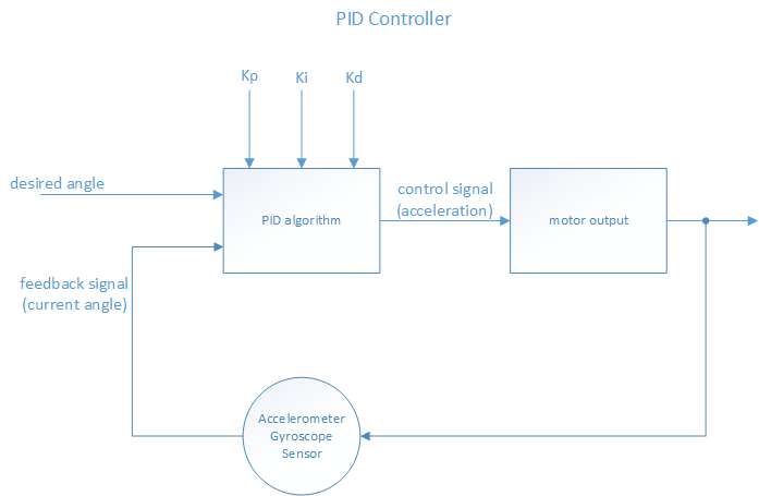
The PID controller is both software and hardware implementation. The angle reading from the MPU6050 module and the desired angle are fed to the PID algorithm — which calculates the error and outputs a control signal. The control signal is fed to the motorController which is responsible for driving the stepper motors.
The PID algorithm relies heavily on the three constant parameters: Kp Ki Kd, where Kp is the proportional constant, Ki is the integral constant, and Kd is the derivative constant.
The constants are multiplied with their respective terms P, I, and D terms.
The P term is responsible for calculating the proportional error or present error.
The I term is responsible for calculating the accumulation of the past errors.
The D term is responsible for calculating the prediction of future errors based on DT (rate of change).
By summing up these three terms, the PID controller is able to output a control signal that drives the system towards the target output (desired angle).
Hardware Interface
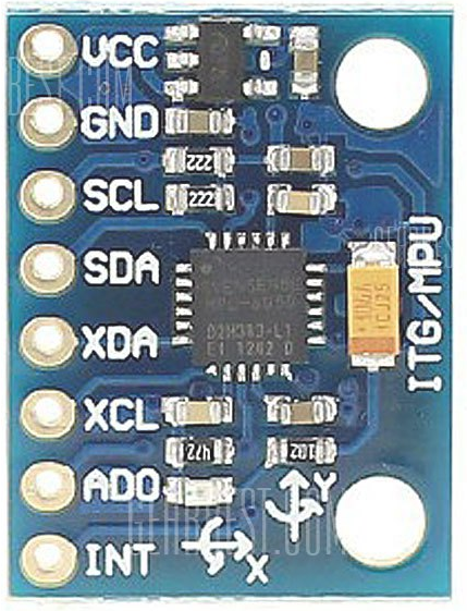
MPU6050
3-axis accelerometer, 3-axis gyroscope MODULE
The group used this module because the 3-axis accelerometer alone can't handle the complexity of the self-balancing robot. This module outputs raw data which need to be filtered in order to obtain the correct angle measurement
The group used Kalman filter to obtain the angle measurement. The source code for Kalman filter was obtained online to save time implementing it. The code can be found here: https://github.com/TKJElectronics/KalmanFilter/blob/master/examples/MPU6050/MPU6050.ino
This module uses I2C protocol for communication. The group needed to write their own driver for the MPU6050 in able to interface the module to the SJ-ONE board.
Only 4 pins are used in this module: Vcc, Gnd, SCL, SDA where SCL is the clock signal and SDA is the data signal.
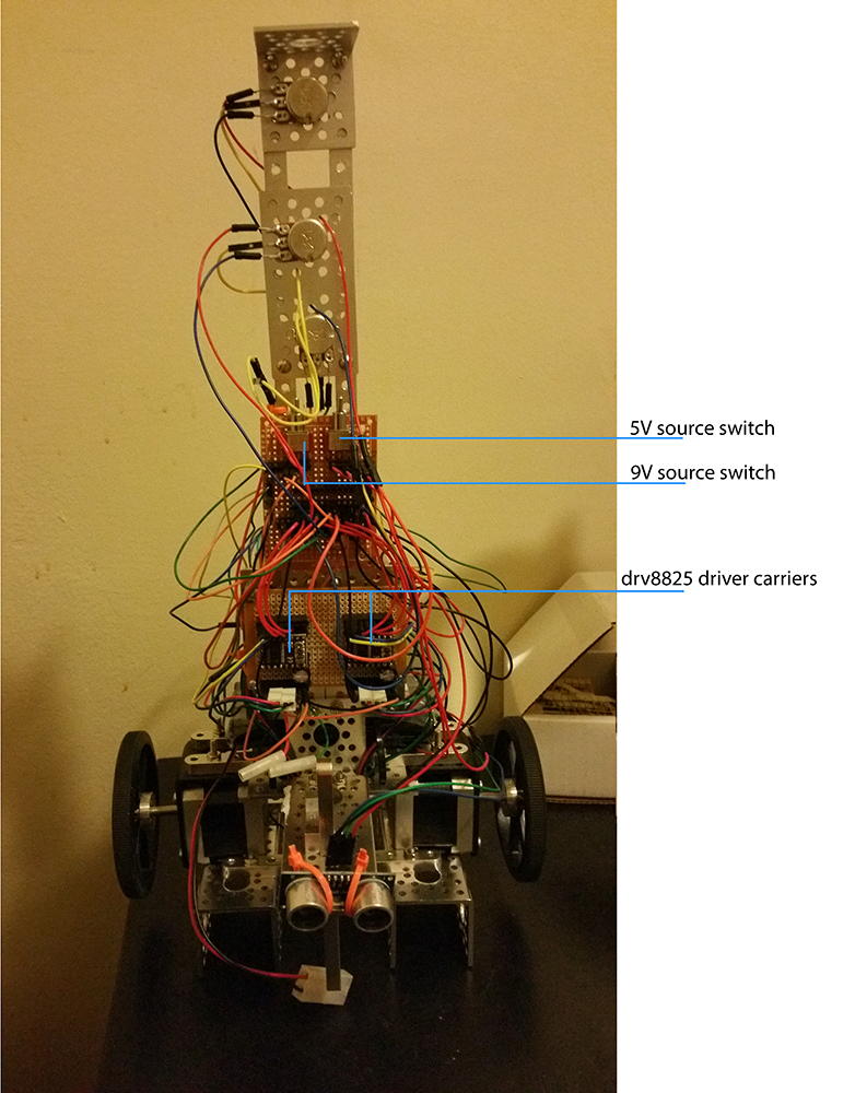
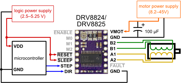
This module was used to control one bipolar stepper motor, so a total of two drv8825 driver carriers were used for this project.
This driver carrier simplifies the method of controlling the stepper motors — it only needs a step frequency and a direction signal to control a single bipolar stepper motor
The group wrote their own driver to produce a step frequency and direction signal. This implementation took a while to finish because the group needed to understand how the PWM Motor Control is implemented on LPC1758 mcu
This interface uses two PWM pins for step frequencies, and two regular I/O pins for direction signal.
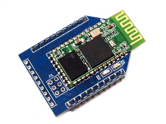
This module was used to create a communication between an android phone (via an app) and the robot. The WLS04051P bluetooth module contains an ATMEGA 168 which is used from reprogramming the module. It is also compatible to the XBee socket of the SJOne Board. The XBee Socket can be set up to use either UART2 or UART3 using an on board switch located in the socket. The Tx and Rx goes through which UART port is set. The module also have an command set with it. The command set is used for initializing the module settings. The commands are used by sending them through the UART port. The module contains two LEDs (blue and red) which indicates its status. The LEDs alternate between red and blue when it is inquiring for devices. Once it is paired with a device, the blue LED will start flashing once per two seconds.
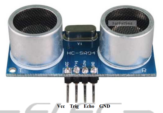
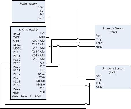
This module was used for the collision avoidance function of the robot. An ultrasonic sensor was placed at the front and back of the robot. When it detects an object about 10cm from it, the direction is overridden and the robot is stopped. The module requires Vcc, GND, and two GPIO pins. The GPIO pins are used for Trig and Echo pins of the module. The Trig pin is an input to the module which serves as a request from the CPU. The Echo pin turns high after some time with the Trig pin is setup. It will remain high until the signal from the module bounces back from an object infront of it.
Software Design
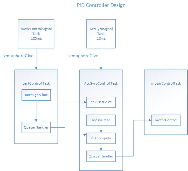
The group tried to make the software design as simple as possible. There are two Signal tasks that activates their respective 'worker' tasks. The worker tasks only activates when they receive a semaphore signal.
The moveControlSignal task is responsible for sending a signal every 100ms to the uartControl task — which reads the uart data register. The uartControl task then sends the read data to the AccGyroControl task.
The AccGyroSignal task is responsible for sending a signal every 10ms to the AccGyroControl task.
The AccGyroControl task is responsible for the sensor reading and computation of the PID controller. This task is also responsible for sending the output of the PID controller to motorControl task.
The motorControl task is responsible for driving the motors.
The responsibility of one of the two boards used was to provide the direction to the motor control. This board incorporates the bluetooth module and the ultrasonic sensor together. The robot can be manually controlled using an app from an android device. The provided direction is transmitted to the SJOne board through bluetooth communication via the bluetooth module. The robot was also designed with collision avoidance. This is where the ultrasonic sensors were used. When an obstacle is detected by the sensors, it overrides whichever direction is given by the user and tells the robot to stop.
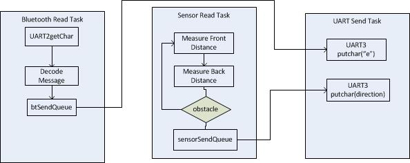
Three tasks were created for this portion of the software design as shown in Fig. 11. The bluetooth task reads two characters from the UART. Those two characters are decoded to find the direction. The app that was used to control the robot provides five controls: forward, reverse, left, right, and stop. Those exact words are transmitted through the UART for the specified direction. Due to the varying message lengths, only two characters are read at a time. Once the direction is decoded, the rest of the message is read. The direction is then indicated using one character such that 'a' is forward, 'b' is reverse, 'c' is left, 'd' is right, and 'e' is stop. The one character direction is sent to the UART_send_task using a shared queue.
The sensor read task reads the distance of the front and back sensors. If any of the two sensors shows an obstacle or an object within 10 cm of the robot, an integer is sent to the UART_send_task using a shared queue. Otherwise, the sensor read task does not do anything and loops back.
The purpose of the UART_send_task is to send the direction to the other board using UART interface. The data it chooses to send is indicated by the shared queues from the other two tasks. If the shared queue with the sensor is not empty, this task sends a the character 'e' (stop). Else, if the shared queue with the bluetooth task is not empty, then it sends the direction. Otherwise, the task does not do anything.
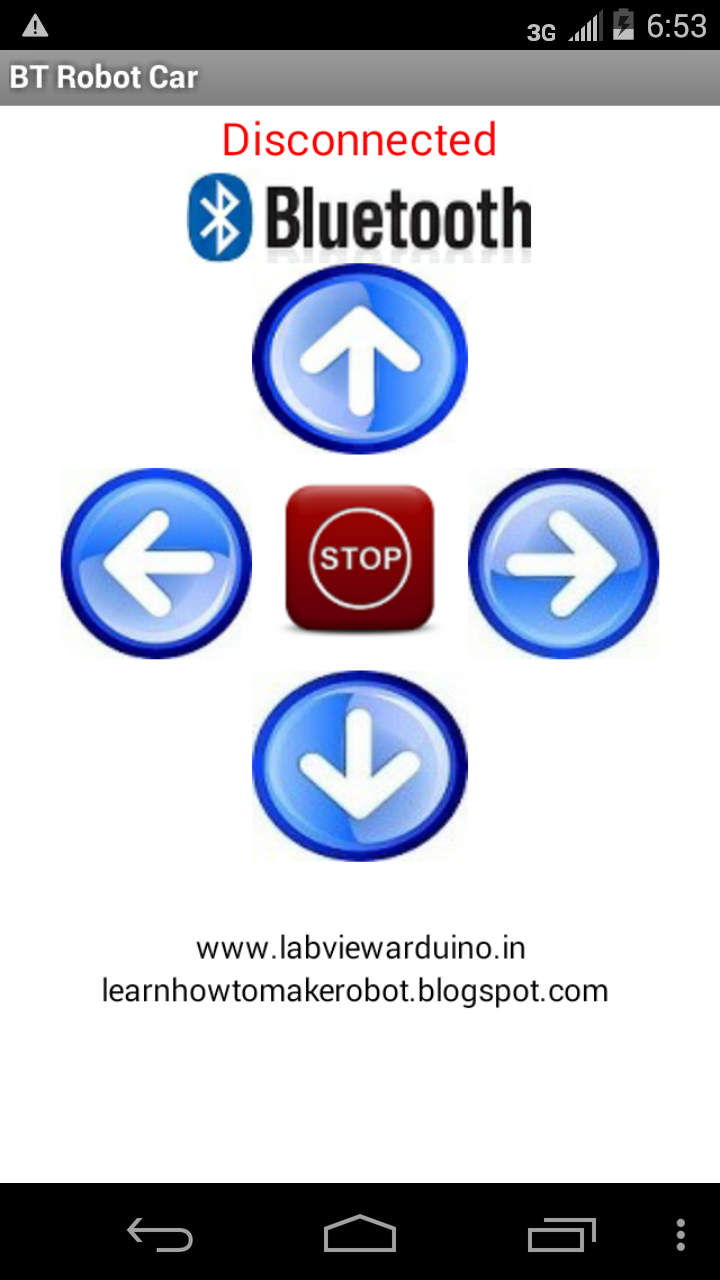
The android app features four directional control and a stop button in the middle. When the bluetooth button is pressed, it scans for nearby devices it can pair to. This app was taken from http://www.instructables.com/id/How-to-make-a-voice-control-direction-control-remo/.
Implementation
PID controller driver
Take target angle
Take input angle
Take constant parameters
Take rate of change
Calculate output based on the above inputs
Return output value to the caller
MotorControl driver
Initialize output pins (PWM and I/O pins)
read output of PID controller
set direction (forward or backward)
limit acceleration
calculate speed
convert speed data to step frequency
Use the new step frequency to drive the motors
Accelerometer and Gyroscope driver
Initialize module
set offsets
set initial setpoint (should be close to zero degrees)
read data
call Kalman filter function to get accurate angle measurement
output the filtered angle
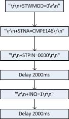
Bluetooth Module driver
Initialize UART to 38400 baud rate
Delay 1000ms
send "\r\n+STWMOD=0\r\n"
send "\r\n+STNA=CMPE146\r\n"
send "\r\n +STPIN=0000\r\n");
delay 2000ms
send "\r\n+INQ=1\r\n"
delay 2000ms
Ultrasonic Sensor Module driver
Trig output = 1
Delay 10us
Trig output = 0
Wait for Echo to go to high
Save system time in us as start time
Wait for Echo to go to low
Save system time in us as end time
Calculate distance = (end time - start time)/58.82 (58.82 is specific to calculating distance in cm)
Testing & Technical Challenges
The testing of the balancing mostly relied on the PID controller. This of course assumed that the accelerometer+gyroscope sensor provides accurate angle readings.
The PID controller has three constant parameters, which are needed to be tuned perfectly to be able to balance the robot.
The testing of this project was the hardest part of all. Since the system is an unstable system and a PID controller was used to stabilize it, the success
of the project depends on how well the PID controller is implemented. Unfortunately, the group failed to make the robot to balance because of lack of background
regarding PID controllers. The PID controller is very popular because of its simplicity but its implementation is tougher than it looks. The issues below will
surely help future students that want to build their own self-balancing robot.
My Issue #1
Stepper Motors. Stepper motors have high torque and can be controlled precisely (e.g. 1/4 revolution, 350 steps, etc) but writing own drivers for the stepping frequency is time consuming. The reader should avoid using stepper motors unless the reader has access to drivers or the reader has experience using stepper motors.
My Issue #2
Accelerometer + Gyroscope: Even though MPU6050 has a lot of examples online, most of them are written in Arduino. This means that the codes available online are not readily transferable to the SJ-One board. A thorough understanding of the module is needed to be able to implement it correctly. This module also has undocumented functionalities that can't be access easily; moreover, these hidden functionalities are only available in Arduino. This means that to implement it to the SJ-One board, one needs to convert an Arduino code into C code which will surely take a lot of time.
The group suggests that the reader should carefully choose a sensor module.
My Issue #3
PID controller: Besides how people view this as a very simple control algorithm, it is very hard to implement. The reader should research ahead of time about the PID controller.
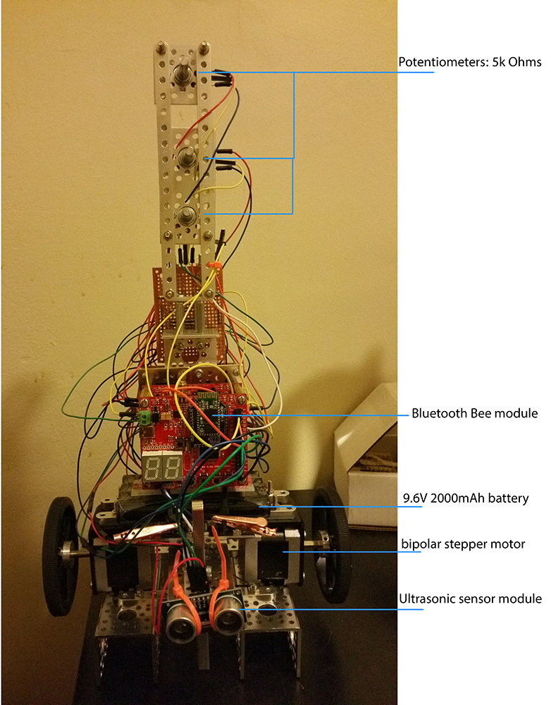
PID controller constants: These three constants are needed to be tuned perfectly, thus the group suggests that these three parameters should be modifiable in real time. The group realized this too late that's why a lot of time was wasted just by changing the constants. Three 5k Ohms potentiometer connected to ADC pins was the perfect solution to this problem.
My Issue #4
Tuning: since this is the hardest part of the project, a lot of time should be devoted in tuning the controller. The group spent a total of 4 weeks just tuning the PID and still failed to make the robot balance. This problem is a combination of the PID controller implementation and the motor driver implementation. These two should be implemented properly in order to make the tuning possible.
Conclusion
Even though a PID controller is popular because of its simplicity, the implementation of it is not so simple. The three constants that are used need to be tuned perfectly in able to obtain the desired output. The problem with this is that a lot of time is needed to tune these parameters perfectly. The lack of experience about PID controllers and the necessary preparation needed (e.g. interface sensor module, writing motor drivers, etc.) made this project incredibly difficult for the group.
This project pushed the group to their limits. Although the group failed to make the robot balance, the group learned a lot regarding the behavior of unstable systems and what are the possible solutions to stabilize them. The group also learned a lot about the PID algorithm and its implementation. The group believes that given more time, a successful PID controller implementation is possible.
Project Video
Upload a video of your project and post the link here.
Project Source Code
References
Acknowledgement
Any acknowledgement that you may wish to provide can be included here.
References Used
List any references used in project.
http://www.geekmomprojects.com/gyroscopes-and-accelerometers-on-a-chip/
https://solenerotech1.wordpress.com/2013/10/10/how-to-combine-data-from-gyro-and-accel/
http://www.instructables.com/id/Self-Balancing-Robot/
http://hyperphysics.phy-astr.gsu.edu/hbase/rotq.html
http://jjrobots.com/b-robot/
http://letsmakerobots.com/node/38610
http://home.iitk.ac.in/~vipgupta/self-balancing-bot
http://ww1.microchip.com/downloads/en/AppNotes/00964A.pdf
