F15: ThunderBird
Contents
- 1 ThunderBird : Self Driving Car
- 2 Abstract
- 3 Objectives & Introduction
- 4 Schedule
- 5 Parts List & Cost
- 6 Design & Implementation
- 7 Sensor Controller
- 8 Motor and I/O Controllers
- 9 GPS Controller
- 10 Master Controller
- 11 Bluetooth Control and Android application
- 12 Testing & Technical Challenges
- 13 Conclusion
- 14 References
ThunderBird : Self Driving Car
Abstract
ThunderBird is a 1/10 2 WD electric short self-driving truck. The truck is equipped with sensors to detect obstacles, GPS for getting directions, Compass for the truck's orientation, Bluetooth for communicating with the android device and LCD for displaying the sensor values on screen. The modules are interfaced using 5 SJ One boards which features a Cortex-M3 LPC1758. CAN bus is used for communicating between the modules. Android device is used to enter the destination coordinates through bluetooth. When the sensors detect obstacles, it signals the motors to drive the car accordingly.
Objectives & Introduction
Team Members & Responsibilities
- Master Controller and Android application
- Sravani Aitha
- Vishnu Vardhana Reddy Mandalapu
- James Sushanth Anandraj
- Athavan Kanagasabapathy
- Motors and I/O
- Dheeraj Dake
- Akhil Bhargav Josyabhatla
- Sensors
- Nitesh Jain
- Rajashree Kambli
- GPS
- Rishit Borad
- Ravi Vanjara
Schedule
Motor and I/O Schedule
| Sl. No | Start Date | End Date | Task | Status | Actual Completion Date |
|---|---|---|---|---|---|
| 1 | 10/6/2015 | 10/13/2015 | Determining the ESC initialization sequence | Completed | 10/11/15 |
| 2 | 10/13/2015 | 10/20/2015 | Testing the Servo and DC motor using SJ One board PWM's | Completed | 10/16/2015 |
| 3 | 10/20/2015 | 10/27/2015 | Design motor control using messages from the CAN bus | ||
| 4 | 10/27/2015 | 11/3/2015 | Implement code to accept messages from other modules over CAN bus and display it on the LCD | ||
| 5 | 11/3/2015 | 11/10/2015 | Update motor speeds on the LCD in real time | ||
| 6 | 11/10/2015 | 11/17/2015 | Interface I/O and motor modules with master controller and establish communication | ||
| 7 | 11/17/2015 | 11/24/2015 | Fine turning motors for precise control | ||
| 8 | 11/24/2015 | 12/01/2015 | Fine tuning (buffer) | ||
| 9 | 12/01/2015 | 12/08/2015 | Testing and debugging |
Geographical Position Controller Schedule
| Sl. No | Start Date | End Date | Task | Status | Actual Completion Date |
|---|---|---|---|---|---|
| 1 | 10/6/2015 | 10/13/2015 | Research & order GPS module | Completed | 10/8/2015 |
| 2 | 10/13/2015 | 10/20/2015 | Interface GPS using I2C with SJOne board | Ongoing | |
| 3 | 10/20/2015 | 10/27/2015 | Interface Compass with SJOne board | ||
| 4 | 10/27/2015 | 11/3/2015 | Calibrate Compass and GPS | ||
| 5 | 11/3/2015 | 11/10/2015 | Parse raw data and create meaningful data | ||
| 6 | 11/10/2015 | 11/17/2015 | Implement CAN communication with SJOne board | ||
| 7 | 11/17/2015 | 11/24/2015 | Test and debug GPS & Compass locally | ||
| 8 | 11/24/2015 | 12/01/2015 | Integrate GPS/Compass module with Master board | ||
| 9 | 12/01/2015 | 12/08/2015 | Implement routing algorithm for Car | ||
| 10 | 12/08/2015 | 12/15/2015 | Test and Debug GPS/Compass integration with master |
Sensor Controller Schedule
| Sl. No | Start Date | End Date | Task | Status | Actual Completion Date |
|---|---|---|---|---|---|
| 1 | 10/5/2015 | 10/11/2015 | Finalize and order the sensors | Completed | 10/11/2015 |
| 2 | 10/12/2015 | 10/18/2015 | Wire the sensors and write a sample test code to check the sensors. | Ongoing | |
| 3 | 10/19/2015 | 11/01/2015 | Transfer the sensor data to master controller via can bus. | ||
| 4 | 11/2/2015 | 11/9/2015 | Implement and integrate the code for all the sensors. | ||
| 5 | 11/2/2015 | 11/15/2015 | Test and Debug the integrated module. | ||
| 6 | 11/16/2015 | 11/29/2015 | Collaborate with the other module teams to make sure that the sensors are in working condition. | ||
| 7 | 11/30/2015 | 12/06/2015 | Test for stability of sensors and report. | ||
| 8 | 12/07/2015 | 12/13/2015 | Prepare for Demo. |
Master controller and android controller Schedule
| Sl. No | Start Date | End Date | Task | Status | Actual Completion Date |
|---|---|---|---|---|---|
| 1 | 10/6/2015 | 10/13/2015 | Car purchase ,dismantle and setup for project | Completed | 10/8/2015 |
| 2 | 10/13/2015 | 10/20/2015 | Can setup components purchase, Can bus design and soldering | Ongoing | |
| 3 | 10/20/2015 | 10/27/2015 | Basic Can communication testing by sending and receiving data and can msg specification for all controllers and messages. | ||
| 4 | 10/27/2015 | 11/3/2015 | Development and implementation of Algorithm for driving car and obstacle avoidance. | ||
| 5 | 11/3/2015 | 11/10/2015 | Interface bt dongle with sjone board and android device and test with commands | ||
| 6 | 11/10/2015 | 11/17/2015 | Develop Android GUI and application to interact with car using bluetooth. Implement all necessary commands on sjone board for communication with android device. Interface with Motor and IO Controller. | ||
| 7 | 11/17/2015 | 11/24/2015 | Test and debug Master algorithm and Android interface locally and with Motor controller interfaced by providing predetermined directional commands. | ||
| 8 | 11/24/2015 | 12/01/2015 | Integrate Master Board with all boards and implement heartbeat protocol. | ||
| 9 | 12/01/2015 | 12/08/2015 | Test run 1 with all boards integrated and with all planned features developed. | ||
| 10 | 12/08/2015 | 12/15/2015 | Test run 2 after solving issues found in test run 1. |
Parts List & Cost
| S.R. | Description | Manufacturer | Part Number | Qty | Total Cost |
|---|---|---|---|---|---|
| 1 | SJOne Board | - | - | 5 | $400.00 |
| 2 | RC Car | Furry Arrma - 2 Wheel Drive - 1/10 | - | 1 | $185.00 |
| 3 | Ultrasonic Sensor | LV-MaxSonar - EZ1 | MB1010 | 5 | $140.00 |
| 4 | 1.8 Color TFT LCD display with MicroSD Card Breakout | Adafruit | ST7735R | 1 | $19.95 |
| 5 | SparkFun Venus GPS with SMA Connector | Sparkfun | GPS-11058 | 1 | $49.95 |
| 6 | Triple-axis Magnetometer (Compass) Board | Adafruit | HMC5883L | 1 | $9.95 |
| 7 | CAN Transceiver (Free Samples) | Microchip | MCP2551 | 6 | $0.00 |
| Total (Including Shipping and Taxes | ---- |
Design & Implementation
The design section can go over your hardware and software design. Organize this section using sub-sections that go over your design and implementation.
Hardware Design
Discuss your hardware design here. Show detailed schematics, and the interface here.
Hardware Interface
In this section, you can describe how your hardware communicates, such as which BUSes used. You can discuss your driver implementation here, such that the Software Design section is isolated to talk about high level workings rather than inner working of your project.
Software Design
Show your software design. For example, if you are designing an MP3 Player, show the tasks that you are using, and what they are doing at a high level. Do not show the details of the code. For example, do not show exact code, but you may show psuedocode and fragments of code. Keep in mind that you are showing DESIGN of your software, not the inner workings of it.
Implementation
This section includes implementation, but again, not the details, just the high level. For example, you can list the steps it takes to communicate over a sensor, or the steps needed to write a page of memory onto SPI Flash. You can include sub-sections for each of your component implementation.
Sensor Controller
Motor and I/O Controllers
ThunderBird is a 2 WD truck. It is equipped with a ARRMA BLX brushless DC motor connected to an BLX80 ESC(Electronic Speed Control). The ESC drives the DC motor according to the PWM(Pulse Width Modulation) signal. The truck's front wheels are connected to a waterproof ADS-7M Metal Geared Steering Servo. The servo and the DC motor are controlled using the PWM pins of the SJOne board.
Pulse Width Modulation - Controlling DC and Servo motors
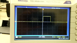
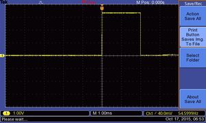
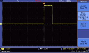
Pulse width modulation is a technique which is used to encode the analog signal into a pulsating signal. The signal is represented as a series of pulses. This signal can be easily generated using the pwm pins of the SJOne board. The ESC is initialized upon passing a PWM signal which is sent by the RF module on the truck. The type of signal is observed by hooking the PWM pin to the digital oscilloscope. The initialization signal is shown in figure 1. A resolution of 1ms is set on the oscilloscope. The PWM signal has a width of 1.5 ms. This signal initializes the ESC. Once the ESC's are initialized, the motors require a signal to accelerate and decelerate. The type of signals for moving the motor forward and backward are realized by hooking the output pin of the RF module to the digital oscilloscope. The forward and backward pwm signals at full throttle are shown in figures 2 and 3 respectively. The respective pwm signal pulses for moving the motors forward and backward are shown below.
- Acceleration PWM signal
- Forward full throttle - 2 ms
- Forward medium throttle - 1.8 ms
- Neutral - 1.5 ms
- Reverse PWM signal
- Reverse full throttle - 1 ms
- Reverse medium throttle - 1.2 ms
- Neutral - 1.5 ms
The PWM value to be set is determined from these calculations:
- PWM is a percentage of the signal frequency
- The signal is of 50 Hz i.e. 20 ms duration
- A 10% of the signal value gives a duration of 2 ms - 10/100 * 20 = 2 ms
The respective percentages for all the signal were calculated and the PWM signals were generated using the PWM.set function. The generated pulses from the SJOne PWM pin is passed to the ESC for initialization and controlling the DC motor. The ESC has 3 connections - Vcc, GND and PWM. SJOne board's GND and PWM are connected to the ESC. The Vcc is supplied from the battery pack.
A sample code demonstrating the PWM signals is written and the motors were controlled using the on-board SJOne switches. Click here for the demo.
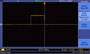
The servo motor channel in the RF module is hooked to the digital oscilloscope to determine the initial sequence. It is observed that when the RF transmitter is switched on, the RC remote sends a pwm signal which resets the servo to its starting position. This PWM signal re-centers the truck's wheels. The signal is realized by hooking the data pin from the first channel of the RF module to the digital oscilloscope. The PWM signal is shown in figure 4. The signal is having a pulse of 1.6 ms. The steering on the RC is moved left and right to determine the PWM signals. The signal values were noted from the oscilloscope. The values are tabulated below.
- Steering PWM signal
- Steer full right - 2 ms
- Steer full left - 1 ms
- Steer center - 1.6 ms
A PWM signal having a pulse width between 1.6 ms to 2 ms is used to control the steering towards right precisely. Similarly, a PWM signal having a pulse width between 1 ms to 1.6 ms is used to control the steering towards left precisely. The servo has 3 connections - Vcc, GND and PWM. The servo motor is not connected to a ESC. It doesn't get any voltage if it is not connected to the RF module. The servo motor operates at 6V. For testing, the Vcc of the servo motor is connected to the RF module. The GND from the RF module is made common with the GND from SJOne board. The PWN signal is given as an input from the SJOne board. The PWM signal values were calculated using the procedure shown above. The respective PWM signals were then sent to the servo motor using the PWM pin on the SJOne board for steering the truck.
The on-board switches on the SJOne board are used to steer the truck left and right. A sample code demonstrating this functionality is written and tested. Click here for the demo.
GPS Controller
Master Controller
Bluetooth Control and Android application
Testing & Technical Challenges
Describe the challenges of your project. What advise would you give yourself or someone else if your project can be started from scratch again? Make a smooth transition to testing section and described what it took to test your project.
Include sub-sections that list out a problem and solution, such as:
My Issue #1
Discuss the issue and resolution.
Conclusion
Conclude your project here. You can recap your testing and problems. You should address the "so what" part here to indicate what you ultimately learnt from this project. How has this project increased your knowledge?
Project Video
Upload a video of your project and post the link here.
Project Source Code
References
Acknowledgement
Any acknowledgement that you may wish to provide can be included here.
References Used
List any references used in project.
Appendix
You can list the references you used.


