F17: Optimus
Contents
- 1 Optimus
- 2 Abstract
- 3 Objectives & Introduction
- 4 Team Members & Responsibilities
- 5 Schedule
- 6 Parts List & Cost
- 7 CAN Communication
- 8 DBC File
- 9 Android and Communication Bridge
- 10 Geographical Controller
- 11 Sensor and I/O
- 12 Motor Controller
- 13 Master Controller
- 14 Common Technical Challenges
- 15 Conclusion
- 16 References
Optimus
Optimus - Self Navigating R/C Car powered by SJOne(LPC1758) micro controller.
Abstract
[[|thumb|centre|700px|System Diagram]]
Objectives & Introduction
Team Members & Responsibilities
- Android and Communication Bridge:[[|233px|right]]
- [ Parimal]
- [ Parimal]
- Geographical Controller:
- [ Sneha]
- [ Sarvesh]
- [ Sneha]
- Master Controller:
- [ Unnikrishnan]
- [ Revathy]
- [ Kripanand]
- Motor Controller
- [ Unnikrishnan]
- [ Rajul]
- [ Unnikrishnan]
- Sensor and I/O Controller:
- [ Sushma]
- [ Supradeep]
- [ Harshitha]
- [ Sushma]
Schedule
Legend:
Major Feature milestone , CAN Master Controller , Sensor & IO Controller , Android Controller, Motor Controller , Geo , Testing, Ble controller, Team Goal
| Week# | Date | Planned Task | Actual | Status |
|---|---|---|---|---|
| 1 | 9/23/2017 |
|
|
Complete. |
| 2 | 9/30/2017 |
|
|
Complete |
| 3 | 10/14/2017 |
|
|
Complete |
| 4 | 10/21/2017 |
|
|
complete |
| 5 | 10/28/2017 |
|
|
Complete |
| 6 | 11/07/2017 |
|
|
Complete |
| 7 | 11/14/2017 |
|
|
Complete. |
| 8 | 11/21/2017 |
|
|
Complete. |
| 9 | 11/28/2017 |
|
|
Complete. |
| 10 | 12/5/2017 |
|
|
Complete |
| 11 | 12/12/2017 |
|
|
On Track |
Parts List & Cost
The Project bill of materials is as listed in the table below.
| Item# | Part Description | Vendor | Qty | Cost |
|---|---|---|---|---|
| 1 | SJ One Board (LPC 1758) | From Preet | 6 | $480 |
| 2 | [1] | Prof. Kaikai Liu provided | 1 | $0 |
| 3 | Accelerometer/Magnetometer LSM303 | Adafruit | 2 | $40.00 |
| 4 | Bluetooth Module | Sparkfun | 1 | $34.95 |
| 5 | CAN Transceivers | From ebay. | 15 | $51 |
| 6 | Battery Pack | From Sheldon Hobbist | 1 | $49.99 |
| 7 | RP Lidar | 5 | $400 | |
| 8 | LED $ Digit Display | From Preet | 1 | $0 |
| 9 | GPS Module | From Adafruit | 1 | $43.34 |
| 10 | General Components | From Amazon | - | $ |
| 11 | RPM Sensor | From traxxas | 1 | $20 |
| 12 | PCB | 1 | $10.66 | |
| 13 | Acrylic Board | From Amazon | 1 | $12.53 |
| 14 | PCAN dongle | From Preet | 1 | $0 |
| 15 | Power Bank | From Amazon | 1 | $41.50 |
| 16 | PCB Manufacturing | From PCB Way | 5 | $70 |
CAN Communication
System Nodes : MASTER , MOTOR , BLE , SENSOR , GEO
| SNo. | Message ID | Message from Source Node | Receivers |
|---|---|---|---|
| Master Controller Message | |||
| 1 | 2 | System Start command to start motor | Motor |
| 2 | 17 | Target Speed-Steer Signal to Motor | Motor |
| 3 | 194 | Telemetry Message to Display it on Android | BLE |
| Sensor Controller Message | |||
| 4 | 3 | Lidar Detections of obstacles in 360 degree grouped as sectors | Master,BLE |
| 5 | 36 | Heartbeat | Master |
| Geo Controller Message | |||
| 4 | 195 | Compass, Destination Reached flag, Checkpoint id signals | Master,BLE |
| 5 | 4 | Turning Angle | Master,BLE |
| 5 | 4 | Heartbeat | Master |
| Bluetooth Bridge Controller Message | |||
| 4 | 38 | Heartbeat | Master |
| 5 | 213 | Checkpoint Count from AndroidApp | Geo |
| 5 | 214 | Checkpoints(Lat,Long) from Android App | Geo |
DBC File
https://gitlab.com/optimus_prime/optimus/blob/master/_can_dbc/243.dbc
Android and Communication Bridge
Group Members
Design & Implementation
The Android and communication bridge controller is responsible for establishing communication between the car and the Android app using BlueSMiRF RN41 bluetooth module. The Android app sends the check points to the car helping it to make its way to the destination and also receives the data from various modules to be displayed on the app. The data is transferred and recieved from other controllers via CAN bus. The bluetooth module communicates with the SJOne board using UART communication at 115200 bps. The SJOne and bluetooth module connections are as follows:

Pin Configuration:
| Sl. No | Pin on SJOne Board | Pin on BlueSMiRF RN41 Bluetooth module | Purpose |
|---|---|---|---|
| 1 | TXD2 | RXD | Transmit using UART2(TXD2) to RN41 |
| 2 | RXD2 | TXD | Receive using UART2(RXD2) from RN41 |
| 3 | 3V3 | VCC | 3.3V voltage supply |
| 4 | GND | GND | Ground |
Hardware Design

Bluetooth Module BleSMiRF Gold Features:
- v6.15 Firmware
- FCC Approved Class 1 Bluetooth****Radio Modem
- Extremely small radio - 0.15x0.6x1.9"
- Very robust link both in integrity and transmission distance (100m) - no more buffer overruns!
- Low power consumption : 25mA avg
- Hardy frequency hopping scheme - operates in harsh RF environments like WiFi, 802.11g, and Zigbee
- Encrypted connection
- Frequency: 2.402~2.480 GHz
- Operating Voltage: 3.3V-6V
- Serial communications: 2400-115200bps
- Operating Temperature: -40 ~ +70C
- Built-in antenna
Software Design and Implementation
The Software design for the app is as follows:
1. The current location of the car is extracted through the GPS of the mobile.
2. As per location, a route is calculated by the app and checkpoints is sent to the BLE module(SJ-one board)
3. The Decoding of the received messages is implemented in 10Hz task.
4. Due to challenges faced to parse data in 10Hz, decision was made to shift parsing of data to 1Hz task.
5. After parsing the data, the checkpoints are then send over the CAN bus to Geo module for processing.

Android App
A bluetooth connection is established between android app and bluetooth module. The android app sends a start bit on UART to the master controller to indicate the start of the app and it acts as the start button for the car. The app starts listening to the incoming data and fetches the current location of the car. The distance is calculated between the start and destination location. The JSON is generated from the google map API from where we fetch the check points to be sent to the geo controller. The app also displays the relevant car information for the user.


BLE Controller
The BLE controller initially enables the uart2 and CAN bus to establish communication between the app and other modules on the CAN bus. The car starts with the command from the app which is received in the 10Hz task and is sent to master module to notify other modules on the CAN bus. After generating route on the app, the app sends the check points to the BLE controller which parses the latitude and longitude values and sends it to the Geo module through the CAN bus.

Testing & Technical Challenges
While receiving data from android app, it was observed that there was loss of information due to the buffer size and the receive queue size. It was solved by increasing the buffer and queue size and also due to baudrate, decision was made to receive data in 10Hz and use the same in 1 Hz task. Thus, by adjusting the transfer rates the data loss was reduced.
In the android application, bluetooth connectivity was limited to the main activity only and it was difficult to pass it to multiple activities. Therefore, the app was built on only one main activity by processing the data in the background to avoiding crashing. This was done because there are chances of crashing since the UI cannot handle too much on processing.
Due to data loss on the app side, it was decided to take the current location from the app and generate the check points. Therefore, to reduce data loss the data was transmitted and received in a thread.
Geographical Controller
Group Members
Hardware Design
GPS Module and Compass:
We are using DJI’s NAZA GPS/COMPASS to get the GPS coordinates and Heading angle
The message structure of the GPS and Compass module is as follows:
Message Structure: The 0x10 message contains GPS data. The message structure is as follows: 55 AA 10 3A DT DT DT DT LO LO LO LO LA LA LA LA The payload is XORed with a mask that changes over time. Values in the message are stored in little endian.
HEADER
BYTE 1-2: message header - always 55 AA BYTE 3: message id (0x10 for GPS message) BYTE 4: length of the payload (0x3A or 58 decimal for 0x10 message)
PAYLOAD
BYTE 5-8 (DT): date and time BYTE 9-12 (LO): longitude (x10^7, degree decimal) BYTE 13-16 (LA): latitude (x10^7, degree decimal)
CHECKSUM
BYTE 63-64 (CS): checksum
XOR mask
All bytes of the payload except 53rd (NS), 54th, 61st (SN LSB) and 62nd (SN MSB) are XORed with a mask. Mask is calculated based on the value of byte 53rd (NS) and 61st (SN LSB).
Software Design

Flow of Geo Algorithm:
1. Receive System start command from master
2. Check for GPS Fix.
3. If Fix available, send current vehicle geographical coordinates(Latitude and Longitude) to Android via Bluetooth.
4. Android receives the current vehicle location, identifies vehicle destination point along with the checkpoints and sends the checkpoints to Geo Controller via CAN.
5. When fix is available and last checkpoint received from Android, Geo-Controller puts all the received checkpoints into a vector one after the other.
6. Geo-Controller checks whether the destination point is reached. If not, Geo-Controller takes one checkpoint at a time and calculates the compass heading, GPS bearing angle and distance from the starting point to first checkpoint (using Haversine formula).
7. After calculating the heading, bearing angles, Geo-Controller decides on which direction the vehicle should move by using the steering control algorithm and gives the direction command to master.
8. Master controls the motor to move in that direction. Once the vehicle reaches the first checkpoint, the same flow continues for the remaining checkpoints.
9. As soon as the last destination checkpoint is popped, we check for the checkpoint vector size. If the vector size is zero and when the vehicle reaches the destination point, we turn a destination reached flag and commands the master to stop the vehicle.
We can calculate the bearing angle and distance between the source and destination points using the below mentioned Haversine Formulae.
Haversine Formula:
a = sin²(Δφ /2) + (cos φ1 ⋅ cos φ2 ⋅ sin²(Δλ/2))
c = 2 x atan2( √a, √(1−a) )
Distance, d = R x c
Where,
Φ is latitude
λ is longitude
R is Earth’s radius i.e., 20,902,231 Feet/6371 Km
Δφ = latitude2 – latitude1
Δλ = longitude2 – longitude1
Implementation
1. Usage of Vectors: We used vectors to store and process the checkpoints from Android application. The main reason for using vectors is that the size will grow and shrink with every addition and deletion of checkpoints. So, we can simply check the number of checkpoints left from the vector. We also turned a flag when the vector is empty which means when the flag is on, we have reached the destination.
2. Steer Command: Direction command to master is given based on the different ranges mentioned in the below picture:
Deflection = Compass Heading - Bearing Angle

Ex: Consider the vehicle is at 90 degrees (Compass heading) with respect to North, and if the angle between the source and destination is 20 degrees with respect to North(Bearing Angle), which direction the vehicle should turn?
A. We know Compass Heading = 90 deg, Bearing Angle = 20 deg. So, the difference is 90 - 20 = 70 deg. deflection, so the vehicle has to turn RIGHT since as per our algorithm, the vehicle has to turn right for 60-180 deg. deflection range(deflection = compass heading - bearing angle).
The offset value and the steer angular range is calibrated after rigorous testing. For example: If the compass heading at 60 degree angle from bearing angle (clockwise), we have checked which direction the vehicle is attaining the optimum smooth movement, Half Left or Left? Based on these factors, the calibration is done for steer range.
3. Dummy Coordinates: We are using the dummy coordinates at the start point and at the end point as delimiters. For example, we are sending (1,1) point initially to check for the first checkpoint. Similarly, we are sending (0,0) at the end after receiving the destination point. We implemented an algorithm to check these conditions and send corresponding commands to the master to inform that the vehicle has reached the destination.
Testing & Technical Challenges
Magnetometer Calibration:
Reason for calibration:
As mentioned in the below picture, the LSM303 compass range is not concentric with actual compass range. There will be a deflection due to this. For example; we have observed the deflection of LSM303 compass is very minimal with respect to ideal compass readings for a range of 90 – 180 degrees. However, the LSM303 deflection increases as the LSM303 compass angle deflection will slowly increases from 180 to 360 and 0 to 90 degrees.

Few observations are mentioned in table below. So, we used linear equations to calibrate by finding the slope and the addition factors. Since, the deflection is not linear, we have divided the range of 0-360 angle in three different ranges and applied the linear equations respectively.

Calibration Before Mounting on the Car:


However, after mounting the LSM303 compass on the vehicle, the LSM303 compass range from 130 – 220 degrees instead of 90 - 180. So, we have divided the angle into three different ranges i.e., 0 – 185, 185 – 340 and 340 – 360 and applied linear equations as showed below.
                 Y = a X + b;

                 Where,
Y is actual reading
X is raw magnetometer readings
a is multiplication factor
b is additional factor
Calibration After Mounting on the Car:


Sensor and I/O
Group Members
SENSOR
Design & Implementation
We are using Maxbotix LV-EZ Ultrasonic sensors (MB1000). The configuration of the sensor is 3:1 that is three sensors in the front separated by 60 degrees apart and one in the rear. The ultrasonic sensors mounted on the car are used to detect the obstacle on its route. These sensors are connected to the SJOne board and work with a 5.0V power supply. The SJ One board then sends the sensors message with the help of CAN bus.
The pin description of Maxbotix LV-EZ Ultrasonic sensors is as follows:
Pin 1-BW- Unused, leave disconnected or connect to circuit common ground.
Pin 2-PW- Digital Proximity Logic, outputs a High/Low logic voltage level depending on proximity detection. High means an object has been detected in the detection zone. Low means no object is present. There is a ~2.5 second delay on acquiring targets and a ~1.5 second delay for releasing a target once detected. This hysteresis improves sensor reliability.
Pin 3-AN- Unused, leave disconnected or connect to circuit common ground.
Pin 4-RX- This pin is internally pulled high. The LV-ProxSonar-EZ will continually measure proximity information and output send to data. Leave the pin disconnected or hold the pin high for proximity information. Hold low to stop all sensor activity and reset acquire timers. Upon returning to a high state, the sensor will initiate a calibration sequence.
Pin 5-TX- The TX output delivers asynchronous serial with an RS232 format, except voltages are 0-Vcc
Pin 6-+5V- Vcc – Operates on 2.5V - 5.5V. Recommended current capability of 3mA for 5V, and 2mA for 3V.
Pin 7-GND- Return for the DC power supply. GND (& Vcc) must be ripple and noise free for best operation.
Hardware Design
The ultrasonic sensor is interfaced through GPIO, each sensor requires 2 pins, PW and RX, in addition to the two pins required for powering up the sensor. The PW pins for each sensor is configured as an interrupt. The following table and figure shows the pin connections for all the sensors to the SJOne board.

| Sr.No | SJOne Pin Number | Sensor Pin Function |
|---|---|---|
| 1 | P1.23 | Middle Sensor PW |
| 2 | P 2.3 | Middle Sensor Rx |
| 3 | P 1.28 | Left Sensor PW |
| 4 | P 2.5 | Left Sensor Rx |
| 5 | P1.22 | Right Sensor PW |
| 6 | P 1.29 | Rear Sensor Pw |
| 7 | P 2.7 | Rear Sensor Rx |
The figure below shows the design for the 3D mount for the front sensors.
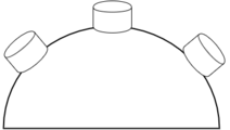
Ultrasonic mount Design
3D design


Ultrasonic Sensor
There are three ultrasonic sensors for the front of the car positioned at different angles to provide a wide ultrasonic "vision" for the car. The mount for the sensors was 3D printed such that we have the flexibility to change the angle of the sensor at a later stage when debugging the sensor.
Hardware Interface
In this section, you can describe how your hardware communicates, such as which BUSes used. You can discuss your driver implementation here, such that the Software Design section is isolated to talk about high level workings rather than inner working of your project.
Software Design and Implementation
The readings from the sensor is taken in the form of PWM signals with the help of interrupts. The following steps were performed to take readings and calculating distance from the sensor
- Configure the PW pin of sensor as input.
- Configure RX pin of the sensor as output and set it high.
- Enable the Rising and the Falling edge interrupt on the PW pin of the sensor.
- Start timer at the rising edge of the interrupt (time T1).
- At falling Edge of the interrupt stop the timer (time T2).
- The distance of the obstacle is = (T2-T1)/147 inches.
- Check for threshold distance. If distance > threshold distance for given sensor, then convey to master that obstacle was found.
- If middle sensor value has distance <= critical distance then convey then set critical bit, conveying that car must stop to avoid a collision
- Broadcast data on CAN bus.

I/O
Design & Implementation
The IO section for the car consists of two main components, an LCD screen and LED indicators.


IO is integral to troubleshooting the working of the car. The team first decided upon the various important indicators that would be needed to troubleshoot the working of the car and then decided to translate them into either LED indicators or LCD screen elements. The table below summarizes the features for IO and which IO element was used to represent them on the car.
| Sr.No | Sensor Pin Function | LCD Element | LED Element Present |
|---|---|---|---|
| 1 | System Command (Start, Stop Resume) | An on screen LED that turns off/on for each command | Yes |
| 2 | Right Turn | An on screen LED that turns off/on | Yes |
| 3 | Left Turn | An on screen LED that turns off/on | Yes |
| 4 | Brake | An on screen LED that turns off/on | Yes |
| 5 | Forward | An on screen LED that turns off/on | Yes |
| 6 | Reverse | An on screen LED that turns off/on | Yes |
| 7 | Right Sensor | Gauge | No |
| 8 | Left Sensor | Gauge | No |
| 9 | Middle Sensor | Gauge | No |
| 10 | Rear Sensor | An on screen LED that turns off/on | Yes |
| 11 | System Status (Heatbeat) | Gauge | No |
| 12 | Speed. | Meter. | No |
| 13 | Battery Indicator | Gauge | No |
Hardware Interface
The hardware interface for the LCD is through UART for LED it is through GPIO. LCD Hardware interface: The LCD controller works on UART communication. Uart-2 on SJONE board is used for sending the data and command to uLCD-32PTU.
We are using uLCD-32PTU to debug and display the important CAN message. We used this LCD because of following features:
- The uLCD-32PTU is a compact and cost effective Intelligent Display Module packed with plenty of features capable of being an interface controller for a number of applications.
- Built in extensive 4DGL graphics and system library functions.
- Simple UART communication at 9600 Baud rate is used to communicate with SJONE board.
LED hardware interface: For the LEDs we connected the the positive end to the VCC and the negative end to the GPIO. This was done to prevent the SJOne port from being the current source for a constantly glowing LED. There are 10 LEDs in total on the car. 4 in the front and 6 in the rear.


Software Design

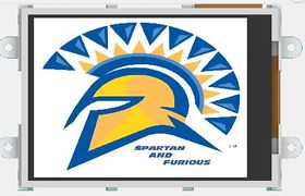
Form 0
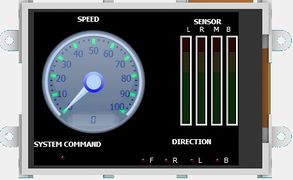
Form 1
Form 2
Form 3


- Form0: This is the home screen for Spartan and Furious which displays the logo of our team. This screen is displayed when there is no system command from the Master. As soon as the IO receives the master system command the IO displays all the relevant data using periodic callback function.
- Form1: This is the screen which is being displayed after the home screen. This screen shows the sensor data, Speed indication, System command status and the direction in which the car is moving.. There are four different gauges for different sensor Data. Each gauge indicates obstacle proximity detected from ultrasonic sensors which are placed on left (L), centre (M), right (R) and rear sensor at back (B) of the car. The direction of the car is indicated using different LEDs for Front(F), Right(R), Left(L), Back(B) indication. The system command LED indicates that master is in sync with all the modules.
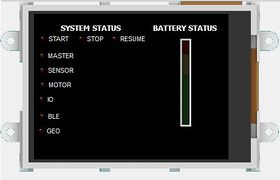
- Form2: In this screen IO displays the System Status of all the modules and also the System status given by the master module to all the modules. System status consists of start, stop and Resume status. There are six different LED’s indication the Heartbeat of the modules. There is a battery indicator Gauge which displays the battery life.
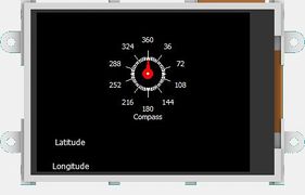
- Form3: This is the ‘Geo Status’ screen which shows different parameters such as GPS longitude and latitude, current compass direction and different modes of car.
The data is sent to the LCD in specified format.
For sending Gauge, LED, Speedometer data we need to send five bytes of data.
Byte1 - Event byte
Byte2 - Object type
Byte3 - Object number
Byte4 - Data byte 1
Byte5 - Check sum
For angular meter readings we have six bytes of data to be sent.
Byte1 - Event byte
Byte2 - Object type
Byte3 - Object number
Byte4 - Data byte 1
Byte5 - Data byte 2
Byte6 - Check sum
For String to be passed we need to have 3 bytes + each character as data byte + checksum byte.
Byte1 - Event byte
Byte2 - Object type
Byte3 - Object number
Byte4 - Data byte 1
Byte5 - Data byte 2
Byte6 - Data byte 3
.
.
.
Byte n+3 - Data byte n
Byte n+4 - Check sum
The data is sent to the LCD using UART. Following steps should be performed in order to display the readings on LCD.
- Wait for system command from master.
- Once master command has been received, collect CAN data for all information that has to be shown on IO.
- Update the corresponding LCD element, and toggle the LEDs based on data received.
- Switch LCD form every 5 seconds.
- If destination reached, show the destination reached form.
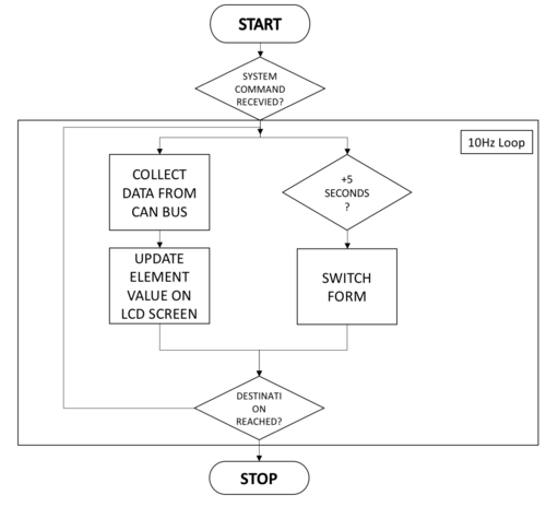
LCD code Flowchart
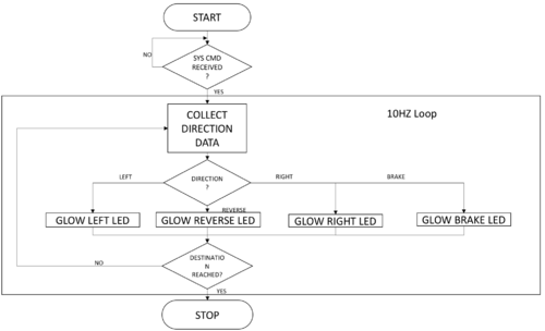
LED code Flowchart


Testing & Technical Challenges
Sensor Technical Challenges and Testing:
We have used sensor in PW mode. In this mode the major challenge was triggering of the sensor. We had to trigger four sensors in such a way that they do not interfere with each other. In order to tackle this issue we triggered front and rear sensor at same time and after a small delay we triggered right and left sensor at same time. The second major challenge is sensor reflection from ground and sensor mounting design. We had to mount the sensor with an angle of 20 degrees with the horizontal. Still there were some reflections but they were minimal. We designed 3D print for sensor mounting such that the angle between each sensor was exactly 60 degrees. The beam angle of sensor is 30 degrees in each side.
IO Technical challenges:
LCD mounting was the main challenge for IO. We were using LCD and LED for debugging purposes. For LED we connected same GPIO pins for front and back signal pins. So, the issue came with different colour LED’s. The LED which has less resistance draws all the power and only that LED was turning ON and OFF. The other LED was not showing any indication. We had to change both LED’s with same color and then it was working fine. The second issue was of common ground for LCD. We were sending data using UART and had given a Ground pin connection to LCD from the power source. There was no change in the LCD screens and then we figured out that it was due to no common ground connection.
Motor Controller
Group Members
Design & Implementation
The motor controller is responsible for generating the driving and steering action of the car. For this purpose, we have two types motors viz DC motor for driving and Servo motor which is used for changing directions of the car. The motor controller is also interfaced with a speed encoder for generating a feedback mechanism to automatically control and monitor the speed of the car. Our car came equipped with a Servo motor and brushed DC motor which is connected Electronic Speed Control (ESC).
Hardware Design

| SJOne Pin Diagram | ||
|---|---|---|
| Sr.No | Pin Number | Pin Function |
| 1 | P0.0 | CAN RX |
| 2 | P0.1 | CAN TX |
| 3 | P2.0 | Servo motor |
| 4 | P2.1 | DC motor |
| 5 | P2.5 | Speed Encoder |
- Hardware Specifications

1. DC Motor
Our car came with Titan 12T 550 brushed motor and waterproof ESC. The ESC drives the DC motor based on the Pulse Width modulation (PWM) applied to it. The power supply required for this motor is 8.4 V. Maximum speed of upto 30mph can be achieved. The rotational speed is proportional to the EMF generated in its coil and the torque is proportional to the current.The main connection pins driving the motor are VCC,GND and the Control pin (PWM). The pin P2.1 of SJ-one board is connected to supply the required PWM to the motor.
The basic working principle of DC motor is illustrated in the following figure :
Since the preprogrammed controller has to be replaced by using our design ,the DC motor is then tested with Digital Oscilloscope for getting the frequency of operation and equivalent PWM values for full throttle condition in the forward as well as backward condition.
It was observed from the waveform that the frequency of operation is 100Hz. The range of operational duty cycle is 10% to 20% with 15% being the neutral value or the stop condition.
In order to accelerate the car a PWM value in the range of 15.6%-20.0% is applied. The 15.6 is the minimum pickup PWM that should be supplied in order to get the car moving at full load.

2. Servo Motor
The servomotor used in the car is #2056 a waterproof all weather-action and double the steering power as compared to standard servos. The servo motor is responsible for controlling the steering action of right or left by applying a suitable PWM pulse. The servo motor can be driven with 3.3 V power supply. The pin P2.0 of SJ-one board is connected to supply the required PWM to the motor. After testing the servo motor, we found that the frequency of operation is 100Hz and the operational duty cycle range is 10.0%-20.0% with 15% being the neutral value. For a full right deflection, we provide input PWM pulse ranging from 15.0-20.0% and for full deflection to the left we apply 10.0-15.0% of PWM.


3. Speed Sensor
The speed feedback is monitored through the speed encoder which works on the Hall-effect principle.
The Hall-effect speed sensor works as a transducer whose output voltage varies in response to the magnetic field.
The sensor is mounted on the Spur gear instead of the wheel. The sensor would detect the rotation of axle. The motor controller would detect whenever the magnet is aligned with the sensor. This would generate a pulse. The pulse is detected in the form of rising-edge interrupt.
This gives the wheel rotation count. The wheel rotates for every 1/4th rotation of the spur gear. The rotation count can then be converted to rpm to calculate the speed of the car.
Hardware Interface
The CAN bus is used to send and receive messages to and from the Master Controller. The motor controller receives driving and steering signals from the master. The speed calculation is performed using the speed sensor and is sent on the bus, which will be received by the IO controller for display purposes.
Software Design
The following diagram describes the flow of the software implementation for the motor driver and speed feedback mechanism.


Implementation
The motor controller receives all its signals from Master controller from the CAN bus. The motor controller receives the steer and drive command from the master. The motor controller receives the System start command which boots and decodes further drive signals to the motor controller. Upon receiving the drive command the motor controller decodes the steering action. Upon receiving suitable data about the obstacle from sensor controller the master controller relays appropriate steering action. To achieve better performance in steering, the turn is categorized as FULL and HALF. This gives better precision in turning.
- Speed Regulation:
Upon detection of uphill the pulse received from the speed encoder reduces. This is detected and the motor feedback is designed such that the speed is increased by providing higher value of PWM value to drive the DC motor. Similarly, for downhill the pulse count received increases which is detected by the speed encoder and the speed is reduced by applying reduced PWM.
Testing & Technical Challenges
- Wheel Alignment Error
Though the neutral value of PWM is 15% at which the servo is supposed to be aligned straight. In practice, however when we tested the car for straight run slight deflection towards right was observed when the PWM pulse width was set to 15.0 %. Thus, to correct this, we provided correction value of -0.98 giving a resultant PWM pulse width of 14.02%. Thus, we fixed the wheel alignment and obtained the desired straight path traversal.
- Speed Sensor Assembly
The speed encoder was assembled on the spur gear of the car. The installation at first was such that outer fitting was large and was avoiding the pulse trigger by the magnet.As a result of which we were unable to modulate speed.Issue was resolved by using the correct outer assembly of the gear which generated the speed feedback.
Master Controller
Group Members
Introduction and Responsibilities
Master controller is the brain of the car.
All the decisions are taken by the master module. Some of the major responsibilities of the master module are:
- System command (Initial Start) : Upon successful connection with Android app, master command will send as system start command to all the other modules on the CAN bus. This command advises all the modules to start their processing(similar to wake up).
- Obstacle avoidance : Based on the sensor values, master will decide the direction to be taken by the motor.
- GPS data: Depending upon the GPS calculated direction and obstacle data received from sensor module, master controller will decide the steer and drive of the motor.
- Determine if all the modules on the bus are active or inactive.
The master controller using the data from other modules, drives the car safely to the destination.
Hardware Design
- Interface of CAN Bus with six SJ-One controller boards on PCB was designed.
- Ribbon Cables were used instead of individual jumper wires to assist in designing less complex circuit.

Software Design
Master Controller needs to periodically receive and transmit updated data from all the modules in order to make an efficient decision. Based on the priority of the data, corresponding CAN messages are parsed in 100Hz, 10Hz or 1Hz periodic scheduler tasks respectively. Data received can be viewed and traced in real time using PCAN View or BUS Master tool.
Software Implementation
The diagram below details out the flow of data to and from the Master Controller.

Heartbeat
Master Controller is responsible to identify if all the modules are active or inactive. All the modules send the heartbeat messages on the CAN Bus every 1Hz. If the heartbeat message is not received from any module, master marks the system status of the module as inactive. The system status message is update at run time on the I/O and the app. User can then reset the inactive module.
The code snippet for the receiving heartbeat messages and determining system status is as follows:
if(dbc_decode_BLE_HEARTBEAT(&ble_heartbeat_cmd, can_msg.data.bytes, &can_msg_hdr))
   system_status_message.MASTER_SYSTEM_STATUS_ble = 1;
if(dbc_decode_SENSOR_HEARTBEAT(&sensor_heartbeat_cmd, can_msg.data.bytes, &can_msg_hdr))
   system_status_message.MASTER_SYSTEM_STATUS_sensor = 1;
if(dbc_decode_GEO_HEARTBEAT(&geo_heartbeat_cmd, can_msg.data.bytes, &can_msg_hdr))
   system_status_message.MASTER_SYSTEM_STATUS_geo = 1;
if(dbc_decode_IO_HEARTBEAT(&io_heartbeat_cmd, can_msg.data.bytes, &can_msg_hdr))
   system_status_message.MASTER_SYSTEM_STATUS_io = 1;
if(dbc_decode_MOTOR_HEARTBEAT(&motor_heartbeat_cmd, can_msg.data.bytes, &can_msg_hdr))
   system_status_message.MASTER_SYSTEM_STATUS_motor = 1;
To determine the direction and throttle of the car, master controller needs the data from sensor and Geo module. These data are critical for the system and are parsed in 10Hz periodic tasks.
After the master receives BLE_CMD = START, master will send SYSTEM_CMD= START command to all of the modules, which notifies them that the Bluetooth communication via app has been initiated.
The car is capable of reaching a destination or just running while avoiding obstacles with no destination set.
The software design of the master controller supports two modes for the car:
Free Run mode
- For switching to free run mode, the “FREE RUN” button needs to be selected from the app.
- As per the sensor data, the movement of the car is decided by the master controller.
- By default the motor is commanded to move straight.
- If there is an obstacle in the middle sensor, then the sensor data for left and right sensor is checked.
- If there is an obstacle at a very short distance, critical obstacle bit is set and car is first stop.
- When the car needs to stop due to obstacles, reverse sensor value is checked.
- The car stops only when there are obstacles in all directions or user sends Stop from the app.
- The following table depicts the motor command sent by master to the motor controller as per the sensor values.
| Sr no | Left sensor value | Middle sensor value | Right sensor value | Critical value | Rear sensor value | Motor Command |
|---|---|---|---|---|---|---|
| 0 | 0 | 0 | 0 | 0 | X | STRAIGHT |
| 1 | 0 | 0 | 1 | 0 | X | HALF RIGHT |
| 2 | 0 | 1 | 0 | 0 | X | LEFT |
| 3 | 0 | 1 | 1 | 0 | X | RIGHT |
| 4 | 1 | 0 | 0 | 0 | X | HALF LEFT |
| 5 | 1 | 0 | 1 | 0 | X | STRAIGHT |
| 6 | 1 | 1 | 0 | 0 | X | LEFT |
| 7 | 1 | 1 | 1 | 0 | 0 | REVERSE |
| 8 | 1 | 1 | 1 | 0 | 1 | STOP |
| 9 | X | X | X | 1 | 0 | REVERSE |
| 10 | X | X | X | 1 | 1 | STOP |
- When STOP button is selected from the app,the BLE will advise the same to master controller and master will send SYSTEM_CMD= STOP to all the modules. This stop command notifies them that the Bluetooth communication via app has been deactivated.

- For switching to navigation mode, the “NAVIGATION MODE” button needs to be selected from the app.
- In this mode, Geo module sends the desired direction to the master controller.
- The master controller will check if there is any obstacle in the desired path.
- In case of obstacle, car moves as per the obstacle avoidance algorithm (free run mode).
- Once Destination Reached signal is received from the Geo module, the car stops.

Common Technical Challenges
Issue 1
One of the most unexpected issue faced during testing, was we were unable to receive data from motor and sensor module during testing for demo1. After debugging, we realized that the ribbon cable we purchased was meant for a special purpose and was shorted internally as shown in the picture because of which we were unable to receive data from the CAN bus.


Conclusion
This project has helped each one of us grow, not just academically, but professionally as well. This project did achieve the goals it promised, these were:
- CAN: Teaching us to work with the CAN bus and protocol; a simple, robust and noise immune mode of communication and using DBC files as a method of managing CAN messages.
- GIT: Using GIT as a method of continuous integration and improve productivity. GIT allowed us to work independent of our schedules, boosting our productivity beyond the time the team members met.
- Team Work: Working in a fairly large group gave us a real sense of team work and collaboration.
- Professionalism and accountability.
On testing the car we found a lot of practical hurdles that we had to overcome. Debugging issues was a large part of our efforts to improve the working of our car. To mention a few:
- Hardware issues:
- Ribbon Cable: Issues with ribbon cables, we found the hard way that the ribbon cable we initially used was for a specific purpose making it incompatible with our boards.
- Voltage fluctuation disrupting the CAN bus: Inconsistent soldering on on of the power rails, caused the CAN bus to fail altogether.
- Bluetooth bridge: Maintaining a Bluetooth connection between different activities in the app was a problem.
- Sensor: A section of code was rearranged to solve a problem that prevented the sensor from sending messages to the CAN bus.
- I/O: The I/O module is receiving a large amount of data, causing a task overrun. This was fixed by re-prioritizing the display and rearranging the code.
To the teams that are designing their car:
- Use a faster sensor and apply filters like a median or Gaussian filter to improve sensor performance.
- Ensure hardware connections are tested thoroughly.
- Start with the implementation for the Geo module early.
- Ensure that your Android App can communicate consistently with SJOne board.
Project Videos
CMPE243_F16_Spartan_and_Furious Demo Day Video
Project Source Code
References
Acknowledgement
We would like to acknowledge the following people for their help in completing this project:
- Preet for his invaluable teachings.
- The ISAs for their great advice and tips.
- Siddarth for helping with the design for our 3D mount.
- Maxbotix for a generous student discount on their product.
- Microchip for the free CAN ICs.
- Cratus Technologies for letting us use their 3D printer.
References Used
- LPC_USER_MANUAL
- CAN transceiver
- Haversine Formula Wikipedia
- Magnetometer Wikipedia
- MCP2551 Datasheet
- Hall Effect Sensor Wikipedia
- Ultimate GPS Adafruit
- uLCD-32PTU
- Maxbotix Ultrasonic Datasheet
- Adafruit Ina219 current sensor
- SparkFun Bluetooth Modem - BlueSMiRF Gold
- Android Bluetooth API Guid
- Maps Android API
- RPM sensor 6520 Installation Guide
- Configuration of Electronics Speed Control