Difference between revisions of "F22: Bob Burgers"
(→Hardware Implementation and Design) |
(→Software Implementation and Design) |
||
| Line 457: | Line 457: | ||
==== Software Implementation and Design==== | ==== Software Implementation and Design==== | ||
| − | We used premade 64x64 arrays | + | We used premade 64x64 arrays for the background and smaller arrays for game objects. Those arrays were set to refresh the matrix after anything was drawn on the board. The led task was in charge to reset the board to the original background after vtaskdelay was call. This was done to erased the previous positions of the ball or blocks after they had moved. |
| Line 467: | Line 467: | ||
} | } | ||
} | } | ||
| + | |||
| + | |||
| + | |||
| + | A background driver was created to introduced full objects to the game. Instead of updating every pixel at a time to create a ball or block, the background driver takes in different size arrays and adds them to the game. There are multiple functions for different game objects but they work the same. All they require is the axis of the pins and the size of the arrays. This made it easier to code the movement of the objects by just following the first pixel of the object in the display. Instead of updating every pixel at a time, the led matrix buffer as a whole will be refresh whenever a new pixel was added. If an object was only on the top or bottom half, the other side was set to off. | ||
static void fill_word(uint8_t y, uint8_t x, uint8_t array_x, uint8_t array_y, uint8_t insert_word[array_y][array_x], | static void fill_word(uint8_t y, uint8_t x, uint8_t array_x, uint8_t array_y, uint8_t insert_word[array_y][array_x], | ||
| Line 480: | Line 484: | ||
} | } | ||
} | } | ||
| + | |||
| + | |||
| + | Finally, the led task is runs all of this functions to set up the display. The psuedocode below demonstrate the events the task goes through. | ||
| + | |||
| + | Pseudocode | ||
=== Implementation === | === Implementation === | ||
Revision as of 05:15, 15 December 2022

Contents
Project Title
SOCCER PONG
Abstract
At the time this project was created (fall 2022), the soccer world cup was taking place. Having caught a little of the world cup fever, Soccer Pong looks to combine the gameplay from soccer and the original Pong. Two games from different mediums but with great symmetry. Two players will face each trying to avoid being scored on. A ball will bounce from any surface that is not in the penalty area. Once a player has read the set maximum number of goals, a victor will be crowned. Press the reset button and let’s go again!!! Soccer Pong brings a new flavor to a historic game, taking you into the world of soccer.
Objectives & Introduction
The main objecive of this game was to create a simple pong game and then change it to something more unique. The following were the objectives we had to reach our goal.
- Create a Matrix Driver to display all of the visuals of the game.
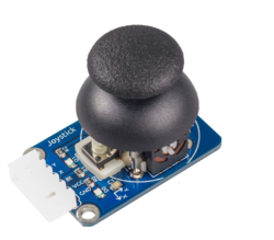
- Implement ADC joysticks controllers Driver to handle the players blocks movement
- Implement Reset and Pause buttons using semaphores interrupts to reset the game and pause the ball movement
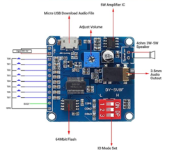
- Incorporate music and special effects by adding a mp3 modules with UART interface.
- Design a PCB that will combine all of the peripherals dfevics with the sj2 board and matrix.
- Create a task that will refresh the matrix driver buffer with the ball and player movement.
- Develop control system with the ability to modify speed and size of blocks
- Create task that will handle ball movement, placement, and hit detection.
- Incorporate the music and sound effects after specific time based events (hitting block, goal, etc).
- Integrate the pause and reset buttons
Team Members & Responsibilities
William Hernandez

Responsibilities
- Led Matrix Graphics
- Gameplay Logic
- Music System Integration
- Game Objects and Hit Detection
- Debugging and Testing
Tin Nguyen
- File:Put picture file here
- PCB
- Music Development
Matthew Hanna

Responsibilities
- Joystick input with ADC reading potentiometer positions for paddle movement
- GPIO input for button pressing pause and reset
- locking mechanism for game pausing and game reset loop entrance
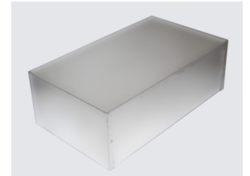
- enclosure fabrication
Schedule
| Week# | Start Date | End Date | Task | Status |
|---|---|---|---|---|
| 1 |
|
|
|
|
| 2 |
|
|
|
|
| 3 |
|
|
|
|
| 4 |
|
|
|
|
| 5 |
|
|
|
|
| 6 |
|
|
|
|
| 7 |
|
|
|
|
| 8 |
|
|
|
|
| 9 |
|
|
|
|
| 10 |
|
|
|
|
General Parts
| Item # | Part | Seller | Quantity | Total Cost |
|---|---|---|---|---|
| 1 | 64x64 RGB LED Matrix | Sparkfun | 1 | $85.95 |
| 2 | SJ-2 Boards | SJSU | 1 | $50.00 |
| 4 | PEMENOL Voice Playback Module | Amazon | 1 | $10.19 |
| 5 | Joysticks | Amazon | 2 | $20.00 |
| 6 | 5v Power Supply | Amazon | 1 | $15.19 |
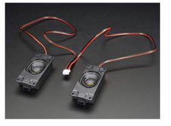
| 7 | Enclosed Speaker Set - 3W 4 Ohm | Amazon | 1 | $12.48 |
| 8 | Buttons | Amazon | 2 | $8.95 |
| 9 | Standoffs | Amazon | 1 | $24.95 |
| 10 | PCB | [link Seller] | 1 | $40.00 |
| 11 | Aluminum Enclosure | Anchor Electronics | 1 | $45.12 |
Design & Implementation
The design section can go over your hardware and software design. Organize this section using sub-sections that go over your design and implementation.
Pin Configuration
-
Pin# LED Matrix Pin SJ-2 PIN R1 High Red Led Data P0_6 G1 High Green Led Data P0_7 B1 High Blue Led Data P0_8 R2 Low Red Led Data P0_26 G2 Low Green Led Data P0_9 B2 Low Blue Led Data P1_31 A Mux row select A P1_20 B Mux row select B P1_23 C Mux row select C P1_28 D Mux row select D P1_29 E Mux row select E P2_4 OE Output Enable P2_2 LAT Data Latch P2_1 CLK Clock Signal P2_0 MP3 Module RX UART Receive P4_28 TX UART Transmitter P4_29 Buttons Either Pin Pause Button P2_5 Either Pin Reset Button P2_6 Joysticks X Player 1 P1_30 X Player 2 P0_25 Hardware Design
Discuss your hardware design here. Show detailed schematics, and the interface here.
Hardware Interface
In this section, you can describe how your hardware communicates, such as which BUSes used. You can discuss your driver implementation here, such that the Software Design section is isolated to talk about high level workings rather than inner working of your project.
Software Design
Show your software design. For example, if you are designing an MP3 Player, show the tasks that you are using, and what they are doing at a high level. Do not show the details of the code. For example, do not show exact code, but you may show psuedocode and fragments of code. Keep in mind that you are showing DESIGN of your software, not the inner workings of it.
Led Matrix
Hardware Implementation and Design
All the pins were set up to be close to each other for better readability. The led matrix required 16 pins as specified above with two being ground. It required 5v with at least 2.1A current. The led matrix uses daisy chaing shift registers to set up the rows. The RGB1 pins set up the color of the top half leds and the RGB2 pins set up the color of the lower half leds. To control the lower half leds both RGB1 and RGB2 need to be set simultaneously. The matrix is 64x64, but works more like a 32x64 matrix. Pins A through E will select the row of the top half. For example, pixel 32x1, will light up when pixel 1x1 is on. This means that both RGB1 and RGB2 need to be set or reset simultaneously. For one pixel to be set, all other pixels need to be reset.
Software Implementation and Design
We used premade 64x64 arrays for the background and smaller arrays for game objects. Those arrays were set to refresh the matrix after anything was drawn on the board. The led task was in charge to reset the board to the original background after vtaskdelay was call. This was done to erased the previous positions of the ball or blocks after they had moved.
void led_driver__refill_refresh(uint8_t (*update_matrix)[64]) {
 for (int row = 0; row < 64; row++) {
   for (int col = 0; col < 64; col++) {
     led_matrix_refresh_array[row][col] = update_matrix[row][col];
   }
 }
}
A background driver was created to introduced full objects to the game. Instead of updating every pixel at a time to create a ball or block, the background driver takes in different size arrays and adds them to the game. There are multiple functions for different game objects but they work the same. All they require is the axis of the pins and the size of the arrays. This made it easier to code the movement of the objects by just following the first pixel of the object in the display. Instead of updating every pixel at a time, the led matrix buffer as a whole will be refresh whenever a new pixel was added. If an object was only on the top or bottom half, the other side was set to off.
static void fill_word(uint8_t y, uint8_t x, uint8_t array_x, uint8_t array_y, uint8_t insert_word[array_y][array_x],
                     color_code color) {
 for (int row = 0; row < array_y; row++) {
   for (int col = 0; col < array_x; col++) {
     if (insert_word[row][col] == 1) {
       led_driver__setPixel(row + y, col + x, color);
     } else {
       led_driver__setPixel(row + y, col + x, insert_word[row][col]);
     }
   }
 }
}
Finally, the led task is runs all of this functions to set up the display. The psuedocode below demonstrate the events the task goes through.Pseudocode
Implementation
This section includes implementation, but again, not the details, just the high level. For example, you can list the steps it takes to communicate over a sensor, or the steps needed to write a page of memory onto SPI Flash. You can include sub-sections for each of your component implementation.
Testing & Technical Challenges
Describe the challenges of your project. What advise would you give yourself or someone else if your project can be started from scratch again? Make a smooth transition to testing section and described what it took to test your project.
Include sub-sections that list out a problem and solution, such as:
<Bug/issue name>
Bugs
- Joystick input had a fixed paddle speed
- Pause and Reset buttons service with ISR was difficult to debounce, moving button input detection to a Task would be more practical
Conclusion
Conclude your project here. You can recap your testing and problems. You should address the "so what" part here to indicate what you ultimately learnt from this project. How has this project increased your knowledge?
Project Video
Project Source Code
References
Acknowledgement
Any acknowledgement that you may wish to provide can be included here.
References Used
List any references used in project.
Appendix
You can list the references you used.


