F22: Space Warriors
Contents
Grading Criteria
- How well is Software & Hardware Design described?
- How well can this report be used to reproduce this project?
- Code Quality
- Overall Report Quality:
- Software Block Diagrams
- Hardware Block Diagrams
- Schematic Quality
- Quality of technical challenges and solutions adopted.
Lumberjack
We will put photos of our game here.
Abstract
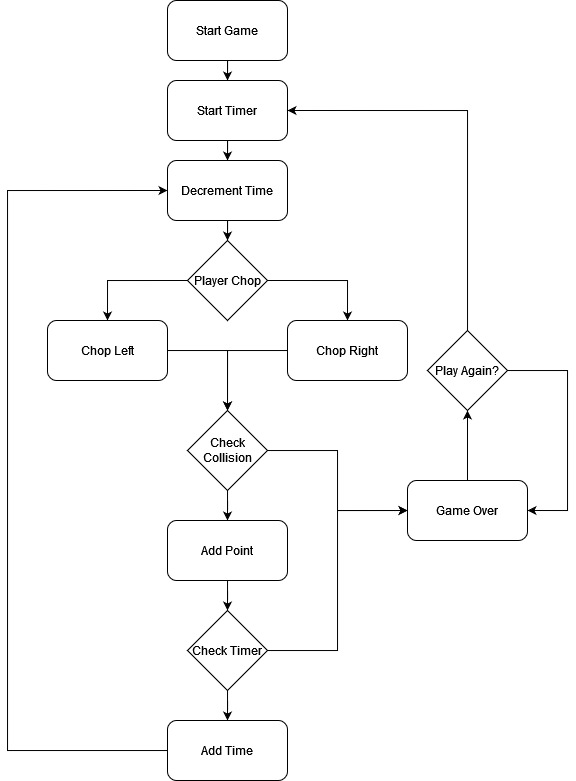
Lumberjack is a reaction-based game with the objective of chopping down a tree while avoiding the incoming branches. The project will be a re-creation of a mobile game called Timber Guy, using an LED matrix array and momentary switch buttons to interface with the game. Players will continuously cut down a tree by pressing between the left and right buttons to make the character chop the tree. Meanwhile, they must also dodge the descending branches of the tree. By touching the respective buttons on the left or right sides of the LED display, players will move the character to avoid getting hit. Moreover, the players must continuously cut down the tree, which restores the countdown timer, faster than it is depleted. If the player collides with a branch or the countdown is depleted, the game will be considered over.
Objectives & Introduction
The objective of the project was to re-create a mobile game, Timber Guy, designed around FreeRTOS and the SJ2C board. In doing so, our team set out to achieve the following goals:
- Smooth display graphics during game play
- Synchronize game audio with game play
- Utilize the SD card as part of our design
- Further explore synchronization and task prioritization of tasks in an RTOS within a more complex application
Team Members & Responsibilities
Dhanush Babu
- Develop Game Logic.
- Game State Machine handling.
- Develop Drivers for hardware.
- Integrating Hardware and Software
- Game logic testing and debugging.
Nick Tran
- Develop drivers for LED Matrix.
- Develop graphics drivers for displaying defined images to LED Matrix.
- Develop BMP drivers for loading bmp image files from SD card to use with the graphics driver.
- Made the enclosure and body of the system.
- Game logic integration, testing and debugging.
Rajveer Singh Kaushal
- Develop Drivers for MP3 Decoder.
- Wiki Page Manager.
- Game logic testing and debugging.
Schedule
| Week# | Start Date | End Date | Task | Status |
|---|---|---|---|---|
| 1 |
|
|
|
|
| 2 |
|
|
|
|
| 3 |
|
|
|
|
| 4 |
|
|
|
|
| 5 |
|
|
|
|
| 6 |
|
|
|
|
| 7 |
|
|
|
|
| 8 |
|
|
|
|
| 9 |
|
|
|
|
| 10 |
|
|
|
|
Parts List & Cost
| Item# | Description | Quantity | Price |
|---|---|---|---|
| 1 |
SJ2C Board |
1 |
$50.00 |
| 2 |
LED Display |
1 |
$85.95 |
| 3 |
Momentary switches |
5 Pack |
$8.99 |
| 4 |
Jumper wires |
Pack |
$6.99 |
| 5 |
5V Power Supply |
1 |
$ 16.99 |
| 6 |
MP3 serial module |
1 |
$ 8.39 |
| 7 |
Game enclosure (wood / paint / adhesive) |
Misc |
$ 30.00 |
Design & Implementation
The design section can go over your hardware and software design. Organize this section using sub-sections that go over your design and implementation.
Hardware Design
Discuss your hardware design here. Show detailed schematics, and the interface here.
Hardware Interface
In this section, you can describe how your hardware communicates, such as which BUSes used. You can discuss your driver implementation here, such that the Software Design section is isolated to talk about high level workings rather than inner working of your project.
LED Matrix Display
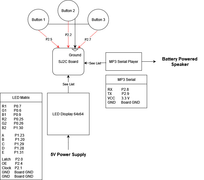
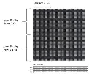
The 64 x 64 LED matrix contains a total of 4096 pixels, with each pixel having 3 channels for red, green, and blue colors. Each group of 32 rows of the display is addressable by using a 5:32 decoder, where each 5-bit address actually selects 2 rows of the 64 x 64 display at a time. Therefore, the display can be considered to be split in two halves -- the upper display containing rows 0 to 31, and the lower half display comprised of rows 32 through 64. To turn each LED on, a HIGH must be asserted on the respective RGB pins and clocked into the respective bit of the 64-bit shift registers, where each bit position is relative to the 64 columns of the display. Since the display is split into two halves, pins R1, G1, and B2 control the color output for the upper display while pins R2, G2, and B2 control the output for the lower half of the matrix.
Momentary Press Buttons
TO DO
MP3 Serial Player
TO DO
Software Design
Show your software design. For example, if you are designing an MP3 Player, show the tasks that you are using, and what they are doing at a high level. Do not show the details of the code. For example, do not show exact code, but you may show psuedocode and fragments of code. Keep in mind that you are showing DESIGN of your software, not the inner workings of it.
Implementation
This section includes implementation, but again, not the details, just the high level. For example, you can list the steps it takes to communicate over a sensor, or the steps needed to write a page of memory onto SPI Flash. You can include sub-sections for each of your component implementation.
Game Logic State Machine
TO DO
BMP Driver
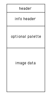
The game graphics were designed in a paint utility mtPaint, saved onto an SD card, and read into memory to display onto the LED matrix. The structure of a bmp file is as illustrated below, the first 54 bytes are header data which contains information such as file identifier codes, file size, and byte offset to the start of the image data. The next section is the info header which contains information such as image width and height. The bmp files generated from mtPaint did not contain any palette information. Lastly, the bmp file format stores an image's pixel data in sequence, row by row, starting from the bottom left corner of an image, and ending in the top right corner. The bmp format stores each pixel using 3 bytes with each byte in blue, green, and red order. It's important to note that each row of an image's data is store in multiples of 4 bytes with padding to fill the extra bytes.
To check for padding bytes:

padding bytes = (image_width * 3 bytes_per_pixel) % 4
Display Driver
The driver iterates through each index of a 64 x 64 array in memory representing the LED display matrix and sets the respective RGB pins high to achieve the range of 3-bit colors possible with the display. Each pixel's RGB value is then clocked into the 64-bit shift registers of each row. In this fashion, when the display is turned on, only one row is displayed at a time. However, because the process repeats so fast between all the rows, our eyes perceive the display as showing one consistent image.
The high level idea of how the display driver works is outlined in the code snippet below:
for(each row, while row is less than 64)
{
  1. turn off the display
  2. Set the 5-bit address to select the row to write to

  for(each col, while col is less than 64)
  {
     3. Check the value for (row, col) in our pixel buffer
     4. If the pixel contains red, green, or blue, set the the respective GPIO to HIGH
     5. Clock the data in
  }
}
6. Turn the display on to show the image
7. Delay -- acts like PWM to adjust screen brightness
8. Turn the display back off -- help to prevent rows 31 and 63 from uneven brightness
Testing & Technical Challenges
Describe the challenges of your project. What advise would you give yourself or someone else if your project can be started from scratch again? Make a smooth transition to testing section and described what it took to test your project.
Include sub-sections that list out a problem and solution, such as:
<Bug/issue name>
Discuss the issue and resolution.
Conclusion
Conclude your project here. You can recap your testing and problems. You should address the "so what" part here to indicate what you ultimately learnt from this project. How has this project increased your knowledge?
Project Video
Upload a video of your project and post the link here.
Project Source Code
References
Acknowledgement
Any acknowledgement that you may wish to provide can be included here.


