S14: Androbot
Contents
Project Title
ANDROBOT
Abstract
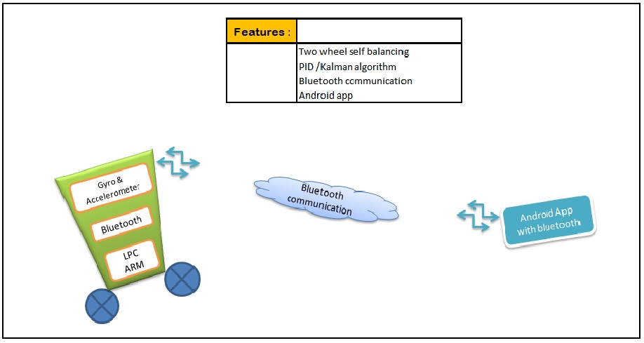
Androbot is a self balancing robot. The robot maintains it's balance using the IMU 6050 sensor. The values of accelerometer and gyroscope from the IMU sensor help in controlling the stepper motor. The wheels are connected to the stepper motor. The movements of the robot can be controlled using a Android phone app via Bluetooth.
Objectives & Introduction
Objectives.
- To develop a self balancing robot using accelerometer and gyroscope.
- To control the motion of the robot using Bluetooth module.
- To develop an Android application for the motion control.
Team Members & Responsibilities
- Digvijay Patil
- Driver Development + Android App Development
- Mahesh Chudasama
- Mechanical Design + Android App Development
- Shashank Tupkar
- FreeRTOS Software Design + Android App Development
Schedule
| Week# | Date | Task | Actual |
|---|---|---|---|
| 1 | 03/6 | Project role distribution | Completed |
| 2 | 03/13 | Partlist discussion and Block Diagram | Completed |
| 3 | 03/16 | Partlist finalization and Circuit Schematic | Completed |
| 4 | 03/20 | Ordering parts and components | Completed |
| 5 | 03/27 | Mechanical assembly, Hardware and Android app layout, Interfacing GY 521 With SJ One Board | Completed |
| 6 | 04/03 | Hardware test and Kalman Filter firmware coding | Completed |
| 7 | 04/10 | Test and debug part (a) Self balancing robot | In progress |
| 8 | 04/17 | Android app creation for Bluetooth module testing | Completed |
| 9 | 04/24 | Integrating Android app with Bluetooth module | Completed |
| 10 | 05/01 | Testing and debug | Not Completed |
| 11 | 05/08 | Testing and debug | Not Completed |
| 12 | 05/15 | Demo | Not Completed |
Parts List & Cost
The table below summarizes the parts used and the cost for the Androbot project till now. (To be completed)
| Sr. No. | Part | Description | Qty | Total Cost |
|---|---|---|---|---|
| 1 | SJOne Board | ARM Cortex M3 | 1 | $80.00 |
| 2 | Stepper Motor 1.8* | NEMA 17 12 V Step size = 1.8* Imax = 400 mA |
2 | $12.99 |
| 3 | Wheel | Diameter : 9 CM Width : 0.5" |
2 | $9 |
| 4 | Shaft Coupler | To couple wheel with motor shaft | 2 | $6.99 |
| 5 | ULN2004 IC | Motor driver IC Number of Buffers inverter/IC : 7 Imax = 500 mA |
2 | $0.65 |
| 6 | 16 Pin IC holder | To hold ULN2004 IC , So in case of IC failure, we can replace it immediately | 2 | $1.3 |
| 7 | IMU6050 | 6 Axis Gyro + Aceelerometer +- 1.5 g |
1 | $7 |
| 8 | Battery- Light weight | NIMH = 12V 2000 mAH Weight : 434 oz |
1 | $19.99 |
| 9 | HC-05 Bluetooth Module | Sensitivity : 80 dBm Operating Voltage : 1.8 to 3.6 V Output : UART Data rate : Variable |
1 | $12 |
| 10 | Chassis | Made from plastic tiffin box by cutting it from 3" Height | 1 | $6 |
| 11 | Strip connector | To connect development board with prototype board | 2 | $3 |
| 12 | Prototype Board | For implementing driver circuitry | 1 | $5 |
| Total Cost | $163.92 |
Design & Implementation
Hardware Design
Discuss your hardware design here. Show detailed schematics, and the interface here.

Hardware Interface
In this section, you can describe how your hardware communicates, such as which BUSes used. You can discuss your driver implementation here, such that the Software Design section is isolated to talk about high level workings rather than inner working of your project.
Software Design
Show your software design. For example, if you are designing an MP3 Player, show the tasks that you are using, and what they are doing at a high level. Do not show the details of the code. For example, do not show exact code, but you may show psuedocode and fragments of code. Keep in mind that you are showing DESIGN of your software, not the inner workings of it.
Implementation
This section includes implementation, but again, not the details, just the high level. For example, you can list the steps it takes to communicate over a sensor, or the steps needed to write a page of memory onto SPI Flash. You can include sub-sections for each of your component implementation.
Testing & Technical Challenges
Describe the challenges of your project. What advise would you give yourself or someone else if your project can be started from scratch again? Make a smooth transition to testing section and described what it took to test your project.
Include sub-sections that list out a problem and solution, such as:
Issue #1
Deciding the motors and battery. (To be completed)
Issue #2
Deciding the the body of the bot. (To be completed) We did not want our robot to be very heavy and consume more voltage.
Issue #3
- Interfacing GY-521(Accelerometer and Gyroscope Sensor) board with the SJ One board.
IMU MPU 6050 works on I2C and SPI both. We decided to go with I2C as I2C state machine was already written. There were number of issues faced here:
- 1. Getting the proper address of the IMU for initiating the communication. The tricky part here is if AD0 pin of IMU sensor is pulled low the address is 0x68 and if its pulled high the address is 0x69. This took a while to figure out.
- 2. MPU 6050 once it is initialized by writing the specified registers, you do not have to again write the registers for reading the data. To get the data just keep on reading the specified registers for values.
- 3. The data in the register comes in 2 bytes with the MSB byte first. So first left shift the values of MSB by 8 and concatenate it with LSB. The difficult part is to get the data in the exact format which took while to figure as there is no basis to decide whether the data is correct or not. The data acquired and the data concatenated should be in the uint_8 format.
Issue #4
We did not use the encoders so we could not find the exact position of the wheels. We could not decide by how many steps each of the wheel rotated.
Conclusion
Conclude your project here. You can recap your testing and problems. You should address the "so what" part here to indicate what you ultimately learnt from this project. How has this project increased your knowledge?
Project Video
Upload a video of your project and post the link here.
Project Source Code
Send me your zipped source code and I will upload this to SourceForge and link it for you.
References
Acknowledgement
Any acknowledgement that you may wish to provide can be included here.
References Used
[1] http://www.cdiweb.com/datasheets/invensense/PS-MPU-6000A.pdf
[2] http://www.starlino.com/imu_guide.html
[3] http://www.botched.co.uk/pic-tutorials/mpu6050-setup-data-aquisition/
Appendix
You can list the references you used.