Difference between revisions of "S16: Biker Assist"
Proj user11 (talk | contribs) (→Hardware Design) |
Proj user11 (talk | contribs) (→Hardware Design) |
||
| Line 345: | Line 345: | ||
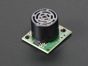
[[File:CMPE_244_S16_Biker_Assist_Maxbotix_Distance_Sensor.jpg|left|800px|thumb|Maxbotix Distance Sensor]] | [[File:CMPE_244_S16_Biker_Assist_Maxbotix_Distance_Sensor.jpg|left|800px|thumb|Maxbotix Distance Sensor]] | ||
[[File:CMPE_244_S16_Biker_Assist_Ultrasonic_wave_working.png|centre|300px|thumb|Ultrasonic Wave Working]]<br> | [[File:CMPE_244_S16_Biker_Assist_Ultrasonic_wave_working.png|centre|300px|thumb|Ultrasonic Wave Working]]<br> | ||
| − | [[File:CMPE_244_S16_Biker_Assist_Ultrasonic_wave_working_2.gif|centre| | + | [[File:CMPE_244_S16_Biker_Assist_Ultrasonic_wave_working_2.gif|centre|1024px|thumb|Ultrasonic Sensor Working]]<br> |
'''Bean Pattern'''<br> | '''Bean Pattern'''<br> | ||
The sensor has a calibrated beam pattern.The diagram below shows the approximate beam pattern and the detection area.One can select the distance sensor matching their needs depending on the pattern and the range of the beam. The beam patterns help identify an estimated detection zone for an application based on the acoustic properties of a target versus the plotted beam patterns. Each beam pattern is a 2D representation of the detection area of the sensor. The beam pattern is actually shaped like a 3D cone (having the same detection pattern both vertically and horizontally). | The sensor has a calibrated beam pattern.The diagram below shows the approximate beam pattern and the detection area.One can select the distance sensor matching their needs depending on the pattern and the range of the beam. The beam patterns help identify an estimated detection zone for an application based on the acoustic properties of a target versus the plotted beam patterns. Each beam pattern is a 2D representation of the detection area of the sensor. The beam pattern is actually shaped like a 3D cone (having the same detection pattern both vertically and horizontally). | ||
Revision as of 09:09, 22 May 2016
Contents
- 1 Biker Assist
- 2 Abstract
- 3 Objectives & Introduction
- 4 Project Schedule
- 5 Parts List & Cost
- 6 Design & Implementation
- 7 Testing & Technical Challenges
- 8 Conclusion
- 9 References
Biker Assist
Abstract
There are 60 million bicyclists on the road in the United States and 500,000 emergency department visits are due to bicycle-related injuries. The Biker Assist system increases the safety of bicyclists by improving how the bicyclist communicates with the rest of the road. Currently, the only way a bicyclist can signal to another vehicle that they are making a turn is by extending their arm in that direction, we propose a better way to accomplish this by using lights on the back of the bicyclist. These lights operate seamlessly and automatically without any input from the bicyclist so that the bicyclist can keep his attention on the road. There are distance sensors on each side of the bicyclist that alert the bicyclist of any vehicles in their blind spot by using a simple text-to-speech system. Also, the headlights operate automatically, turning on only when it is night time and turning off during the day time, without any direct input from the user.
Objectives & Introduction
- Obstacle detection using ultrasonic sensor
- Communication with Text-to-Speech module
- Interfacing with LED strips and SJOne board
- Design of PCB shield for the SJOne board
- Controlling front headlight using SJOne board's light sensor
Team Members
Roles and Responsibilities
- Adnan Dzebic & Nitesh Jain
- LED Strip Design
- PCB Design
- Urvashi Agarwal & Amit Pachore
- Distance Sensor Design
- Turn Angle Sensor Design
- Text-to-Speech Module
- 3D Designs
Project Schedule
| Sr. No. | Start Date | End Date | Task | Status | Actual Completion Date |
|---|---|---|---|---|---|
| 1 | 03/22/2016 | 03/28/2016 | Ordering the components | Completed | 04/02/2016 |
| 2 | 03/22/2016 | 04/04/2016 | Reading data sheet and understanding the components | Completed | 04/04/2016 |
| 3 | 03/29/2016 | 04/15/2016 | Algorithm design and Coding | Completed | 04/15/2016 |
| 4 | 04/15/2016 | 04/25/2016 | Distance sensor interfacing and Testing | Completed | 05/01/2016 |
| 5 | 04/15/2016 | 04/25/2016 | Automatic light interfacing and testing | Completed | 05/01/2016 |
| 6 | 04/26/2016 | 05/02/2016 | Integrating and testing | Completed | 05/16/2016 |
| 7 | 05/03/2016 | 05/16/2016 | Testing and adding extra features | Completed | 05/18/2016 |
| 8 | 05/17/2016 | 05/23/2016 | Final testing and Demo | Will complete on 05/23/2016 | 05/23/2016 |
Parts List & Cost
| Sr. No | Part Name | Source of Purchase | Part Number | Quantity | Cost($) |
|---|---|---|---|---|---|
| 1 | Distance Sensor | Maxbotix | MB1260 | 2 | 120.00 |
| 2 | Hall Effect Sensor | Digikey | MLX09215 | 2 | 8.52 |
| 3 | Thinpot | Digikey | TSP-L-0050-103 | 2 | 10.12 |
| 4 | Wiper | Digikey | WP-M1-01-03-014-DI | 2 | 10.12 |
| 5 | LED Strip 1 | Neo pIxel LED Strip | 2 | 10.12 | |
| 6 | LED Strip 2 | Amazon | RGB LED Strip | 2 | 30.00 |
| 8 | MOSFET | Excess Solutions | NTD5865N | 1 | 1.00 |
| 9 | Hardware | Excess Solutions | Screws, Nuts, Bolts, Spacers | 10 | 5.00 |
| 10 | Miscellaneous | Excess Solutions | Connectors, Heat Shrink | 10 | 7.98 |
Design & Implementation
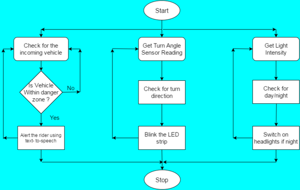
Overall Systems Flow
PCB
Design
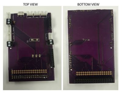
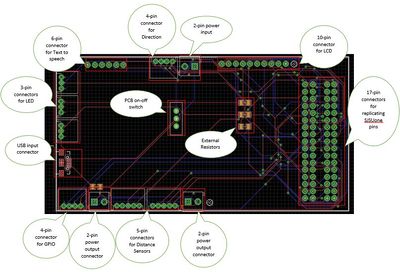
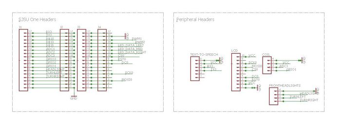
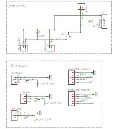
We designed a custom 10x5.5 inch PCB for our project where we integrated different modules together along with the SJSUone board. The PCB connects to the text to speech module, direction detection module, sensor module, LED’s and the SJSUone board. We replicated all the pins from SJSUone board also for further functionalities.
EAGLE PCB Design Tool
To Design our customized PCB, we used the EAGLE 7.5.0 Freeware tool. EAGLE stands for, Easily Applicable Graphical Layout Editor. EAGLE contains a schematic editor, for designing circuit diagrams. Parts can be placed on many sheets and connected together through ports. The PCB layout editor allows back annotation to the schematic and auto-routing to automatically connect traces based on the connections defined in the schematic. EAGLE saves Gerber and PostScript layout files and Excellon and Sieb & Meyer drill files. These standard files are accepted by many PCB fabrication companies.
The tool provides us with many types of connectors and devices commonly used in PCB’s. Using a drag n drop methodology and by applying the connection internally, different ports can be joined. In our PCB design, we used a lot connectors with different pin configuration for different peripherals including 3-pin,4-pin,5-pin,10-pin and 17-pin connectors. Also we placed a switch for turning on-off the board. There are 2 power input sources: one is USB and second is normal power connector. To provide power to the various peripherals attached, we have 2 output power sources also. To maintain the integrity of the PCB, we grounded the unused area and unused pins from the PCB. Since we used a free tool, the max PCB size could only be 10inch x 5.5inch. The blue lines indicate the connection made from the bottom and red lines from the top. To avoid shorting of pin connections, we used through holes.
In order to design a PCB, we need to know the type of connectors to place. And to decide the type of connectors, we must know 3 things: Library, Package and Device name. Adafruit provides us with libraries that can be used for a variety of functions. Packages differentiate the type of connectors and Device defines the different types of connectors inside the Package that needs to be used. Below is a list of all the connectors that we used in this PCB and their library, package and device:
EAGLE CONNECTOR LIST
| Purpose | Connector Type | Library | Package | Device Name |
|---|---|---|---|---|
| Power | 3x2-pin | SparkFun-Connectors | SCREWTERMINAL-3.5MM-2 | M023.5MM (M02) |
| Power | USB | SparkFun-Connectors | USB-AB-MICRO-SMD_V03 | USB-ABCONN-11794 (USB-AB) |
| Power | Capacitors | SparkFun-Capacitors | 1206 | CAP1206(CAP) |
| SJSUone Board | 4x17-pin | SparkFun-Connectors | 1X17_NO_SILK | M17NOSILK (M17) |
| Text To Speech | 1x6-pin | SparkFun-Connectors | 1X06_NO_SILK | M06NO_SILK_FEMALE_PTH (M06) |
| Distance Sensors | 2x5-pin | SparkFun-Connectors | JST-5-PTH | M05JST (M05) |
| Direction Sensor | 1x4-pin | SparkFun-Connectors | JST-4-PTH | M04JST- PTH (M04) |
| Extra GPIO | 1x4-pin | SparkFun-Connectors | JST-4-PTH | M04JST- PTH (M04) |
| LED | 3x3-pin | SparkFun-Connectors | JST-3-PTH | M03JST- PTH (M03) |
| LCD | 1x10-pin | SparkFun-Connectors | 1x10_NO_SILK | M10NO_SILK_PTH_FEMALE (M10) |
Turn Angle Detection Sensor
Hardware Design
A turn angle detection sensor is used to detect the exact measure of turn of the bike handlebar. This angle measurement is used to determine if the bike is taking turns. This sensor design has two different approaches. These are varying resistance approach and hall effect approach. Finally, we settled on using thinpot which works on the varying resistance approach. These two methods are explained below.
Varying Resistance Sensor
This sensor functions using the principle of Ohm's law. This law dictates that the current is inversely proportional to resistance for a given voltage. The sensor has three terminals, two end points for connecting voltage across sensor and one middle terminal called wiper. As the wiper terminal traverse over the coil, sensor gives varying resistance across wiper and one of the other terminals and hence varying voltage. Varying voltage output pin is connected to the ADC of the micro-controller and exact turn angle can be determined. We worked on two different sensors working on this principle.
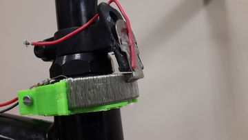
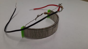
Custom Resistance Coil
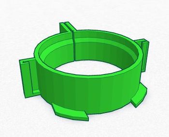
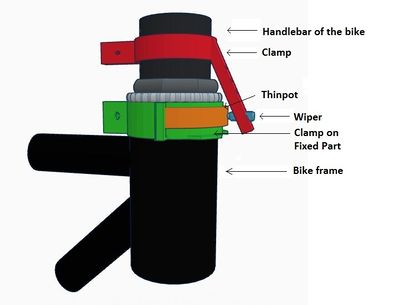
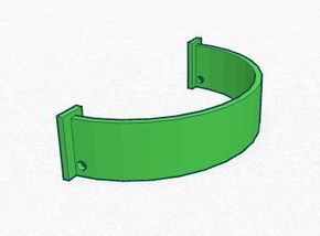
To detect turn angle, we designed our custom coil. We wound high resistance wire on a semicircular base to look like a coil. This coil was attached to the fixed part of the bicycle. The third terminal acting as a wiper was attached to the moving part of the handlebar such that, it traverses over the coil. We attached two resistances of value 10K were attached before connecting to the battery. These two circuits formed a potential divider circuit and also avoided battery short circuit.
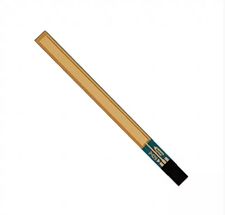
Thinpot
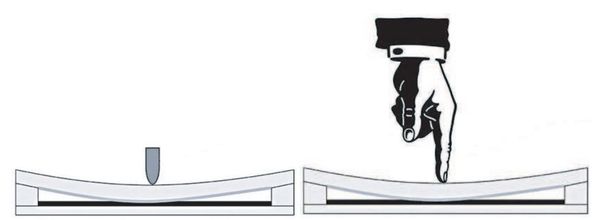
Thinpot is another sensor which is directly available in the market. It works on the same principle of variable resistance. It is nothing but the potentiometer which can be arced and pasted to curved surfaces. It has three terminals, two for supply, ground and one for measuring variable resistance. We have to use external wiper which traverse over the thinpot and resistance gets changed at pin 2 of the wiper. The total resistance of thinpot is 10KΩ which changes as wiper moves. We used this sensor as it has no restrictions over power supply voltage, easy to attach to bike, and easy to get readings using ADC.
Hall Effect Sensor
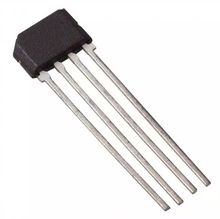
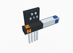
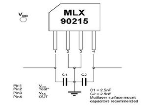
A Hall effect sensor is a sensor that varies its output voltage in response to a magnetic field. Hall effect sensors are used for proximity switching, positioning, speed detection, and current sensing applications. The sensor operates as an analog transducer, directly returning a voltage. There three types of hall effect sensors, hall effect switch, hall effect latch and hall effect linear sensor. Hall effect switch turns on in the presence of a magnetic field. Hall effect latch holds its current state until the opposite polarity changes its state. Hall effect linear sensor varies its output voltage in proportional to the strength of the magnetic field near to it. In the absence of magnetic field, linear sensor output voltage is approximately 2.5V. When the south pole comes closer to the sensor, its output increases proportionally towards 5V. Its output voltage decreases towards 0V, when north pole is brought closer to the sensor. We used this property to to detect the turn angle direction. We designed our sensor arrangement such that a horizontal bar magnet attached to the handlebar and sensor to the bike frame. When a magnet moves with handlebar while taking turns, the output of the sensor varies. But the sensor MLX90215 which we used for this testing was not behaving as per the design. Its EEPROM needed to be programmed irs special programmer. After some testing, we decided to change our design and switched to thinpot.
Software Design & Implementation
Show your software design. For example, if you are designing an MP3 Player, show the tasks that you are using, and what they are doing at a high level. Do not show the details of the code. For example, do not show exact code, but you may show psuedocode and fragments of code. Keep in mind that you are showing DESIGN of your software, not the inner workings of it.
Implementation
This section includes implementation, but again, not the details, just the high level. For example, you can list the steps it takes to communicate over a sensor, or the steps needed to write a page of memory onto SPI Flash. You can include sub-sections for each of your component implementation.
Object Detection Sensor
Hardware Design
The distance sensors are used to detect the oncoming traffic from the back and to warn the rider about the traffic.The distance sensors' output will then be given to the voice module which will output the details to the biker in audio form.For the distance sensing we used the Maxbotix 1260 sensor.
Sensor Working
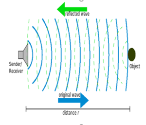
Maxbotix makes use of ultrasonic waves to sense the objects.The frequency used by these sensors in 42kHz sound waves.The frequency is selected
such that it is able to detect object regardless of its visual characteristics.The 42kHz frequency will not range through the solids.The main concept behind the ultrasonic sensors is that it sends the ultrasonic waves towards the objects.These waves when hit an object it gets reflected back from the object and the sensor sends an interrupt to the processor.
Bean Pattern
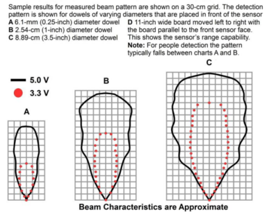
The sensor has a calibrated beam pattern.The diagram below shows the approximate beam pattern and the detection area.One can select the distance sensor matching their needs depending on the pattern and the range of the beam. The beam patterns help identify an estimated detection zone for an application based on the acoustic properties of a target versus the plotted beam patterns. Each beam pattern is a 2D representation of the detection area of the sensor. The beam pattern is actually shaped like a 3D cone (having the same detection pattern both vertically and horizontally).
Sensor Minimum Distance
The sensor minimum reported distance is 20cm (7.87 inches). However,the maxbotix ranges and reports targets to the front sensor face. Large targets closer than 20cm typically range as 20cm.
Software Design & Implementation
LED Strip
Hardware Design
Software Design & Implementation
Text to Speech IC
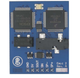
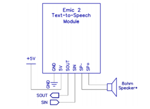
Hardware Design
Software Design And Implementation
Testing & Technical Challenges
PCB
In designing the PCB,we worked on EAGLE which was a whole new experience.Below listed are the major challenges faced by us:
- We found that the maximum size of the PCB could only be 10x5.5 inch as the software used is a freeware and hence it has its limitations.
- Common Ground: The board as a whole needs to be grounded. This means to avoid unwanted issues, the unused pins are grounded as well as the common ground needs to be taken care off. We were unfamiliar with the handling of ground initially as there is no direct connection or ground pin for the PCB. After careful understanding, we found the working of ground on the PCB.
- Missing Connections: The circuit once completed needs to be properly checked. We used auto Routing facility to connect the PCB connectors but found due to space constraint, the tool missed some ports unconnected. So before the final ordering, careful check of connections needs to be done.
- Ordering and soldering needs to be done carefully as per the package/device name of the connector used in the design.
- Soldering the micro USB component was extremely difficult since the pins were very small
Conclusion
This project was a success and the overall objectives of the project were met. The various sensors communicate seamlessly with the microcontroller and provide feedback to the cyclist via text-to-speech. The front headlight and back LEDs operate as we planned them to, the front headlight only turns on when it is dark outside and the appropriate back LED turn signals flash when the bicyclist is making turns. This project was exciting to work on since it incorporated so many various sensors and modules that had to interact together with the SJOne board. This project increased our knowledge in both software and hardware domain. We learned valuable lessons and had to overcome some difficulties with choosing the appropriate hardware for the Biker Assist project. Designing the PCB was a rewarding experience and it gave us confidence in our ability to design a PCB for a specific project.
Project Video
Project Source Code
References
Acknowledgement
Any acknowledgement that you may wish to provide can be included here.
References Used
List any references used in project.
http://www.cdc.gov/motorvehiclesafety/bicycle/
http://www.statista.com/topics/1448/bicycle-industry-in-the-us/
Appendix
You can list the references you used.
