S16: Biker Assist
Contents
Grading Criteria
- How well is Software & Hardware Design described?
- How well can this report be used to reproduce this project?
- Code Quality
- Overall Report Quality:
- Software Block Diagrams
- Hardware Block Diagrams
- Schematic Quality
- Quality of technical challenges and solutions adopted.
==
Biker Assist
Abstract
This section should be a couple lines to describe what your project does.
Objectives & Introduction
Show list of your objectives. This section includes the high level details of your project. You can write about the various sensors or peripherals you used to get your project completed.
Team Members
Roles and Responsibilities
- Adnan Dzebic & Nitesh Jain
- LED Strip Design
- PCB Design
- Urvashi Agarwal
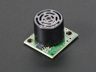
- Distance Sensor Design
- Amit Pachore
- Turn Angle Sensor Design
- Text-to-Speech Module
- 3D Designs
Project Schedule
| Sr. No. | Start Date | End Date | Task | Status | Actual Completion Date |
|---|---|---|---|---|---|
| 1 | 03/22/2016 | 03/28/2016 | Ordering the components | Completed | 04/02/2016 |
| 2 | 03/22/2016 | 04/04/2016 | Reading data sheet and understanding the components | Completed | 04/04/2016 |
| 3 | 03/29/2016 | 04/15/2016 | Algorithm design and Coding | Completed | 04/15/2016 |
| 4 | 04/15/2016 | 04/25/2016 | Distance sensor interfacing and Testing | Completed | 05/01/2016 |
| 5 | 04/15/2016 | 04/25/2016 | Automatic light interfacing and testing | ||
| 6 | 04/26/2016 | 05/02/2016 | Integrating and testing | ||
| 7 | 05/03/2016 | 05/16/2016 | Testing and adding extra features | ||
| 8 | 05/17/2016 | 05/23/2016 | Final testing and Demo |
Parts List & Cost
Give a simple list of the cost of your project broken down by components. Do not write long stories here.
Design & Implementation
The design section can go over your hardware and software design. Organize this section using sub-sections that go over your design and implementation.
Turn Angle Detection Sensor
Hardware Design
A turn angle detection sensor is used to detect the exact measure of turn of the bike handlebar. This angle measurement is used to determine if the bike is taking turns. This sensor design has two different approaches. These are varying resistance approach and hall effect approach. Finally, we settled on using thinpot which works on the varying resistance approach. These two methods are explained below.
Varying Resistance Sensor
This sensor functions using the principle of Ohm's law. This law dictates that the current is inversely proportional to resistance for a given voltage. The sensor has three terminals, two end points for connecting voltage across sensor and one middle terminal called wiper. As the wiper terminal traverse over the coil, sensor gives varying resistance across wiper and one of the other terminals and hence varying voltage. Varying voltage output pin is connected to the ADC of the micro-controller and exact turn angle can be determined. We worked on two different sensors working on this principle.
Custom Resistance Coil
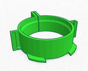
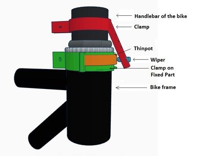
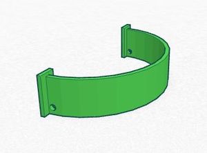
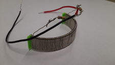
To detect turn angle, we designed our custom coil. We wound high resistance wire on a semicircular base to look like a coil. This coil was attached to the fixed part of the bicycle. The third terminal acting as a wiper was attached to the moving part of the handlebar such that, it traverses over the coil. We attached two resistances of value 10K were attached before connecting to the battery. These two circuits formed a potential divider circuit and also avoided battery short circuit.
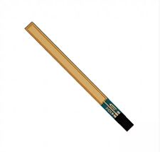
Thinpot
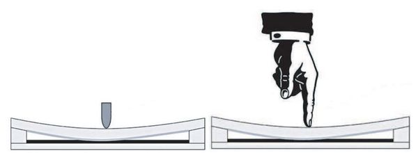
Thinpot is another sensor which is directly available in the market. It works on the same principle of variable resistance. It is nothing but the potentiometer which can be arced and pasted to curved surfaces. It has three terminals, two for supply, ground and one for measuring variable resistance. We have to use external wiper which traverse over the thinpot and resistance gets changed at pin 2 of the wiper. The total resistance of thinpot is 10KΩ which changes as wiper moves. We used this sensor as it has no restrictions over power supply voltage, easy to attach to bike, and easy to get readings using ADC.
Hall Effect Sensor
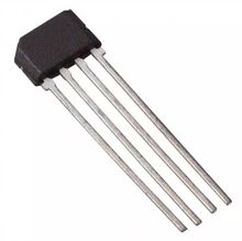
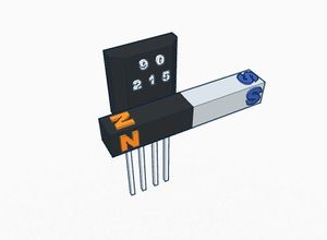
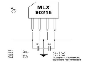
A Hall effect sensor is a sensor that varies its output voltage in response to a magnetic field. Hall effect sensors are used for proximity switching, positioning, speed detection, and current sensing applications. The sensor operates as an analog transducer, directly returning a voltage. There three types of hall effect sensors, hall effect switch, hall effect latch and hall effect linear sensor. Hall effect switch turns on in the presence of a magnetic field. Hall effect latch holds its current state until the opposite polarity changes its state. Hall effect linear sensor varies its output voltage in proportional to the strength of the magnetic field near to it. In the absence of magnetic field, linear sensor output voltage is approximately 2.5V. When the south pole comes closer to the sensor, its output increases proportionally towards 5V. Its output voltage decreases towards 0V, when north pole is brought closer to the sensor. We used this property to to detect the turn angle direction. We designed our sensor arrangement such that a horizontal bar magnet attached to the handlebar and sensor to the bike frame. When a magnet moves with handlebar while taking turns, the output of the sensor varies. But the sensor MLX90215 which we used for this testing was not behaving as per the design. Its EEPROM needed to be programmed irs special programmer. After some testing, we decided to change our design and switched to thinpot.
Software Design & Implementation
Show your software design. For example, if you are designing an MP3 Player, show the tasks that you are using, and what they are doing at a high level. Do not show the details of the code. For example, do not show exact code, but you may show psuedocode and fragments of code. Keep in mind that you are showing DESIGN of your software, not the inner workings of it.
Implementation
This section includes implementation, but again, not the details, just the high level. For example, you can list the steps it takes to communicate over a sensor, or the steps needed to write a page of memory onto SPI Flash. You can include sub-sections for each of your component implementation.
Object Detection Sensor
Hardware Design
Software Design & Implementation
LED Strip
Hardware Design
Software Design & Implementation
Testing & Technical Challenges
Describe the challenges of your project. What advise would you give yourself or someone else if your project can be started from scratch again? Make a smooth transition to testing section and described what it took to test your project.
Include sub-sections that list out a problem and solution, such as:
My Issue #1
Discuss the issue and resolution.
Conclusion
Conclude your project here. You can recap your testing and problems. You should address the "so what" part here to indicate what you ultimately learnt from this project. How has this project increased your knowledge?
Project Video
Upload a video of your project and post the link here.
Project Source Code
References
Acknowledgement
Any acknowledgement that you may wish to provide can be included here.
References Used
List any references used in project.
Appendix
You can list the references you used.
