S16: Warriors
Contents
Wifi based sensor system
This is an IoT based sensor system which allows sensor data to be accessed over the internet from anywhere.
Abstract
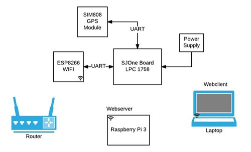
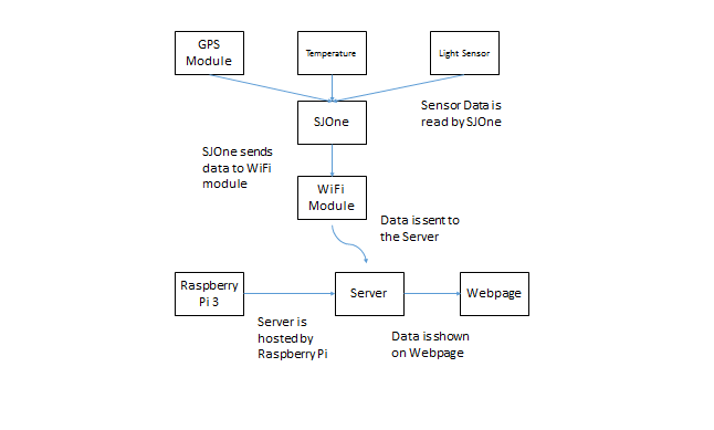
The most basic aspect of an IoT system is the network of devices/objects. IoT allows objects to be sensed and controlled remotely across existing network infrastructure. This project is based on the same fundamental. SJOne board senses temperature, light intensity, and GPS (SIM800) module. WiFi capability is added to SJOne board using ESP8266 serial module. SJOne(client) transmits the sensor data over the network to the server. Raspberry Pi 3 acts as a server, receives the data from the client and stores it in mysql database. A php webpage takes the most recent entry from database and displays on the webpage along with map.
Objectives
1) Set up sensor hub:
- Interface GPS module with SJOne
- Write drivers to access the temperature and light intensity sensors on-board SJOne
2) Set up TCP Client:
- Interface the WiFi module with SJOne board and implement a TCP client
- Write device driver to transmit data from SJOne client to the server
3) Set up TCP Server:
- Use Raspberry Pi 3 to work as a TCP server to receive data from client
- Create a database to keep a record of previously acquired data
4) Set up Webserver:
- Start the web server and host a web page
Team Members & Responsibilities
Ankit Gandhi
--> Software Architecture, Raspberry Pi setup, ESP8266 firmware development
Bharat Khanna
--> Device driver development for SIM808/ESP8266 for ARM microcontroller, PCB designing
Sujeeth Emmadi
--> Software Architecture, Wiki Report, PHP web server
Veena Manasa Kanakamalla
--> Wiki Report, Sensor interface, Hardware Support
Schedule
| SI No. | Start Date | End Date | Task | Status | Actual Completion Date |
|---|---|---|---|---|---|
| 1 | 03/21/2016 | 03/27/2016 |
|
Completed | 03/27/2016 |
| 2 | 03/28/2016 | 04/03/2016 |
|
Completed | 04/03/2016 |
| 3 | 04/04/2016 | 04/10/2016 |
|
Completed | 04/10/2016 |
| 4 | 04/11/2016 | 04/17/2016 |
|
Completed | 04/20/2016 |
| 5 | 04/18/2016 | 04/24/2016 |
|
Completed | 04/24/2016 |
| 6 | 04/25/2016 | 05/01/2016 |
|
Completed | 05/01/2016 |
| 7 | 05/02/2016 | 05/08/2016 |
|
Completed | 05/08/2016 |
| 8 | 05/09/2016 | 05/15/2016 |
|
Completed | 05/20/2016 |
| 8 | 05/16/2016 | 05/22/2016 |
|
Completed | 05/23/2016 |
Parts List & Cost
| Item# | Part Description | Vendor | Qty | Cost |
|---|---|---|---|---|
| 1 | Raspberry Pi | Adafruit | 1 | $39.95 |
| 2 | ESP8266-Wifi Module | Adafruit | 1 | $9.95 |
| 3 | SIM808 GPS/GSM Module | Adafruit | 1 | $49.95 |
| 4 | Passive GPS Antenna uFL | Adafruit | 1 | $3.95 |
| 5 | USB to TTL Serial Cable | Adafruit | 1 | $9.95 |
Design & Implementation
System Block Diagram
Components
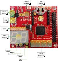
SJOne Board
- Powered by ARM Cortex-M3
- On board Temperature Sensor and light sensor.
- Many GPIOs with two SPI, Multiple UARTs, and I2C availability.
- Power from USB or External Power.
The SJOne board offers whole lot of features out of which the temperature sensor, light intensity sensor and UART interfaces are utilized for the project.
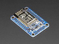
The WiFi Module - ESP8266
The features of ESP8266 are:
- 1 x Analog input (1.8V max)
- 9 x GPIO (3.3V logic), which can also be used for I2C or SPI
- 2 x UART pins
- 2 x 3-12V power inputs, reset, enable, LDO-disable, 3.3V output
We have used UART for communication in our project.
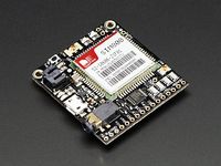
SIM808 GPS Module
SIM 808 MiniGSM + GPS, an all-in-one cellular phone module which provides location-tracking, voice, text, SMS and data facilities
- Quad-band 850/900/1800/1900MHz
- AT command interface with "auto baud" detection
- 22 tracking / 66 acquisition channels
- Sensitivity: Tracking: -165 dBm, Cold starts : -147 dBm
- Accuracy: approx 2.5 meters
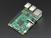
Raspberry Pi 3
- A 1.2GHz 64-bit quad-core ARMv8 CPU with 1 GB RAM
- On board 802.11n Wireless LAN
- 40 GPIO pins and many serial interfaces
- Micro SD card slot
- On board chip antenna for radio
The Raspberry Pi 3 is the third generation Raspberry Pi. In this project raspberry pi is used as webserver.
Hardware Interface
The hardware design includes PCB designing using cadsoft Eagle(software for PCB board designing). The circuit design of PCB includes SIM808(GSM/GPS module) and ESP826( Wi-Fi module) which is connected to ARM cortex-M3 microcontroller. Onboard sensors of SJOne board like TEMT6000X01(light sensor) and TMP102(temperature sensor) are also used to collect data. I2C, UART and TCP/IP are the three communication protocols that are being used in the project for establishing communication of temperature/light sensor, SIM808/ESP8266 & raspberry pi with ARM microcontroller respectively.
ESP8266 interface with SJOne
The WiFi module(ESP8266) is interfaced with the SJOne board(ARM microcontroller) using UART3 bus. Pin number p4.28 and p4.29 is used as RX and TX respectively.
SIM808 GPS Module Interface with SJOne
The SIM808 module is interfaced with SJOne using UART protocol. The Transmit and Receive pins of the GPS module are connected to UART2 of SJOne. RX pin of GPS is connected to pin P2.8 of SJOne board (TX) and TX pin of GPS is connected to pin P2.9 of SJOne (RX).
Software Design & Implementation
- System consists of two entities. A client and a server.
Client
On the Client side, SJOne(ARM Cortex-M3) is interfaced with the sensors(temperature, light, latitude, longitude, time etc). It collects the data from sensors at regular interval and sends the received data to the server over WiFi.
The client software is written on FreeRTOS using C/C++, including features of real-time embedded system, which is implemented using two tasks.
sensorTask
- This task takes sensor readings at regular intervals (3 milliseconds) (light, temperature, time, latitude, longitude, and time) and stores in a structure
- And then calls the semaphoregive API which signals the higher priority WiFi task.
wifitask (Higher priority task than sensor task)
- In the initialization it configures the ESP8266 for WiFi communication and connects to a predefined WiFi network and the server.
- Then it waits for the semaphore from sensor task. Once signaled by sensor task, sends the data to the server.
Pseudo code for client
sensorTask() {
:readSensorData();
:xSemaphoreGive();
:delay();
}
wifiTask() {
:xSemaphoreTake();
:sendData();
}
main() {
:xSemaphoreCreateBinary();
:addtask(sensorTask, medium_priority);
:addtask(wifiTask, high_priority);
:start_scheduler();
}
Server
Raspberry pi is used as TCP and web server. TCP server listens for client connection request, once connected, the server reads the data and stores it into MySQL database. Then web server reads the latest sensor values from the database and displays on the web page and plots the latitude and longitude using google maps.
Environmet setup requires installation of apache, mysql and php on the board.
These commands can be used for installation
:sudo apt-get install apache2 -y
:sudo apt-get install php5 libapache2-mod-php5 -y
:sudo apt-get install php5-mysql
For Wifi network setup
pi@raspberrypi: sudo vim /etc/wpa_supplicant/wpa_supplicant.conf
And then put your ssid and password as follows
network={
:ssid="your_ssid"
:psk="password"
}
There are two modules on server side
TCP server
- TCP server connects to TCP client, receives the data and stores into the database.
- It is written in C. It uses TCP socket to accept client requests and receive the sensor data.
Web server
- Web server reads data from database and display on the web page. It is written in PHP.
- Google maps APIs are used latitude,longitude plotting.
Pseudo code for TCP server
main() {
:createsocket(socket);
:bind(socket);
:listen(socket);
:accept(socket);
:readData(socket);
:insertDataMysqlDatabase();
}
Testing & Technical Challenges
- First and very important step in any project is requirement gathering.
- A good amount of time should be spent on Software and Hardware design. Once the on paper design is ready it makes the development phase very smooth.
- Once the development is done testing (individual and as a whole system ) also very important.
- Wifi client module can be tested usb to serial cable with PC. From PC terminal we can give the AT commands and check the responses. Further testing requires a TCP server, which can respond to the requests. This can be implemented using Hercules utility.
- GPS module can also be tested in the same manner using usb to serial cable with PC. From PC terminal we can give the AT commands and check the responses.
- From client side GET/POST query can be used which will eliminate the requirement of TCP server.
Issues
- LPC17xx UART Rx FIFO
- LPC17xx UART not able to receive more than 16 bytes
- Resolution :
- Used interrupt to solve this problem.
Conclusion
Facing issues such as UART FIFO size and power requirements, allowed us to understand that our knowledge over several aspects, when it came to depth, was lacking. Solving these problems, helped us understand those concepts better but, more importantly, we gained experience on how to approach situations where the project gets stuck.
The concepts that we have worked on, and now understand better, in this project are:
- Setting up TCP server-clients
- Interfacing sensors using UART
- Configuration of Interrupts
- Understanding WiFi technology
- Making use of AT commands
- Socket Programming
Project Video
Project Source Code
Visit this link Sourceforge
