S17: Sky Knight
Contents
Grading Criteria
- How well is Software & Hardware Design described?
- How well can this report be used to reproduce this project?
- Code Quality
- Overall Report Quality:
- Software Block Diagrams
- Hardware Block Diagrams
- Schematic Quality
- Quality of technical challenges and solutions adopted.
Sky Knight
Abstract
We aimed to implement a Quadcopter capable of self-sustained flight. Our quadcopter had 4 arms with propeller and motors on each. The propellers generate thrust that lifted the quadcopter. ESC(Electronic Speed Control ) were used to control the motor rotation speed depending on PWM provided from SJOne. We implemented the self-stabilizing technique using PID algorithm. Android Application is also developed to provide user interface to control the motion of Quadcopter. The communication between app and SJOne will be done using Bluetooth.
Objectives
The main objective of this project is to implement the following.
- Design and build an efficient hardware so that it is easy to mount on Quadcopter.
- Interface the BNO055 sensor with LPC1758 to get pitch, roll and yaw angles.
- Develop Android Application to control the motion of the quadcopter and communicate with SJOne via Bluetooth.
- Analyze PID algorithms and tune the PID algorithm that will stabilize the flight of Quadcopter.
Introduction
Team Members & Responsibilities
Schedule
| Sr. No | Start Date | End Date | Task | Status | Actual Completion Date |
|---|---|---|---|---|---|
| 1 | 2/21/2017 | 2/28/2017 |
|
Completed | 2/28/2017 |
| 2 | 2/28/2017 | 3/14/2017 |
|
Completed | 3/14/2017 |
| 3 | 3/14/2017 | 3/28/2017 |
|
Completed | 3/29/2017 |
| 4 | 3/14/2017 | 4/11/2017 |
|
Completed | 4/15/2017 |
| 5 | 4/11/2017 | 4/25/2017 |
|
Completed | 4/25/2017 |
| 6 | 4/15/2017 | 4/25/2017 |
|
Completed | 4/18/2017 |
| 7 | 4/25/2017 | 5/01/2017 |
|
In Progress | |
| 8 | 5/2/2017 | 5/8/2017 |
|
||
| 9 | 5/9/2017 | 5/15/2017 |
|
Parts List & Cost
Give a simple list of the cost of your project broken down by components. Do not write long stories here.
| Qty | Description | Manufacturer | Part Number | Total Cost |
|---|---|---|---|---|
| 1 | FPV 4-Axis Quadcopter Frame kit w/ Protective Guard | UFO | $41.00 | |
| 1 | Adafruit 9-DOF Sensor | Adafruit | BNO055 | $39.97 |
| 1 | Quadcopter Power Distribution Board | Hobby King | $10.00 | |
| 1 | PCB | PCBWay | $27.00 | |
| 4 | OPTO Brushless ESC | ARRIS 2-6S 30AMP | $53.00 | |
| 4 | 6045 Carbon Nylon Propellers | Gemfan | $4.00 | |
| 1 | SJOne Board | Preet | LPC1758 SJSU Board | $80.00 |
| 1 | x2204 2300kv Brushless Motors - set of 4 | SunnySky | SNS-X2204S-KV2300 | $63.00 |
| 2 | 4000mAh 3S 30C Lipo Battery Pack | Turnigy | T4000.3S.30 | $22.00 |
| 1 | 50W 5A Balancer Charger | Hobbyking | ECO6 | $19.00 |
| 1 | 105W 15V/7A DC power supply | Hobbyking | 9052000023-3 | $15.00 |
| 1 | 3.5mm Gold Connectors | Polymax | $2.00 | |
| 1 | Long Nylon Threaded Spacers | $6.00 | ||
| 1 | Test Environment Frame for testing | Home Depot | $15.00 | |
| Total Cost (excluding shipping and taxes) | $397.00 |
Design & Implementation
Hardware Design
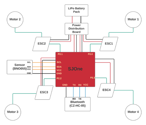
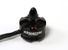
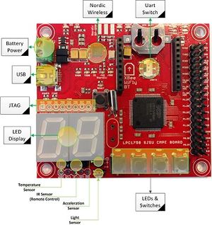
For making of quadcopter a SJOne board is used on which flight controlling software was implemented. This board reads the value from the BNO055 sensor and generates the PWM (Pulse Width Modulation) pulse to drive the four motors. In this project we used four 2300KV SunnySky brushless servo motor are used. 2300 KV means that for each one volt applied to motor it will produce an RPM of 2300.
To make the quadcopter a SJOne board is used on which the flight controller software is developed. This board reads the sensors values and generates the PWM (Pulse Width Modulation) pulses to drive the four motors.
In this project four KV2300 Sunnysky brushless servo motors are used. 2300KV means that for each one volt applied to the motor it will produce an RPM of 2300. The battery used in this project is 3cell 11.8V which roughly produces 27k rpm.
Motors
We have implemented Brushless motors for our quadcopter. They are much more powerful and energy efficient, unlike DC motors. The kV rating on the motor indicates how many RPM the motor can rotate for the given number of volts. Brushless motors work by producing magnetic fields to produce electric charges. The speed of the spinning motor is controlled by an ESC. In our Quadcopter we have 2 motors on the diagonals moving in clockwise while the other two in anti-clockwise.
Electronic Speed Controller (ESC)
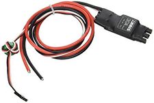
We have used ESC (Electronic Speed Control) to control the motor rotation speed also to set its direction (clockwise or anti-clockwise ).The ESC will control the PWM values provided to it by LPC 1758 board. Our ESC runs at about 400 Hz with pulse widths that range from 3.12ms to 6.25 ms. 3.12 ms turns off the motor input while 6.25 ms makes the motor run at max speed. The OPTO brushless ESC is programmable, and has several different parameters for the user to configure.
Sensor
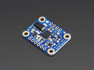
The BNO055 is a sensor that measures the orientation of the quadcopter. Sensor is important because it provide the necessary information needed to control the quadcopter. Included in the Sensor is an accelerometer, a gyroscope, and a magnetometer. This device is connected to SJOne to calculate the PID values for the yaw, pitch and roll. In our case, Y points to the north by default. The SJSUOne board reads these values and adjusts the quadcopter accordingly.
SJOne Flight Controller
The SJOne board is programmed and configured to be the flight controller of the quadcopter. The RC receiver, the sensor, and the ESC are all hooked up to the board. Each of these devices are actively working together and are controlled by the board. The receiver takes input from the RC and outputs it into the SJOne board. The board will process the requested PWM and will use this information to control the ESC. It will also process the requested angle of pitch and roll. The sensor readings will be used to process both the requested angle from the RC, and to process the flight stabilization calculations. This microcontroller controls every aspect required for the quadcopter to fly. Every action must first go through the SJOne board. FreeRTOS is extensively used on the board. Many critical actions such as remote control and flight stabilization are set up as tasks. The board will determine the priority given to each task.
Hardware Interface
In this section, you can describe how your hardware communicates, such as which BUSes used. You can discuss your driver implementation here, such that the Software Design section is isolated to talk about high level workings rather than inner working of your project.
Software Design
Show your software design. For example, if you are designing an MP3 Player, show the tasks that you are using, and what they are doing at a high level. Do not show the details of the code. For example, do not show exact code, but you may show psuedocode and fragments of code. Keep in mind that you are showing DESIGN of your software, not the inner workings of it.
Implementation
This section includes implementation, but again, not the details, just the high level. For example, you can list the steps it takes to communicate over a sensor, or the steps needed to write a page of memory onto SPI Flash. You can include sub-sections for each of your component implementation.
Testing & Technical Challenges
Describe the challenges of your project. What advise would you give yourself or someone else if your project can be started from scratch again? Make a smooth transition to testing section and described what it took to test your project.
Include sub-sections that list out a problem and solution, such as:
My Issue #1
Discuss the issue and resolution.
Conclusion
Conclude your project here. You can recap your testing and problems. You should address the "so what" part here to indicate what you ultimately learnt from this project. How has this project increased your knowledge?
Project Video
Upload a video of your project and post the link here.
Project Source Code
References
Acknowledgement
Any acknowledgement that you may wish to provide can be included here.
References Used
List any references used in project.
Appendix
You can list the references you used.
