CAN CLAN
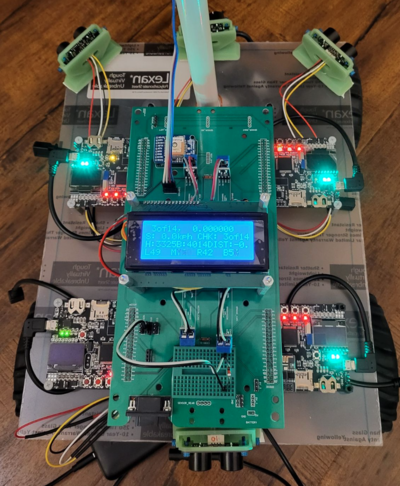
Picture of the RC Car
Abstract
Our goal for this project is to use knowledge we gathered from lectures to design, implement, and test a self-driving RC car using a Controller Area Network (CAN) bus for controller communication. The project involves FreeRTOS and utilizes periodic tasks (running at 1Hz, 10Hz, and 100Hz) to gather, process, and display data from various embedded modules.
Introduction
The project was divided into 5 modules:
Sensor Information
Motor Operation
Geological Information
Driver & LCD Manager
Bridge & Android Application
Team Members & Responsibilities
<Team Picture>
Gitlab Project Link - https://gitlab.com/rashmi_sv/the_CAN_clan.git

Rashmi Suhas Vaidya
- Geo Controller
- GPS and Compass Interfacing
- Driver Node
- Integration Testing
Zeel Jatinkumar Lia
- Sensor and Bridge Controller
- RPM Sensor
- Driver Node
- Integration Testing
Priyam Hajisheth
- Driver Node
- LCD interfacing
- Mobile App
- Integration Testing
Xinyu He
- Hardware solution
- Wiki Page Update
- Integration Testing
Hongjin Cheng
- RPM Sensor
- Motor Controller
- Hardware assembling
- Integration Testing
Schedule
| Week#
|
Start Date
|
End Date
|
Task
|
Status
|
| 1
|
03/01/2023
|
03/07/2023
|
- Read previous projects, gather information and discuss among the group members.
- Discuss each team-member's preference and assign controller roles
- Create parts list for the RC car, discuss, and decide on each item
|
|
| 2
|
03/08/2023
|
03/14/2023
|
- Order all parts from list and save tracking/price info
|
|
| 3
|
03/15/2023
|
03/21/2023
|
- Design interface for Bridge and Sensor Controller, with unit tests
- Design interface for Motor Controller, with unit tests
- Design interface for Driver and LCD Controller, with unit tests
- Integrate Bridge/Sensor Controller to CAN bus with DBC, handling messages
- Integrate Motor Controller to CAN bus with DBC, handling messages
- Integrate Driver Controller to CAN bus with DBC, handling messages
- All parts received
|
|
| 4
|
03/22/2023
|
03/28/2023
|
- Design interface for GEO Controller, with unit tests
- Integrate Geological Controller to CAN bus with DBC, handling messages
- Integrate Ultrasonic sensor with SJ2 to verify distance from obstacle is sensed
- Integrate Motor and Steering with PWM control, figure out the working ranges
- Integrate GPS sensor with SJ2, get GPGGA strings over UART, parse current coordinates
|
|
| 5
|
03/29/2023
|
04/04/2023
|
- Integrate Compass sensor with SJ2 board over I2C and get bearing values
- Connect all nodes together on the CAN bus, verify messages across all nodes
- Code the Haversine formula into GEO controller to get distance and heading based on current and destination coordinates
- Write driver logic based on distance and heading from GEO and obstacle details from sensor nodes
- Integrate GPS and Compass peripherals, writing the driver and unit tests
- MILESTONE - All individual modules considered "Roughly Working" with hardware interfaced
|
|
| 6
|
04/05/2023
|
04/11/2023
|
- Finalize the DBC file for project
- Create a detailed schedule for remaining tasks, dividing work into four milestones
- Start RPM sensor logic implementation and add it to Motor controller
- Integrate Bluetooth module to Bridge/Sensor controller, with UART logic
- Work on integrating the MaxBotix ultrasonic sensor with the sensor module
- Work on Stage-1 mounting of all components on the RC car with temporary fixing
- Fix problem with BDC-DBF conversion on BusMaster and show graphs on it
- MILESTONE - Basic car driving ability with basic obstacle avoidance
|
|
| 7
|
04/12/2022
|
04/18/2022
|
- Complete basic working Mobile App which connects to the bridge controller, sends a test message and receives sensor values
- Work on calibrating compass sensor to get accurate bearing readings
- Create a on-board battery power supply for all components
- Work on Stage-2 mounting of all components on the RC car with soldering of parts and wires
- Complete the Compass calibration and read accurate readings from it
- Have PWM signals reliably controlling the motor speed
- Start working on reliable navigation with obstacle avoidance
- MILESTONE - Integrated, reliably "heading" towards provided destination bearing, basic obstacle avoidance
|
|
| 8
|
04/19/2023
|
04/25/2023
|
- Send fake destination coordinates from Mobile app and start and stop commands
- Integrate LED display to the driver controller and show current heading, speed on it
- Add a GPS Lock LED on the Geo controller
- Add more LEDs on various SJ2 boards for more debug information for MIA, obstacle detection, etc
- Work on getting the car pass the Ramp test
- Work on Stage-3 permanent fixing of all components on the RC car
- Outdoor testing for longer range trips, and complete necessary enhancements
- MILESTONE - Integration part 2, perform obstacle avoidance and destination bearing
|
|
| 9
|
04/26/2023
|
05/02/2023
|
- Integrate Google Maps on Mobile App for destination coordinates
- Show debug information (GPS Coordinates, Sensor Values, Values from Compass, Calculated Distance, Motor Speed) on App and LED screen
- Work on getting the car to pass the U-turn test
- Verify that the electrical and mechanical work is complete
- MILESTONE - Integration and outdoor testing, adding necessary software changes
|
|
| 10
|
05/03/2023
|
05/09/2023
|
- Work on On/Off Button - power button to start the car
- Enable the Headlights to the car
- Work on robustness of the car, perform corner test cases in actual runs of the car
- Start working on report writing of the project
- MILESTONE - Integration testing, deal with uneven terrain, reliable waypoints navigation and obstacle avoidance
|
|
| 11
|
05/10/2023
|
05/16/2023
|
- Finish project report writing
- Full System Testing, any needed Hardware and software fixes and optimizing
|
|
| 11
|
05/24/2023
|
05/24/2023
|
|
|
Parts List & Cost
| Item#
|
Part Desciption
|
Vendor
|
Qty
|
Cost/Item
|
| 1
|
Unassembled RC Car
|
Traxxas [1]
|
1
|
$279.99
|
| 2
|
CAN Transceivers
|
Amazon [2]
|
4
|
$8.99
|
| 3
|
PCB
|
JLCPCB [3]
|
1
|
$40.00
|
| 4
|
Sensors
|
DFRobot [4]
|
4
|
$12.90
|
| 5
|
GPS
|
Amazon [5]
|
1
|
$29.92
|
| 6
|
RPM Sensor
|
Traxxas [6]
|
1
|
$19.00
|
| 7
|
WT901 IMU
|
Amazon[7]
|
1
|
$32.00
|
| 8
|
1kΩ Pull-Up Resistor
|
N/A
|
1
|
N/A
|
Printed Circuit Board
The preliminary design consisted of neatly routes wires on a breadboard connecting all the various components. It still looked confusing due to the sheer amount of connections that had to be made, this complexity was to be handled by a custom PCB designed in EasyEDA.
CAN Communication
<Talk about your message IDs or communication strategy, such as periodic transmission, MIA management etc.>
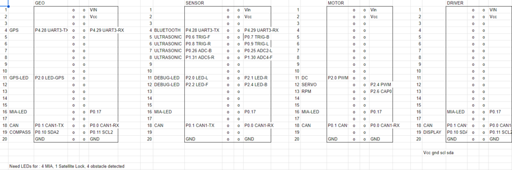
Hardware Design
<Show your CAN bus hardware design>
DBC File
Gitlab link to our DBC file :
https://gitlab.com/rashmi_sv/the_CAN_clan/-/blob/dev/dbc_file/dbc/project.dbc
<You can optionally use an inline image>
Sensor ECU
<Picture and link to Gitlab>
Hardware Design
Software Design
<List the code modules that are being called periodically.>
Technical Challenges
< List of problems and their detailed resolutions>
Motor ECU
<Picture and link to Gitlab>
Hardware Design
Software Design
<List the code modules that are being called periodically.>
Technical Challenges
< List of problems and their detailed resolutions>
Geographical Controller
<Picture and link to Gitlab>
Hardware Design
Software Design
<List the code modules that are being called periodically.>
Technical Challenges
< List of problems and their detailed resolutions>
Communication Bridge Controller & LCD
<Picture and link to Gitlab>
Hardware Design
Software Design
<List the code modules that are being called periodically.>
Technical Challenges
< List of problems and their detailed resolutions>
Master Module
<Picture and link to Gitlab>
Hardware Design
Software Design
<List the code modules that are being called periodically.>
Technical Challenges
< List of problems and their detailed resolutions>
Mobile Application
<Picture and link to Gitlab>
Hardware Design
Software Design
<List the code modules that are being called periodically.>
Technical Challenges
< List of problems and their detailed resolutions>
Conclusion
<Organized summary of the project>
<What did you learn?>
Project Video
Project Source Code
Advise for Future Students
<Bullet points and discussion>
Acknowledgement
=== References ===

