S23: CAN CLAN
Contents
CAN CLAN
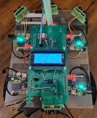
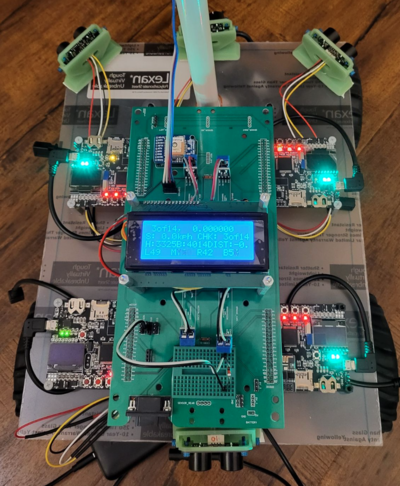
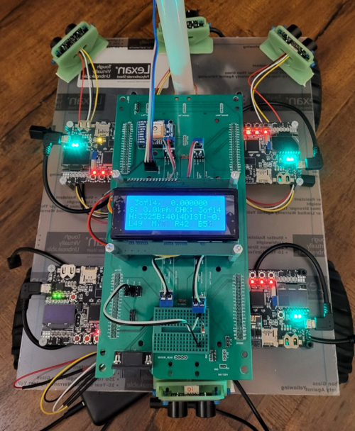
Picture of the RC Car
Abstract
Our goal for this project is to use knowledge we gathered from lectures to design, implement, and test a self-driving RC car using a Controller Area Network (CAN) bus for controller communication. The project involves FreeRTOS and utilizes periodic tasks (running at 1Hz, 10Hz, and 100Hz) to gather, process, and display data from various embedded modules.
Introduction
The project was divided into 5 modules:
- Sensor Information
- Motor Operation
- Geological Information
- Driver & LCD Manager
- Bridge & Android Application
Team Members & Responsibilities
<Team Picture>
Gitlab Project Link - https://gitlab.com/rashmi_sv/the_CAN_clan.git

Rashmi Suhas Vaidya
- Geo Controller
- GPS and Compass Interfacing
- Driver Node
- Integration Testing

Zeel Jatinkumar Lia
- Sensor and Bridge Controller
- RPM Sensor
- Driver Node
- Integration Testing

Priyam Hajisheth
- Driver Node
- LCD interfacing
- Mobile App
- Integration Testing

Xinyu He
- Hardware solution
- Wiki Page Update
- Integration Testing

Hongjin Cheng
- RPM Sensor
- Motor Controller
- Hardware assembling
- Integration Testing
Schedule
| Week# | Start Date | End Date | Task | Status |
|---|---|---|---|---|
| 1 | 03/01/2023 | 03/07/2023 |
|
|
| 2 | 03/08/2023 | 03/14/2023 |
|
|
| 3 | 03/15/2023 | 03/21/2023 |
|
|
| 4 | 03/22/2023 | 03/28/2023 |
|
|
| 5 | 03/29/2023 | 04/04/2023 |
|
|
| 6 | 04/05/2023 | 04/11/2023 |
|
|
| 7 | 04/12/2022 | 04/18/2022 |
|
|
| 8 | 04/19/2023 | 04/25/2023 |
|
|
| 9 | 04/26/2023 | 05/02/2023 |
|
|
| 10 | 05/03/2023 | 05/09/2023 |
|
|
| 11 | 05/10/2023 | 05/16/2023 |
|
|
| 11 | 05/24/2023 | 05/24/2023 |
|
|
Parts List & Cost
| Item# | Part Desciption | Vendor | Qty | Cost/Item |
|---|---|---|---|---|
| 1 | Unassembled RC Car | Traxxas [1] | 1 | $279.99 |
| 2 | CAN Transceivers | Amazon [2] | 4 | $8.99 |
| 3 | PCB | JLCPCB [3] | 1 | $40.00 |
| 4 | Sensors | DFRobot [4] | 4 | $12.90 |
| 5 | GPS | Amazon [5] | 1 | $29.92 |
| 6 | RPM Sensor | Traxxas [6] | 1 | $19.00 |
| 7 | WT901 IMU | Amazon[7] | 1 | $32.00 |
| 8 | 1kΩ Pull-Up Resistor | N/A | 1 | N/A |
Printed Circuit Board
The preliminary design consisted of neatly routes wires on a breadboard connecting all the various components. It still looked confusing due to the sheer amount of connections that had to be made, this complexity was to be handled by a custom PCB designed in EasyEDA.
CAN Communication
<Talk about your message IDs or communication strategy, such as periodic transmission, MIA management etc.>
Hardware Design
<Show your CAN bus hardware design>
DBC File
Gitlab link to our DBC file : https://gitlab.com/rashmi_sv/the_CAN_clan/-/blob/dev/dbc_file/dbc/project.dbc
<You can optionally use an inline image> VERSION ""
NS_ : BA_ BA_DEF_ BA_DEF_DEF_ BA_DEF_DEF_REL_ BA_DEF_REL_ BA_DEF_SGTYPE_ BA_REL_ BA_SGTYPE_ BO_TX_BU_ BU_BO_REL_ BU_EV_REL_ BU_SG_REL_ CAT_ CAT_DEF_ CM_ ENVVAR_DATA_ EV_DATA_ FILTER NS_DESC_ SGTYPE_ SGTYPE_VAL_ SG_MUL_VAL_ SIGTYPE_VALTYPE_ SIG_GROUP_ SIG_TYPE_REF_ SIG_VALTYPE_ VAL_ VAL_TABLE_
BS_:
BU_: DRIVER MOTOR SENSOR GEO DEBUG
BO_ 100 DRIVER_HEARTBEAT: 3 DRIVER
SG_ DRIVER_HEARTBEAT_cmd : 0|8@1+ (1,0) [0|0] "" DBG
BO_ 110 DRIVER_STEERING: 3 DRIVER
SG_ DRIVER_STEERING_yaw : 0|12@1+ (0.001,-2) [-10|10] "radians" MOTOR
SG_ DRIVER_STEERING_velocity : 12|12@1+ (0.01,-20) [-20|20] "kph" MOTOR
BO_ 120 MOTOR_HEARTBEAT: 5 MOTOR
SG_ MOTOR_HEARTBEAT_speed_raw : 0|8@1+ (1,0) [0|0] "count" DEBUG
SG_ MOTOR_HEARTBEAT_speed_rpm : 8|10@1+ (1,0) [0|0] "rpm" DEBUG
SG_ MOTOR_HEARTBEAT_speed_kph : 18|10@1+ (0.1,-10) [-10|10] "kph" DEBUG
SG_ MOTOR_HEARTBEAT_angle_duty : 28|10@1+ (0.001,-2) [-10|10] "duty" MOTOR
BO_ 125 MOTOR_DEBUG: 8 MOTOR
SG_ MOTOR_DEBUG_speed_target : 0|26@1+ (0.1,-10) [-10|10] "kph" DEBUG
SG_ MOTOR_DEBUG_speed_kph : 26|10@1+ (0.1,-10) [-10|10] "kph" DEBUG
SG_ MOTOR_DEBUG_speed_duty : 36|10@1+ (0.1,0) [0|0] "duty" DEBUG
SG_ MOTOR_DEBUG_integral_error : 46|10@1+ (0.1,-10) [-10|10] "error" DEBUG
SG_ MOTOR_DEBUG_current_state : 56|3@1+ (1,0) [0|5] "state" DEBUG
SG_ MOTOR_DEBUG_next_state : 59|3@1+ (1,0) [0|5] "state" DEBUG
BO_ 128 MOTOR_ESC_CALIBRATED: 1 MOTOR
SG_ MOTOR_ESC_CALIBRATED_calibration_status : 0|4@1+ (1,0) [0|3] "esc_calibration_e" DRIVER
SG_ MOTOR_ESC_CALIBRATED_start_calibration_ack_to_driver : 4|1@1+ (1,0) [0|1] "bool" DRIVER
BO_ 129 DRIVER_START_ESC_CALIBRATION: 1 DRIVER
SG_ MOTOR_ESC_CALIBRATED_begin_esc_calibration : 0|1@1+ (1,0) [0|3] "bool" MOTOR
BO_ 130 MOTOR_ACK: 1 MOTOR
SG_ MOTOR_ACK_cmd : 0|8@1+ (1,0) [0|0] "" DRIVER
BO_ 200 SENSOR_SONARS: 8 SENSOR
SG_ SENSOR_SONARS_left : 0|10@1+ (1,0) [0|800] "inch" DRIVER
SG_ SENSOR_SONARS_right : 10|10@1+ (1,0) [0|0] "inch" DRIVER
SG_ SENSOR_SONARS_middle : 20|10@1+ (1,0) [0|0] "inch" DRIVER
SG_ SENSOR_SONARS_back : 30|10@1+ (1,0) [0|0] "inch" DRIVER
SG_ SENSOR_SONARS_frame_id : 42|16@1+ (1,0) [0|0] "" DRIVER
BO_ 210 SENSOR_DESTINATION_LOCATION: 8 SENSOR
SG_ SENSOR_DESTINATION_latitude : 0|28@1+ (0.000001,-90.000000) [-90|90] "Degrees" GEO
SG_ SENSOR_DESTINATION_longitude : 28|28@1+ (0.000001,-180.000000) [-180|180] "Degrees" GEO
BO_ 218 NAVIGATION_MESSAGE: 1 GEO
SG_ NAVIGATION_STATUS_navigation_status : 0|8@1+ (1,0) [0|3] "navigation_status_e" DRIVER
BO_ 219 CHECKPOINT_MESSAGE: 8 GEO
SG_ CHECKPOINT_MESSAGE_compass_heading : 0|12@1+ (1,0) [0|359] "Degrees" DRIVER
SG_ CHECKPOINT_MESSAGE_destination_bearing : 12|12@1+ (1,0) [0|359] "Degrees" DRIVER
SG_ CHECKPOINT_MESSAGE_destination_distance : 24|16@1+ (0.1,0) [0|0] "Meters" DRIVER
SG_ CHECKPOINT_MESSAGE_curr_checkpoint_num : 40|8@1+ (1,0) [0|255] "Integer" DRIVER
SG_ CHECKPOINT_MESSAGE_total_checkpoint_num : 48|8@1+ (1,0) [0|255] "Integer" DRIVER
SG_ CHECKPOINT_MESSAGE_checkpoint_status : 56|8@1+ (1,0) [0|3] "checkpoint_status_e" DRIVER
BO_ 220 GEO_STATUS: 8 GEO
SG_ GEO_STATUS_compass_heading : 0|12@1+ (1,0) [0|359] "Degrees" DRIVER
SG_ GEO_STATUS_destination_bearing : 12|12@1+ (1,0) [0|359] "Degrees" DRIVER
SG_ GEO_STATUS_destination_distance : 24|16@1+ (0.1,0) [0|0] "Meters" DRIVER
BO_ 520 DEBUG_GPS_CURRENT_LOCATION: 8 GEO
SG_ DEBUG_GPS_CURRENT_LOCATION_latitude : 0|28@1+ (0.000001,-90.000000) [-90|90] "Degrees" DEBUG
SG_ DEBUG_GPS_CURRENT_LOCATION_longitude : 28|28@1+ (0.000001,-180.000000) [-180|180] "Degrees" DEBUG
SG_ DEBUG_GPS_CURRENT_LOCATION_fix : 56|2@1+ (1,0) [0|2] "" DEBUG
BO_ 521 DEBUG_GEO_GPS_UPDATE: 8 GEO
SG_ DEBUG_GEO_GPS_UPDATE_count : 0|16@1+ (1,0) [0|0] "" DEBUG
SG_ DEBUG_GEO_GPS_UPDATE_max_period : 16|16@1+ (1,0) [0|0] "milliseconds" DEBUG
SG_ DEBUG_GEO_GPS_UPDATE_min_period : 32|16@1+ (1,0) [0|0] "milliseconds" DEBUG
SG_ DEBUG_GEO_GPS_UPDATE_average_period : 48|16@1+ (1,0) [0|0] "milliseconds" DEBUG
BO_ 522 DEBUG_GEO_COMPASS_UPDATE: 8 GEO
SG_ DEBUG_GEO_COMPASS_UPDATE_count : 0|16@1+ (1,0) [0|0] "" DEBUG
SG_ DEBUG_GEO_COMPASS_UPDATE_max_period : 16|16@1+ (1,0) [0|0] "milliseconds" DEBUG
SG_ DEBUG_GEO_COMPASS_UPDATE_min_period : 32|16@1+ (1,0) [0|0] "milliseconds" DEBUG
SG_ DEBUG_GEO_COMPASS_UPDATE_average_period : 48|16@1+ (1,0) [0|0] "milliseconds" DEBUG
CM_ BU_ DRIVER "The driver controller driving the car"; CM_ BU_ MOTOR "The motor controller of the car"; CM_ BU_ SENSOR "The sensor controller of the car"; CM_ BU_ GEO "the geographical controller of the car"; CM_ BU_ DEBUG "the debug topic that all controllers can publish to"; CM_ BO_ 100 "Sync message used to synchronize the controllers"; CM_ SG_ 100 DRIVER_HEARTBEAT_cmd "Heartbeat command from the driver";
BA_DEF_ "BusType" STRING ; BA_DEF_ BO_ "GenMsgCycleTime" INT 0 0; BA_DEF_ SG_ "FieldType" STRING ;
BA_DEF_DEF_ "BusType" "CAN"; BA_DEF_DEF_ "FieldType" ""; BA_DEF_DEF_ "GenMsgCycleTime" 0;
BA_ "GenMsgCycleTime" BO_ 100 1000; BA_ "GenMsgCycleTime" BO_ 200 50; BA_ "FieldType" SG_ 100 DRIVER_HEARTBEAT_cmd "DRIVER_HEARTBEAT_cmd";
VAL_ 100 DRIVER_HEARTBEAT_cmd 2 "DRIVER_HEARTBEAT_cmd_REBOOT" 1 "DRIVER_HEARTBEAT_cmd_SYNC" 0 "DRIVER_HEARTBEAT_cmd_NOOP" ;
</pre>
Sensor ECU
<Picture and link to Gitlab>
Hardware Design
Software Design
<List the code modules that are being called periodically.>
Technical Challenges
< List of problems and their detailed resolutions>
Motor ECU
<Picture and link to Gitlab>
Hardware Design
Software Design
<List the code modules that are being called periodically.>
Technical Challenges
< List of problems and their detailed resolutions>
Geographical Controller
<Picture and link to Gitlab>
Hardware Design
Software Design
<List the code modules that are being called periodically.>
Technical Challenges
< List of problems and their detailed resolutions>
Communication Bridge Controller & LCD
<Picture and link to Gitlab>
Hardware Design
Software Design
<List the code modules that are being called periodically.>
Technical Challenges
< List of problems and their detailed resolutions>
Master Module
<Picture and link to Gitlab>
Hardware Design
Software Design
<List the code modules that are being called periodically.>
Technical Challenges
< List of problems and their detailed resolutions>
Mobile Application
<Picture and link to Gitlab>
Hardware Design
Software Design
<List the code modules that are being called periodically.>
Technical Challenges
< List of problems and their detailed resolutions>
Conclusion
<Organized summary of the project>
<What did you learn?>
Project Video
Project Source Code
Advise for Future Students
<Bullet points and discussion>
Acknowledgement
=== References ===


