F15: Minion
Contents
- 1 Minion
- 2 Abstract
- 3 Objective
- 4 Team Members & Responsibilities
- 5 Project Schedule
- 6 Parts List & Cost
- 7 Car Framework and Components
- 8 CAN Design
- 9 Design & Implementation of Controllers
- 9.1 Motor and I/O Controller
- 9.2 Master Controller
- 9.3 Sensor Controller
- 9.4 Geographical Controller
- 9.5 Communication Bridge Controller and Android Application
- 9.6 Common Technical Challenges
- 10 Conclusion
- 11 References
Minion


Abstract
This report is a description of how we built a prototype of a self navigating car by deploying the learnings from our graduate course CMPE- 243 Embedded System Applications. The prime motive was to navigate the car, autonomously, from a source point to destination point incorporating the following key features
- Driving and steering with the help of DC and Servo motors
- Feedback based speed control
- Obstacle detection and thereby collision avoidance
- Navigation on a user specified path
- Diagnosis of pertinent values through a display feature
The Micro-controllers- ARM Cortex3 LPC1758, FreeRTOS(operating system) and a highly reliable communication bus namely CAN constitute the basic building blocks of the car. User interaction is achieved with the help of a dynamic Android application that communicates with the controller through bluetooth. GPS and compass together aid in navigating the car.

Objective
The main objective of this project is to design and develop a self driving car capable of navigating itself from its source point to a given destination provided by an Android application. The car should follow the given path with the help of GPS and compass in the Geo controller.The car should avoid obstacles in its path with the help of ultrasonic sensors.The Master controller should make decisions to drive the motor as it receives data from Sensor controller and Geo controller in real time.The Android application should communicate with the car via a wireless medium and display sensor data in real time.The IO module should display geo controller data and sensor data on a LCD.
Team Members & Responsibilities
Sensor Controller:-
Motor & I/0 Controller:-
Communication Bridge & Android Controller:-
Geographical Controller:-
Master Controller:-
Treasurer:-
Hardware:-
Project Schedule
| Sr. No | Start Date | End Date | Task | Status | Actual Completion Date |
|---|---|---|---|---|---|
| 1 | 9/22/2015 | 9/28/2015 | RC Car and important component buying | Completed | 9/28/2015 |
| 2 | 9/29/2015 | 10/6/2015 | 1) Algorithm and architecture 2) Setup of car and decision on CAN Id's |
Completed | 10/6/2015 |
| 3 | 10/7/2015 | 10/13/2015 | 1) Coding and final set-up of car 2) Successful communication of CAN bus. 3) Car in running position. |
Completed | 10/13/2015 |
| 4 | 10/14/2015 | 10/20/2015 | Controlling car via Motor Controller | Completed | 10/20/2015 |
| 5 | 10/21/2015 | 10/27/2015 | 1) LCD Display working and finalizing the data to be displayed on LCD module. 2) Sensor data gathering |
Completed | 10/27/2015 |
| 6 | 10/28/2015 | 11/30/2015 | Integration of all the modules into one | Completed | 12/05/2015 |
| 7 | 11/04/2015 | 11/30/2015 | Testing depending upon integrated module | Completed | 12/05/2015 |
| 8 | 11/18/2015 | 11/30/2015 | Testing of Car and testing the self driving capability | Completed | 12/05/2015 |
| 9 | 11/25/2015 | 12/1/2015 | Testing of Car | Completed | 12/15/2015 |
Parts List & Cost
| Sr. No | Part Name | Source of Purchase | Part Number | Quantity | Cost($) |
|---|---|---|---|---|---|
| 1 | RC Car | Sheldons Hobbies | 360541 Stampede RTR | 1 | 239.99 |
| 2 | Battery | Sheldons Hobbies | VEN1548 - 5000NiMh 7.2 V | 1 | 44.99 |
| 3 | Traxx AC Adaptor | Sheldons Hobbies | TRAXXAS 2976 AC Adaptor to 12V | 1 | 24.99 |
| 4 | Compass | Amazon.com | HMC5883L Digital Compass Module - Blue | 2 | 9.2 |
| 5 | GPS Module | Sparkfun.com | SparkFun Venus GPS with SMA Connector GPS 11058 | 1 | 44.08 |
| 6 | GPS Antenna | Sparkfun.com | Antenna GPS Embedded SMA | 1 | 19.49 |
| 7 | LCD module | mouser.com | NHD-0420D3Z-NSW-BBW-V3-ND | 1 | 29.68 |
| 8 | Bluetooth Module | Amazon.com | Sunkee HC-05 | 1 | 8.88 |
| 9 | Ultrasonic sensors | Amazon.com | HC-SR04 | 10 | 17.38 |
| 10 | Sonar Sensor | Provided by Preet | Maxbotix MB1010 | 1 | Free |
| 11 | SJ One Board | Provided by Preet | LPC1758 Development Board | 5 | 400.00 |
| 12 | CAN Tranceivers | Microchip.com | MCP2551 - Free Samples | 5 | Free |
| 13 | PCB | Amazon.com | PCB | 2 | 10.6 |
| 14 | General Components | Excess solution,aliexpress.com | LED,Connectors,Screws,Nuts,Standoffs,Connecting Wires, etc. | 1 | 31.99 |
| 15 | Speed Sensor Magnet Holder Wire retainer |
Sheldons Hobbies | Traxxas 6520 Traxxas 6538 Traxxas 6537 |
1 1 1 |
20 |
| Total = | 501.27 |
Car Framework and Components
The RC car, Traxxas Stampede, in its raw form consists of a Titan 12T 550 Brushed DC motor, a Servo motor, an XL-5 ESC (Electronic Speed Control) unit, battery and a pre-programmed wireless receiver and controller. The Battery used in the RC car is an 8.4 V, 3000 NiMH from Traxxas. The wireless receiver gets commands from the remote control and drives the motors accordingly, but the DC motor can be controlled only through ESC.
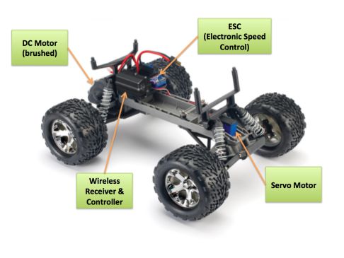

The ESC (Electronic Speed Control) unit is an electronic module, which receives PWM signals from the controller and varies speed and direction of the DC motor and also acts as dynamic brakes. ESCs are often used in RC models. The ESC has the capability to provide dynamic braking depending on the mode in which it is being operated.
CAN Design
CAN Communication Table
| Sr. No | Message ID | Message function | Message Data | From | To |
|---|---|---|---|---|---|
| High | |||||
| 1 | 0x220 | Motor Control (Direction Control- Straight, Left or Right Level of Direction-Level 0, Level1, Level 2 Motion Control- Stop, Forward or Reverse Speed Control - Stop, Level1, Level2 or Level3) |
Byte[0] -> Direction Control Byte[1] -> Level of Direction Byte[2] -> Motion Control Byte[3] -> Speed Control |
Master | Motor |
| 2 | 0x010 | Kill Message (User request to stop the car under emergency) |
Control Frame. No data bytes. | Android | Master |
| 3 | 0x020 | Kill Message (Master request to stop all controllers and reboot under emergency) |
Control Frame. No data bytes. | Master | All |
| 4 | 0x030 | Stop (User request to stop the car) |
Control Frame. No data bytes. | Android | Master |
| 5 | 0x040 | Stop (Master stops the motor) |
Control Frame. No data bytes. | Master | Motor |
| 6 | 0x210 | Sensor Data (Distance in cms) |
Byte[0] -> Forward Distance Byte[1] -> Left Distance Byte[2] -> Right Distance Byte[3] -> Back Distance |
Sensor | Master/Motor-IO |
| 7 | 0x230 | Total Distance to Travel | Byte[0-1] | Android | Geo |
| 8 | 0x240 | Send Checkpoints | Byte[0-3] -> Latitude Byte[4-7] -> Longitude |
Android | Geo |
| 9 | 0x250 | Distance (Distance in foot) |
Byte[0-1] -> Final Distance remaining Byte[2-3] -> Checkpoint distance Byte[4] -> Is_Last_Checkpoint |
Geo | Master |
| 10 | 0x260 | Turn Angle and Direction | Byte[0] -> Turn Angle Byte[1] -> Direction (1-Left,2-Right) |
Geo | Master |
| 11 | 0x270 | Run and Pause Command | Control Frame. No data bytes | Android | Master |
| 12 | 0x280 | Heartbeat Message | Control Frame. No data bytes | Motor | Master |
| 13 | 0x281 | Heartbeat Message | Control Frame. No data bytes | Geo | Master |
| 14 | 0x282 | Heartbeat Message | Control Frame. No data bytes | Android | Master |
| 15 | 0x283 | Heartbeat Message | Control Frame. No data bytes | Sensor | Master |
| Medium | |||||
| 16 | 0x410 | Destination reached. (Stops the car when destination is reached) |
Control Frame. No data bytes | Master | All |
| 17 | 0x420 | Battery Status | Byte[0-1] | Sensor | Master/IO |
| Low | |||||
| 18 | 0x610 | Boot Request | Control Frame. No data bytes | Master | All |
| 19 | 0x620 | Boot Reply (Date and time will be sent to Master) |
Byte[0-4] | Motor-IO | Master |
| 20 | 0x621 | Boot Reply (Date and time will be sent to Master) |
Byte[0-4] | Sensor | Master |
| 21 | 0x622 | Boot Reply (Date and time will be sent to Master) |
Byte[0-4] | Geo | Master |
| 22 | 0x623 | Boot Reply (Date and time will be sent to Master) |
Byte[0-4] | Android | Master |
| 23 | 0x630 | Boot Status (Enable the map and run button in Android) |
Control Frame. No data bytes | Master | Motor-IO/Android |
| 24 | 0x640 | System Start | Control Frame. No data bytes | Android | All |
| 25 | 0x650 | Source Co-ordinates | Byte[0-3] -> Source Latitude Byte[4-7] -> Source Longitude |
Geo | Android |
CAN Message Flow

DBC Implementation
Background
Generally, data received from the CAN message is handled using structures. If there are 'n' CAN messages, 'n' structures will be used to handle them. Data has to be encoded at one end for CAN transmission and decoded at the other end, after CAN reception. If there are innumerable CAN messages and their respective structures, lot of effort will be spent in writing code for encoding and decoding. A better approach is to use DBC. It has a specific format and generates automatic code consisting of decoding and encoding logic and structures for CAN messages.
DBC File
The following DBC file gives the proper description of CAN messages used in our car.
   VERSION ""


   NS_ :
        NS_DESC_
        CM_
        BA_DEF_
        BA_
        VAL_
        CAT_DEF_
        CAT_
        FILTER
        BA_DEF_DEF_
        EV_DATA_
        ENVVAR_DATA_
        SGTYPE_
        SGTYPE_VAL_
        BA_DEF_SGTYPE_
        BA_SGTYPE_
        SIG_TYPE_REF_
        VAL_TABLE_
        SIG_GROUP_
        SIG_VALTYPE_
        SIGTYPE_VALTYPE_
        BO_TX_BU_
        BA_DEF_REL_
        BA_REL_
        BA_DEF_DEF_REL_
        BU_SG_REL_
        BU_EV_REL_
        BU_BO_REL_
        SG_MUL_VAL_


BS_:
BU_: NOONE SENSOR MASTER MOTORIO ANDROID GEO

BO_ 220 MOTORIO_CMD: 4 MASTER
 SG_ MOTORIO_CMD_LeftRightdirection : 0|8@1+ (1,0) [0|2] "" MOTORIO
 SG_ MOTORIO_CMD_LevelOfDirection : 8|8@1+ (1,0) [0|5] "" MOTORIO
 SG_ MOTORIO_CMD_FrontBackDirection : 16|8@1+ (1,0) [0|2] "" MOTORIO
 SG_ MOTORIO_CMD_LevelOfSpeed : 24|8@1+ (1,0) [0|5] "" MOTORIO

BO_ 010 KILL_REQUEST: 0 ANDROID
 SG_ KILL_REQUEST : 0|0@1+ (1,0) [0|0] "" MASTER

BO_ 020 KILL_MESSAGE: 0 MASTER
 SG_ KILL_REQUEST : 0|0@1+ (1,0) [0|0] "" MOTORIO,SENSOR,GEO,ANDROID

BO_ 030 STOP_REQUEST: 0 ANDROID
 SG_ STOP_REQUEST : 0|0@1+ (1,0) [0|0] "" MASTER

BO_ 040 STOP_COMMAND: 0 MASTER
 SG_ ANDROID_HEARTBEAT_cmd : 0|0@1+ (1,0) [0|0] "" MOTOR

BO_ 210 SONARS: 4 SENSOR
 SG_ SENSOR_SONARS_FrontDistance : 0|8@1+ (1,0) [0|0] "" MASTER,MOTORIO
 SG_ SENSOR_SONARS_LeftDistance : 8|8@1+ (1,0) [0|0] "" MASTER,MOTORIO
 SG_ SENSOR_SONARS_RightDistance : 16|8@1+ (1,0) [0|0] "" MASTER,MOTORIO
 SG_ SENSOR_SONARS_RearDistance : 24|12@1+ (1,0) [0|0] "" MASTER,MOTORIO

BO_ 230 TOTAL_DISTANCE_TO_TRAVEL: 4 ANDROID
 SG_ TOTAL_DISTANCE_TO_TRAVEL: 0|16@1+ (1,0) [0|0] "" GEO

BO_ 240 SEND_CHECKPOINTS: 8 ANDROID
 SG_ SEND_CHECKPOINTS_Latitude: 0|32@1+ (1,0) [0|0] "" GEO
 SG_ SEND_CHECKPOINTS_Longitude: 32|64@1+ (1,0) [0|0] "" GEO

BO_ 250 DISTANCE: 4 GEO
 SG_ DISTANCE_FinalDistance : 0|16@1+ (1,0) [0|0] "" MASTER
 SG_ DISTANCE_CheckpointDistance : 16|16@1+ (1,0) [0|0] "" MASTER

BO_ 260 TURN_ANGLE_DIRECTION: 2 GEO
 SG_ TURN_ANGLE_DIRECTION_TurnAngle : 0|8@1+ (1,0) [0|0] "" MASTER
 SG_ TURN_ANGLE_DIRECTION_TurnDirection : 8|8@1+ (1,0) [0|0] "" MASTER

BO_ 270 RUN_PAUSE: 0 ANDROID
 SG_ RUN_PAUSE : 0|0@1+ (1,0) [0|0] "" MASTER

BO_ 280 HEARTBEAT_: 0 MOTORIO
 SG_ MOTORIO_HEARTBEAT_cmd : 0|0@1+ (1,0) [0|0] "" MASTER

BO_ 281 HEARTBEAT: 0 GEO
 SG_ GEO_HEARTBEAT_cmd : 0|0@1+ (1,0) [0|0] "" MASTER

BO_ 282 HEARTBEAT: 0 ANDROID
 SG_ ANDROID_HEARTBEAT_cmd : 0|0@1+ (1,0) [0|0] "" MASTER

BO_ 283 HEARTBEAT: 0 SENSOR
 SG_ SENSOR_HEARTBEAT_cmd : 0|0@1+ (1,0) [0|0] "" MASTER

BO_ 410 DESTINATION_REACHED: 0 MASTER
 SG_ SENSOR_HEARTBEAT_cmd : 0|0@1+ (1,0) [0|0] "" MASTER

BO_ 420 BATTERY_STATUS: 1 SENSOR
 SG_ BATTERY_STATUS_VALUE : 0|0@1+ (1,0) [0|0] "" MASTER,MOTORIO

BO_ 610 BOOT_REQUEST: 0 MASTER
 SG_ BATTERY_STATUS_VALUE : 0|0@1+ (1,0) [0|0] "" MOTORIO,SENSOR,ANDROID,GEO

BO_ 620 BOOT_REPLY_MOTORIO: 0 MOTORIO
 SG_ BOOT_REPLY_MOTORIO : 0|0@1+ (1,0) [0|0] "" MASTER

BO_ 621 BOOT_REPLY_SENSOR: 0 SENSOR
 SG_ BOOT_REPLY_SENSOR : 0|0@1+ (1,0) [0|0] "" MASTER

BO_ 622 BOOT_REPLY_GEO: 0 GEO
 SG_ BOOT_REPLY_GEO : 0|0@1+ (1,0) [0|0] "" MASTER

BO_ 623 BOOT_REPLY_ANDROID: 0 ANDROID
 SG_ BOOT_REPLY_ANDROID : 0|0@1+ (1,0) [0|0] "" MASTER

BO_ 630 BOOT_STATUS: 0 MASTER
 SG_ BOOT_STATUS : 0|0@1+ (1,0) [0|0] "" MOTORIO,ANDROID

BO_ 650 SOURCE_COORDINATE: 8 GEO
 SG_ SOURCE_COORDINATE_LATITUDE : 0|32@1+ (1,0) [0|0] "" ANDROID
 SG_ SOURCE_COORDINATE_LONGITUDE : 32|32@1+ (1,0) [0|0] "" ANDROID

CM_ BU_ NOONE "No node, used to indicate if it's a debug message going to no one.";
CM_ BU_ MASTER "The Master controller driving the car.";
CM_ BU_ SENSOR "The Sensor controller of the car.";
CM_ BU_ MOTORIO "The Motor-IO controller of the car.";
CM_ BU_ ANDROID "The Android controller of the car.";
CM_ BU_ GEO "The Geo controller of the car.";
CM_ BO_ 100 "Sync message used to synchronize the controllers";

BA_DEF_  "BusType" STRING ;
BA_DEF_ SG_ "FieldType" STRING ;
BA_DEF_ BO_ "GenMsgCycleTime" INT 0 0;

BA_DEF_DEF_ "BusType" "CAN";
BA_DEF_DEF_ "FieldType" "";

BA_ "GenMsgCycleTime" BO_ 220 10;
BA_ "GenMsgCycleTime" BO_ 210 10;
BA_ "GenMsgCycleTime" BO_ 250 10;
BA_ "GenMsgCycleTime" BO_ 260 10;
BA_ "GenMsgCycleTime" BO_ 280 1;
BA_ "GenMsgCycleTime" BO_ 281 1;
BA_ "GenMsgCycleTime" BO_ 282 1;
BA_ "GenMsgCycleTime" BO_ 283 1;
BA_ "GenMsgCycleTime" BO_ 420 1;

VAL_ 100 MASTER_HEARTBEAT_cmd 0 "MASTER_HEARTBEAT_cmd_NOOP" 1 "MASTER_HEARTBEAT_cmd_SYNC" 2 "MASTER_HEARTBEAT_cmd_REBOOT";
Detailed Description
1)The above description shows the detailed implementation of the CAN messages used for communication between various controllers. Several types of notations are used in this DBC file. Following is the explanation of these notations which includes range of the CAN data, minimum, maximum values, and number of data bits used in the 64 bit structure. One useful feature of CAN message frame is bitwise access of data. This approach of accessing data using bits instead of bytes avoids wastage of CAN data which could otherwise be utilized properly.
2)Detailed explanation of notations used in CAN dbc file format-
 a. BU_: NOONE SENSOR MASTER MOTORIO ANDROID GEO
  The line which is starting with BU_ gives us the information about all the controllers present in the communication BUS.

 b. BO_ 220 MOTORIO_CMD: 4 MASTER
  i.This is the message command which states the message ID. Here 220 is the message ID used for Motor command from Master to Motor.
  ii.The name of the message is MOTORIO_CMD which forms a string of the structure to be created in the auto generated code.
  iii. 4 represents size of data in byte to be transmitted.
  iv.Here last text is written as MASTER, which says that the message is originating from MASTER.

 c. SG_ MOTORIO_CMD_LeftRightdirection : 0|8@1+ (1,0) [0|2] "" MOTORIO
  i.The line has SG_ in the beginning and is known as the signal. This command tells us about the number of different data
  in the CAN message.
  ii.0|8 -> 0 is the start bit of the data in the CAN message and 8 is the length of the data in the CAN message.
  iii.[0|2] -> 0 is the minimum value of the data and 2 is the maximum value of the message.
  iv.The last text MOTORIO defines the number of receivers of the message. There can be more than one receivers.
  If there are,then they are separated by a comma.
  v.Here ‘MOTORIO_CMD_LeftRightdirection’ is the name of the data that is being transmitted in the message.

 d. BA_ "GenMsgCycleTime" BO_ 220 10
  i.This command describes the general message cycle.
  ii.Here the message 220 i.e the motor command repeats itself after every 10 Hz i.e 100 ms.
  iii.Similarly, there are some message which repeats after every 1 Hz.
3)The dbc file was created with these normal basic command and was sent as an input to the python dbc parser which decrypted it to the auto generated code. Following is the python command for the dbc parser:
>python.exe dbc_parse.py -i Group2.dbc -s MASTER -a -b >generated.h
Design & Implementation of Controllers
Motor and I/O Controller
Schedule
| Sl. No | Start Date | End Date | Task | Status | Actual Completion Date |
|---|---|---|---|---|---|
| 1 | 9/21/2015 | 9/25/2015 | Order LCD Display | Completed | 9/25/2015 |
| 2 | 9/28/2015 | 10/3/2015 | Going through the motor concepts and PWM | Completed | 10/2/2015 |
| 3 | 10/4/2015 | 10/9/2015 | Intreface the DC and SERVO Motors with SJONE board | Completed | 10/8/2015 |
| 4 | 10/10/2015 | 10/13/2015 | Establishing basic CAN communication with other modules | Completed | 10/13/2015 |
| 5 | 10/11/2015 | 10/16/2015 | Getting the car to run with the PWM signals from Motor controller | Completed | 10/15/2015 |
| 6 | 10/17/2015 | 10/23/2015 | Research on Speed cotrol method and sensor for the same interface LCD display with LPC1758 via UART | Completed | 10/21/2015 |
| 7 | 10/23/2015 | 11/4/2015 | Establishing reliable CAN communication for IO & Motor with others | Completed | 11/4/2015 |
| 8 | 11/5/2015 | 11/12/2015 | Integrate Speed sensor and get feedback. Start working on start,stop buttons and headlight | Completed | 11/11/2015 |
| 9 | 11/13/2015 | 11/30/2015 | Testing substantial self driving capability of the car | Completed | 12/5/2015 |
| 10 | 11/21/2015 | 11/30/2015 | Complete integration, Debugging and Fine tuning | Completed | 12/5/2015 |
| 11 | 12/1/2015 | 12/5/2015 | Final Validation | Completed | 12/15/2015 |
Hardware Design
Motor Module
The motor module comprises of a servo motor for the direction control and a DC motor for speed control. The servo motor helps the car in turning left and right where as the DC motor on the other hand helps the car move forward and backward. The DC motor used in the project is a brushed motor. Conventionally, brushless motors are faster and more efficient than brushed motors. But, the reason for selecting a brushed motor over a brushless motor is that we employ a dedicated battery for the motor such that we do not have any issues with power and efficiency. Moreover, we need not operate the car at high speeds.
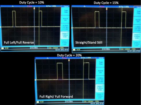
The initial task in the motor module is to find the operating ranges of the motor so that we get to know the output signal range and frequency from the SJONE board which would be replacing the pre-programmed controller. The simplest way to find the operating ranges of the motor is to tap and analyze PWM signal that is being supplied to the motor over an oscilloscope. The results as shown in the below pictures indicate that the operating duty cycle of both the motors lie between 10% to 20% and the frequencies at which the motors operate is 100Hz.

The hardware interface of the Motors and SJONE board includes the following connections.
| Sl. No | Connection on the car | Pin on SJSU One Board | Purpose |
|---|---|---|---|
| 1 | Input to DC Motor | P2.1 | PWM input to drive DC motor |
| 2 | Input to Servo Motor | P2.0 | PWM input to drive DC motor |
| 3 | Speed sensor | P2.4 | PWM output from speed sensor |
The Motor controller receives the commands from the Master controller which guides it to navigate the car based on the information from the Sensors and GPS. While it does so, it also needs to get feedback from the DC motor and control the motor independently in order to ensure that the car is moving with the speed requested by the Master. This requires increasing or decreasing the actual speed level that is being provided to the Motor in case of movement along uphill, downhill, grass and high friction tracks.
The feedback is achieved through a shaft encoder which works based on Hall-effect. The installation of the speed sensor was pretty easy as we went with the one from Traxass, the same manufacturer as our RC car. It involves removing the DC motor casing, placing the sensor over the spur gear and the magnet holder. The sensor would sense the rotation of the axle. It produces a pulse when the magnet comes into the line of the sensor, which is then detected by the Motor controller.
IO Module
The IO module Consists of a 4 line * 20 characters serial LCD. Data from GPS and sensor module is displayed continuously by refreshing it every second. SJ one board communicates with LCD through UART.
GPS data :-
- Distance travelled
- Checkpoint Distance
Sensor data:-
- Left sensor reading
- Right sensor reading
- Front sensor reading
- Rear sensor reading
Additionally, IO module controls lighting up headlights/taillights based on the direction of the car movement.

LCD unit requires 5V power supply for its working. The VCC and Ground pins are connected to common power supply lines that is used to power up all the boards. The Rx pin of LCD is connected to TXD2 (p2.8) pin on SJ one board. Two of the GPIO pins p2.6 and p2.7 controls the headlights LED’S and taillights LED’S respectively.
| Sl. No | Pin on IO Module | Pin on SJSU One Board | Purpose |
|---|---|---|---|
| 1 | Vcc | Common power supply | 5V for LCD |
| 2 | Ground | Common Ground | Ground for LCD |
| 3 | Rx | P2.8(TXD2) | Receive data from SJone board through UART |
| 4 | Headlight LED’s(2) | P2.6 | Turn on headlights when car is moving in the forward direction |
| 5 | Taillight LED’s (2) | P2.7 | Turn on tail-lights when car is moving in the reverse direction |
Usage of OnBoard LED's:
| LED No. | Usage |
|---|---|
| 1 | Speed feedback control active |
| 2 | Master commands to Motor |
| 3 | Heart beat |
| 4 | Can reception failure |
Software Design
Module Flow

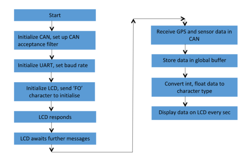
The controller on boot up initializes the CAN communication, UART and also the PWM for initialization pulse required for the motor to run.The inter-controller communication is done over CAN bus. It is configured to receive and transmit messages at 100K baud-rate. The type of CAN ID is Standard. Later these are accomplished at run time using the periodic scheduler task.
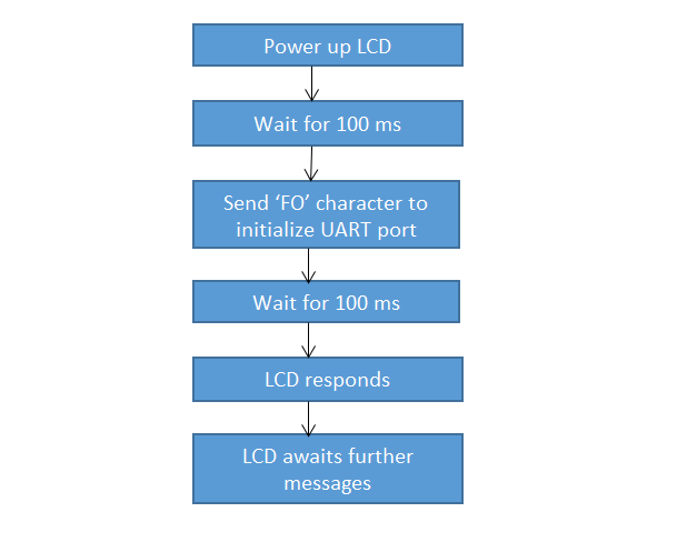
LCD communicates with SJ one board through UART. Communication will happen between LCD and SJone board only when the baud rates are synchronized. The UART port is configured to operate at 19200 bps. “FO” character is sent to initialize the UART port after a delay of 100 ms, upon powering up the board. The display unit responds after 100 ms. Now the LCD module is configured and can receive further messages to display on it. Data from modules such as GPS and sensor are received continuously through CAN. It is decoded, converted into proper format and displayed on the LCD periodically. The corresponding flow is shown below.

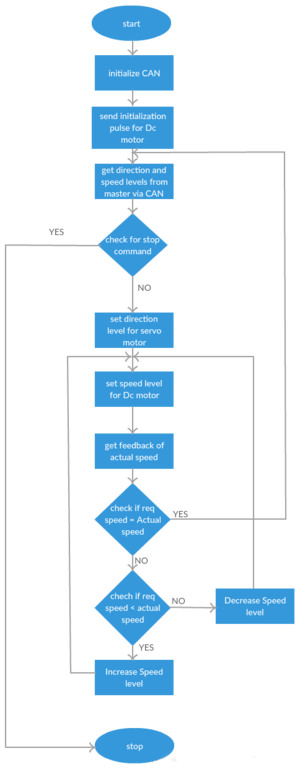
The Motor controller, after sending the initialization pulse to the DC motor, waits for a start command from the Master over CAN and then controls the motors in order to reach the destination with required levels of speed and direction. The control algorithm for the Motor operation is as shown on the right.
Software Implementation
“Can receive” function is called in periodic scheduler 100 Hz task. This function lets the Motor/IO module receive CAN messages from other modules connected to it. CAN set up filter function has been used to accept only essential messages required by this module. Based on the CAN message identifier, corresponding action is performed. These are the CAN messages required by the motor/IO module.
CAN MESSAGE ID:-
- 0x020 – Kill message
- 0x210 – Sensor data
- 0x220 - Motor control message
- 0x250 – GPS data
- 0x610 – Boot request
Data from sensor and GPS modules are stored in global message buffers. Sensor data is 8 bit whereas GPS data ranges between 16-32 bits. These integer values are converted into character type and then sent to LCD through UART. LCD display function is called in 1Hz periodic scheduler task. Thus Sensor and GPS data get displayed on the LCD every sec.

The 3D design used as a support for mounting the LCD is shown below:

Motor Control
On receiving the CAN message(0x220) from the Master, the data is extracted and and used for specific functions as shown below.
          *Byte0 --> Servo Direction
          *Byte1 --> Servo Level
          *Byte2 --> DC Direction
          *Byte3 --> DC Level
Based on this data, the first two bytes decide the direction(left/right) and the level(angle), respectively in which the car should turn using the Servo motor. Similaly, the next two bytes decide the direction(forward/backward) and the level(speed) in which the car has to move.
To implement all the motor related functions, we have employed a dedicated task. Initially, the pre-scaled PWM values are fed to the motors based on the direction and level from the Master. We have a bit robust algorithm to obtain these PWM values which has offsets and level multipliers. The advantage of this is we can change the code to function for multiple levels with minimum effort.
A piece of code for Motor Control:
switch(DC_control)
       {
           case 0:
           	if(DC_level==DC_level_last)
           	{
                   	speed_offset = 0;
                   	speed_factor =0;
                   	LD.setNumber(10);
           	}
           	else
           	{
           		pwm2.set(15);
           		vTaskDelay(25);
           		pwm2.set(13);
                   	vTaskDelay(100);
                   	speed_offset = 0;
                   	LD.setNumber(13);
                   	speed_factor =0;
           	}
           	p2_pin6.setLow();
           	p2_pin7.setLow();
          		speed_offset = 0;
           	speed_factor =0;
           	count_rev = 1;
           	break;
           case 1:
           	speed_offset = 0.4;
           	speed_factor = 0.2;
           	count_rev = 1;
           	p2_pin6.setHigh();
           	p2_pin7.setLow();
           	break;
           case 2:
           	speed_offset = -0.6;
           	speed_factor = -0.2;
           	p2_pin6.setLow();
           	p2_pin7.setHigh();
           	break;
           default:
           	speed_offset = 0;
           	speed_factor =0;
           	count_rev = 1;
           	p2_pin6.setLow();
           	p2_pin7.setLow();
           	break;
       }
       PWM_value_DC = 15 + (speed_factor)*(DC_level) + speed_offset;
Motor Feedback
After feeding the motors with the required levels, we have to check if the car is actually moving at that speed. This is ensured through feedback and control based on that. The feedback is obtained through the speed sensor collaborated with the DC motor, which triggers a pulse on every rotation and this is recorded by a rising edge based interrupt. The interrupt callback function increments the number of pulses. A separate logic is used to calculate and then compare the actual and required(from Master) speed levels. The corrective measures are enforced to achieve the desired speed.
The transmit messages, except Heart beat message(sent every one second), are transmitted once every 100ms. The Motor/IO controller, on receiving a boot request from Master controller, transmits a boot reply message in order to let the Master know that it has booted successfully. The heart beat message is transmitted continuously to indicate that the controller is active and this will be acknowledged by the Master.
Testing
Motor Control
The motor operation is initially tested for its accuracy with different direction and levels such as forward, reverse, left, right. After ensuring everything is as expected, we went for refining it. Later, with the speed sensor installed, the functioning of it and the control based on it has to be checked properly. For this, we have tested the car by running it over ramp-up, ramp-down, grassy and rough paths. Then we have refined it. Finally, we made sure that the car gets back to the required speed when it deviates from the same.
Technical Challenges and Resolution
Motor Feedback
The major difficulty with motor speed feedback was getting enough number of pulses from the speed sensor in order to calculate the current speed. When we run at very low speeds, we get pulses as low as 2 0r 3 at even 10Hz. If the same value is multiplied by required factor(say 600 in 10Hz) to get the rpm, then we have a couple of issues.
i) Firstly, we cannot get intermediate speed values as we get only in multiples of the the factor which will be very high.
ii) Secondly, we may have some issues, at very low speeds, like we don't get a pulse every 100ms or 10ms, which means the motor is at rest but which actually is not.
Solution: Never try to implement in terms of "rpm". Instead go for "rps" or "m/s". This will eliminate the first issue. And to solve the second problem, we may think of aggregating the pulse count for a greater time interval. But this will lead to a delayed feedback which in turn leads to an undesired behavior. Hence we have a trade-off between the two.
Motor Control
1) The first hurdle one would face with the Motor control through an ESC is starting the motor. This requires an initialization pulse, which would have been sent by the transmitter earlier. We have to realize the required pattern or PWM value for the achieving this.
2) The second difficulty with the motor comes into picture when with backward movement of the car. Due to the presence of the ESC and the residual momentum in forward direction, we cannot alter the direction of the motor suddenly. We have to manually discover the pattern required for this forward to reverse transition which takes a bit of time unless one is aware of it.
Master Controller
As the name suggests, it is main controller on the car which interacts with all other controllers over the CAN Bus to achieve real-time functionality. Basic function of the Master Controller is to receive data from Android, Geo and Sensor Modules and develop the algorithm to drive the car autonomously based on the received data through the Motor Controller.
Schedule
| Sl. No | Start Date | End Date | Task | Status | Actual Completion Date |
|---|---|---|---|---|---|
| 1 | 09/30/2015 | 10/6/2015 | a) Design of Algorithm and Architecture for Master Module. b) Setup of CAN communication between two controllers. |
Completed | 10/6/2015 |
| 2 | 10/7/2015 | 10/13/2015 | a) Development of CAN message system for Android, Sensor and GPS, I/O reception. b) Decide about periodic function frequencies that’ll be handling different modules. |
Completed | 10/13/2015 |
| 3 | 10/14/2015 | 10/20/2015 | a) Development of driving,stopping and obstruction avoidance algorithm for motor. b) Implementation of LED Display to display number of messages on CAN bus. c) Implementation of turning algorithm as per the data received from the Geo Controller. |
Completed | 10/20/2015 |
| 4 | 10/21/2015 | 10/27/2015 | a) Designing of Kill switch with the help of Motor, I/O and Android. b) Design the system to restore the last known configuration. c) Implementation to reset modules if the CAN bus reaches BUS off state. |
Completed | 10/27/2015 |
| 5 | 10/28/2015 | 11/3/2015 | a) Design of Head Light functionality with the help of Sensor module. b) Implementation of log files saving to SD card. |
Completed | 11/1/2015 |
| 6 | 11/4/2015 | 11/10/2015 | a) Integration of all the modules with Master module and check it after combining everything. b) Probable implementation of additional features. |
Completed | 12/05/2014 |
| 7 | 11/11/2015 | 11/17/2015 | a) Refine the work done earlier.Change areas that need a change. b) Test the Master module while all the modules are integrated together and list down modifications and additions to be done. |
Completed | 12/05/2014 |
| 8 | 11/18/2015 | 11/24/2015 | Testing of system and specially making sure that last week’s shortcomings are taken care of. | Completed | 12/05/2014 |
| 9 | 11/25/2015 | 12/1/2015 | a) Final testing of individual modules. b) Testing the self-driving capability of the car. |
Completed | 12/05/2014 |
| 10 | 12/2/2015 | 12/8/2015 | Final working on the shortcomings in the previous week. | Completed | 12/8/2015 |
| 11 | 12/9/2015 | 12/15/2015 | Final Testing of Car. | Completed | 12/15/2015 |
Hardware Design
- RC car was the basic infrastructure that was required to implement the project.
- CAN Bus with five SJone controller boards was integrated on General purpose Printed Circuit Board (PCB).
- Sufficient power-supply ports and external pins were provided to each controllers.
- Flat Ribbon Cables were used to reduce circuit complexity arising from external connecting wires.
Usage of OnBoard LED's:
| LED No. | Usage |
|---|---|
| 1 | Forward signal to Motor |
| 2 | Left turn signal to Motor |
| 3 | Right turn signal to Motor |
| 4 | Reverse signal to Motor |
Software Design
This section describes about the general algorithm used for master programming. There are a lot of cases in Master Controller which are to be handled in order to run the car properly. This includes heartbeats, boot messages, running of motor, reading of the sensor values properly and then taking proper decision. The other activities that are done in master are listed below with some fair explanations.
- Master Controller uses FreeRTOS environment to achieve its functionality.
- It uses Periodic Scheduler Task provided by Preet at its core to communicate with all other controllers.
- The functions of the Periodic Scheduler Task were used in a customized manner to transmit/receive the messages at specific intervals of 1Hz,10Hz,100Hz and 1000Hz.
- File logger function was used to log the real-time data onto SD card which was used for debugging purpose.
- Can Message structure of 11-bit id was implemented to send and receive CAN messages over the CAN Bus.
- CAN acceptance filter was set-up to receive messages specific to Master Controller from the CAN Bus, since it is the broadcast Bus.
Software Implementation
- Master Controller starts with initialization of CAN Bus and setting up reception filter from the main() function.
- The Periodic Scheduler Task then takes over to implement the actual functionality of the Master Controller.
- CAN_is_busoff() was used at an interval of 10Hz through periodic scheduler task to check if the controller was always connected to CAN bus.
- Following are the algorithms that were implemented in the Master controller to drive the motor.
Algorithm
Geo Processing Algorithm
Following is the algorithm that was implemented to process the data sent by Geo controller, which eventually navigates the car towards its destination. At first, it checks if there is any obstruction in the car’s path, if there is no obstruction it follows the further steps, And if there is an obstruction, it transfers control to the Obstruction Avoidance Algorithm.
Step 1: Check if there is no obstruction. If there is no obstruction proceed to step2, otherwise proceed to step7.
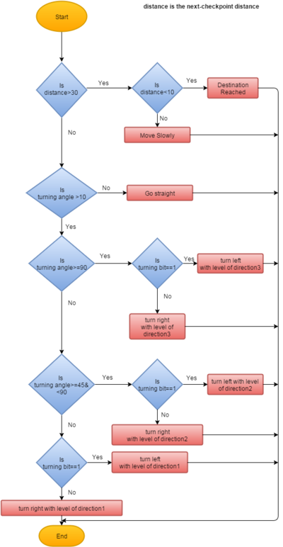
Step 2: Check if distance towards next check-point is greater than 30. If distance towards next check-point is greater than 30, proceed to step3, otherwise go to Step 6.
Step 3: Check if turning angle is greater than 10. If turning angle is greater than 10, proceed to step4, otherwise go straight go to step7.
Step 4: Check if turning angle is greater than or equal to 90. If turning angle is greater than or equal to 90, turn left or right according to the turning bit with level of direction 3 go to step7,otherwise proceed to step5.
Step 5: Check if turning angle is greater than or equal to 45 and less than 90. If turning angle is greater than or equal to 45 and less than 90, turn left or right according to the turning bit with level of direction 2, otherwise turn left or right according to the turning bit with level of direction 1 go to step7.
Step 6: Check if distance towards next check-point is less than 10.If the distance is less than 10, stop the car, otherwise move slowly with level of speed 1.
Step 7: End.
Following is the flow-chart of the above algorithm:

Obstacle Avoidance Algorithm
The most important part of the Master controller is to control the motors and handling other decision making factors such as when to move and when to not. The Motor/IO controller is almost entirely dependent on the Master controller to drive the motor. The Master controller is responsible for making decisions on when and where to move the car in case of any obstacle and this is where the Sensor controller comes into the bigger picture.
1)For exact precision, we are considering most accurate algorithm for Sensor Processing. We have defined three levels of obstacle zones. The exact explanation of this terminology can be understood from the gif image shown below.

2) There are three zones in which the major sensor processing for obstacle-avoidance is done. In these zones, distances were designated as the safest distance for the car in which it can move ahead though at low speeds. In addition, we also had taken the danger zone into the consideration.Within danger zone distance, the car won’t be able to move ahead and would only take reverse depending on data from rear sensor. Following is the classification of the various zones:
Front:
FDanger : This distance would be the distance within 40 cms of the car. Within this distance, the car wouldn’t be able to move ahead and would only take reverse turn only if there is no blockage from the rear side.
F1 :
F1 is the zone between 40 cms and 80 cms. Within this zone, the car speed would be very slow. Since this distance is very short, we have assured that the speed of car is very slow with the motor feedback and then it will take some necessary decisions.
The turn angles in this case would be in the higher range since there would be a necessity to take sharp turns to avoid obstacles.
F2 :
The range of 80 to 130 cms defines the zone F2. The car would run at more higher speeds in this zone.
The turn angles in this case would be in a lesser range as compared to F2 zone.
F3 :
The range of 130 cms to 190 cms defines the zone F3. The car won’t make any turning decisions in this range but would only reduce its speed. We have made sure that within this range of obstacle detection, the speed of the car won’t be so much that could cause problem in obstacle avoidance in the inner zones.
Left & Right:
LDanger and RtDanger :
LDanger and RtDanger is the zones for the left and the right sensor obstacle, the distance values are within 40 cms of the car.
L1 and Rt1 :
For L1 and Rt1, the distance between 40 cms and 70 cms is considered. This distance is somewhat more than the danger distance and the car could only have speed level 1 in this condition and the turning angles are rather sharp.
L2 and Rt2 :
L2 and Rt2 is considered as the zone between the distance 70 cms and 120 cms. In this zone, level of speed is little higher and the turning angle levels are little lesser than previous zone.
L3 and Rt3 :
The range of 120 cms to 150 cms is considered as the zone L3 and Rt3. In this zone, only the speed of the car is reduced.
Rear :
Reverse :
We have only a single zone for the reverse-motion using rear sensor.
The reason for this is that there won’t be a significant movement in the reverse direction. So, there is not much use of handling the reverse conditions at a higher priority. Just a single level and every case can be handled properly.
The range of the obstacles finding for the reverse sensor is 60 cms.
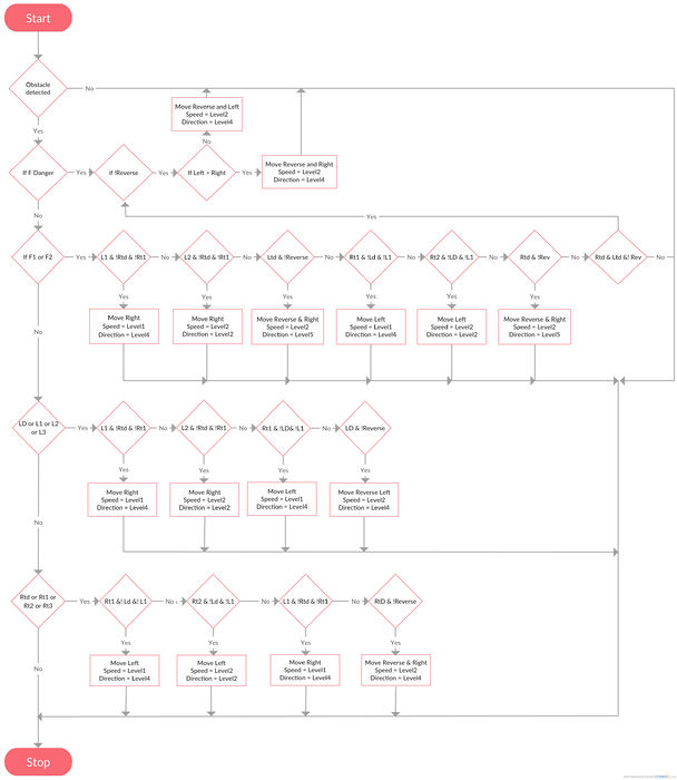
We have considered all the cases for each of the zones, but during the actual running of the car, there were some cases which were only used 0.5% of the times. Just to improve the response of the algorithm, we have ignored those cases and concentrated on all the other cases. The results were fascinating since the reverse algorithm was responding very sharply. These were all the theoretical explanation about the levels. The, actual algorithm is shown using a flow diagram below. This would clearly showcase how the car would run and in what conditions.

Technical Challenges and Resolution
Sensor algorithm
Just a straightforward algorithm is easy and short to implement. But the sensor are tested properly when there are a lot of corner cases of obstacles where the car can stuck. These corner cases were indeed a challenge that was faced. These cases were developed in step and the entire algorithm was not implemented at once.
CAN Message Handling
Collaborating on the message id’s and the data in those messages. Since master is the powerhouse of the system, there are a multiple number of nodes communicating with Master. Since such a number of nodes are communicating with Master, there are a lot of cases which are to be handled in Master and that was indeed a challenging task.
Integrating Sensor and Geo Algorithms
There were a lot of problems faced while integrating Geo controller and Sensor controller. The first and foremost problem that we faced was while implementing any new feature and synchronising other controllers with the Master controller. For example, the sensors were integrated earlier but when the Geo controller was integrated, the motor did not receive proper data. On debugging, we came to know that the problem was with the algorithm and after we changed it, everything was working on its proper way.
CAN Arbitration
Since Master controller was the one with a lot number of messages, we faced some issues regarding CAN arbitration. Initially, there were a couple of messages which were high priority messages and were blocking the way of some important low priority one time messages. But after some changes in the ID’s the problem was dealt properly.
Sensor Controller
Schedule
| Sl. No | Start Date | End Date | Task | Status | Actual Completion Date |
|---|---|---|---|---|---|
| 1 | 9/20/2015 | 10/5/2015 | Study available sensors and place order | Completed | 10/4/2015 |
| 2 | 10/6/2015 | 10/13/2015 | Collaborate with the other sub teams to finish the CAN bus communication | Completed | 10/13/2015 |
| 3 | 10/13/2015 | 10/20/2015 | Develop simple test code for the sensors | Completed | 10/18/2015 |
| 4 | 10/21/2015 | 10/30/2015 | Interface all sensors and develop code for reading all sensors. | Completed | 10/30/2015 |
| 5 | 10/30/2015 | 11/2/2015 | Positioning of sensors and identifying dead band if any | Completed | 11/2/2015 |
| 6 | 11/06/2015 | 12/17/2015 | Final testing and debugging | Completed | 11/29/2015 |
Hardware Design
Sensor controller consists of sonar and ultrasonic sensors that are inter-connected to the SJOne board and CAN bus. The sensors detect if there is any obstacle around the car and report the distance of obstacle. Hardware design consists of four sensors connected to port 2 of LPC1758. The sensor in the front direction is MB1010 sonar sensor while the ones at back,right and left direction are HCSR04 ultrasonic sensors. The sensors are connected to +5V power supply to achieve the highest beam pattern that is available.
Sensor Hardware Interface

MB1010 LV MaxSonar EZ1 Sensor
The LV MaxSonar EZ detects objects from 0 inches to 254 inches and provides sonar range from 6 to 254 inches with 1 inch resolution. Objects from 0 to 6 inches are reported as 6 inches. Sensor operates at 42KHz. The sensor reports output formats in from of pulse width output, analog voltage output, and RS232 serial output. We have selected pulse width output.The sensor will continually measure range and output if RX data is left unconnected or held high. If held low the sensor will stop ranging. We have commanded a range reading by triggering high for 20uS.
Below are the timing diagrams for the sensor


HCSR-04 sensor
HCSR-04 sensor is a ultrasonic ranging module which detects obstacle from 0 to 400 cm. It is a four pin module – Vcc, trig, echo and Gnd. It includes transmitter, receiver and control circuit. The sensor operates at 40 KHz.It Requires 5V 15mA power supply. When a short 10uS pulse is provided to the trigger input, the sensor will transmit out 8 cycle of ultrasonic burst at 40kHz and makes the echo pin high.The Echo pin is lowered to logic low when the ultrasound burst is reflected off a distant object.To obtain the distance, measure the width (Ton) of Echo pin. Time = Width of Echo pulse, in uS (micro second) Distance in centimeters = Time / 58 Distance in inches = Time / 148 Or you can utilize the speed of sound, which is 340m/s


| Pin Name | Function |
|---|---|
| P2_0 | RX trigger for front Sensor |
| P2_1 | PWM for front Sensor |
| P2_2 | Trig for back Sensor |
| P2_3 | Echo for back Sensor |
| P2_4 | Trig for left Sensor |
| P2_5 | Echo for left Sensor |
| P2_6 | Trig for right Sensor |
| P2_7 | Echo for right Sensor |
3D Printing Design
The 3D design used as a support for mounting the sensors is shown below:

Usage of OnBoard LED's:
| LED No. | Usage |
|---|---|
| 1 | Boot Reply Successful |
| 2 | Heartbeat |
| 3 | Can reception successful |
| 4 | Can transmission successful |
Software Design

Software design for Sensor controller includes sensor initialization, sequential triggering of sensors, calculating distance of obstacle from the echo received and transmitting the data on CAN bus. Sensor initialization includes interrupt configuration for echo pins of sensor and configuring the trigger pins as output. A trigger of 20 us is required for MB1010 sensor and 10 us is required for HC SR-04 sensor.
Algorithm
- Initialize trigger pins as output to provide trigger pulse to sensors
- Initialize interrupt pins to receive echo or PW from sensors
- Trigger Front and back sensor
- Wait for echo or PWM pulse
- Capture start time frame on rising edge of interrupt and end time frame at falling edge of interrupt of the sensor
- Trigger Left and Right sensor
- Wait for echo or PWM pulse
- Capture start time frame on rising edge of interrupt and end time frame at falling edge of interrupt of the sensor
- Calculate distance on basis of the time captures in previous steps.
- Broadcast distance on CAN bus
This is a piece of our Interrupt configurations and function callbacks that calculate the distance of sensor.

Module Flow

Testing and Technical Challenges
Sensor Triggering
- Initially while testing sensors the triggering was in continuous mode without waiting for appropriate sensor processing time. This resulted in multiple errors in distance measured and eventually damaged the sensor. The readings were stable if the sesnors were triggered every 50ms for MB 1010 sensor and 30 ms for HC SR 04 sensor. Below are the testing results for triggering sensors at different time intervals


Referring to the above results we can conclude that the sensor data is more accurate for MB1010 if the time interval for triggering is 50ms. Similarly for HC SR04 the readings are accurate if time interval between the trigger is 30 ms.
Sensor Operating frequency
- Now if one waits for sequential triggering for all 4 sensors the wait time will be long, resulting in sensor data at low frequency. Hence to make sensors operate at 10Hz, the sensors are triggered in pairs( Front- Back and Right- Left). This has resulted in operating frequency of 10Hz concurrently avoiding interference between adjacent sensors.
Ground Reflections
- During testing, we observed that that the reflection from ground surface resulted into incorrect readings. This issue was resolved by tilting the 3D frames backward so that the ground reflections were minimal.
- When the car was tested for obstacle avoidance in the university corridors, at particular angles the sensor readings were maximum even though there was presence of wall in front of the sensor. This was overcome by slightly moving the positions of the sensors but could not be resolved completely.

Geographical Controller
Geographical Controller consists of GPS and Compass module. GPS module tracks current position (Latitude and Longitude) of the car and compass module gives the heading of car with respect to north. With the data provided from these modules, turn angle and distance to destination is calculated. Algorithm for these calculations is explained in software section.
Heading: Heading is the current direction of car, measured clockwise with respect to geographic north and ranges from 0 to 360 degrees. The compass gives the values with respect to magnetic north and the Magnetic declination is added to these values to give the actual heading.
Bearing: Bearing is direction of destination point with respect to north measured clockwise and ranges from 0 to 360 degrees. This value is calculated from destination and current coordinates using Haversine formula described in software section.
Turn Angle : It is a measurement in degrees that the car needs to take to head towards destination. It is calculated by using Heading and Bearing values.
Direction : It is the clockwise or anti clockwise turn of the car to head towards destination.
Schedule
| Sl. No | Start Date | End Date | Task | Status | Actual Completion Date |
|---|---|---|---|---|---|
| 1 | 09/27/2015 | 10/07/2015 | Ordering Parts and understanding each module | Completed | 10/11/2015 |
| 2 | 10/07/2015 | 10/13/2015 | CAN Communication with other boards and understanding each module | Completed | 10/13/2015 |
| 3 | 10/07/2015 | 10/30/2015 | Algorithm for distance and heading calculation and coding | Completed | 10/30/2015 |
| 4 | 10/14/2015 | 10/20/2015 | Interfacing of compass(I2C) and GPS (UART) with SJONE board | Completed | 10/20/2015 |
| 5 | 10/20/2015 | 10/30/2015 | Coding, Compass Calibration,GPS Calibration | Completed | 11/10/2015 |
| 5 | 10/25/2015 | 11/15/2015 | Individual unit testing | Completed | 11/20/2015 |
| 6 | 10/30/2015 | 11/30/2015 | Interfacing with Android, Master and IO controllers | Completed | 12/05/2015 |
| 7 | 10/30/2015 | 11/30/2015 | Integration Testing,On Car Calibration | Completed | 12/15/2015 |
Hardware Design
Schematic

SparkFun Venus GPS with SMA Connector
SparkFun Venus GPS uses Skytraq VENUS634FLPx IC. The Venus638FLPx outputs standard NMEA-0183 or SkyTraq Binary sentences at a default rate of 9600 bps which is adjustable to 115200 bps, with update rates up to 20Hz. We configured this module with update rate of 10Hz and 38400 bps UART rate. Module outputs GGA, GSA, GSV, GLL, RMC, VTG, ZDA NMEA standard messages which can be configures to as per our requirements. We configured it to give only GGA messages.
GGA message format is shown below.
For configuring GPS modules to UART rate 38400 bps, 10Hz update rate and only GGA message at output, below binary commands are used.


HMC5883L
HMC5883l is a triple axis digital compass IC used for heading calculation. It has magneto resistive sensors that forms the basis of the working principle of a compass. Please refer data sheet attached in reference section for specifications of the IC. Note that this IC is not tilt compensated and we need to calibrate for instrument error and for tilt.

HMC5883L and I2C
HMC5883L IC communicates to SJOne Board through I2C bus.
SJONE board -Master device
HMC5883L - Slave device
I2C rate is controlled by the master and can be upto maximum 400 KHz. We have configured the rate as 100 KHz.
Master Transmitter Mode -Slave Receiver Mode
In this mode, the master writes to the slave registers.
Compass IC has a set of 8 bit registers to be initially configured for parameters such as device output rate, number of samples, device gain and operating mode. By identifying the device write address and register address, the values can be written by the SJONE board to compass registers.
Master Receiver Mode -Slave Transmitter Mode
In this mode, the master reads from the slave registers.
X,Y,Z registers of the compass can be then read by SJOne board one by one knowing the device read address and register address.Register pointer will be incremented by 1 automatically after current register has been successfully read.
Usage of OnBoard LED's
| LED No. | Usage |
|---|---|
| 1 | I2C Device response successful |
| 2 | Compass read successful |
| 3 | Checkpoints reception successful |
| 4 | Can Transmission successful |
Software Design
Compass Heading Calculation
Compass Heading = Raw values obtained from the compass module + Magnetic deviation + Magnetic declination
Raw values obtained from the compass module - Of the 3 axis in compass, the x-axis and y-axis values read from the compass registers are used to calculate the heading value in radians. Due to magnetic deviations these values are not accurate and need to be calibrated for accuracy. Calibrating the values obtained as radians would be more accurate that calibrating in degrees. The calibrated values in radians are then converted to degrees. The degrees would be values from -180 to 180 degree range and this has to be scaled for 0 to 360 that forms a complete circle.
Magnetic Deviation - It is the error introduced in the compass module due to local magnetic fields. The compass needs to be compensated for it.
Magnetic Declination - It is the angle between the Earth's geographic north and magnetic north. The values from compass IC are with respective to magnetic north whereas the navigation is generally based on geographic north. Hence this declination has to be compensated. Declination varies from place to place and for San Jose it is 13.31 degree East and positive. This value needs to be added.
Algorithm
- Wait for boot request message from master.
- Send boot reply to master.
- Get current readings from GPS and compass module.
- Parse string received from GPS module to get latitude, longitude and number satellite lock.
- Check if number of satellite lock is valid.
- Send current coordinates to android communication bridge via CAN.
- Get checkpoints,destination from android app and store it in queue in CAN reception.
- Fetch first checkpoint from queue.
- Calculate distance and bearing of checkpoint with the help of haversine formula using current and checkpoint coordinates.
- If distance is more than 200 feet, then find middle checkpoint and use it as checkpoint.
- Calculate turn angle with direction using bearing and heading values.
- Send distance, turn angle and direction to master controller using CAN bus.
- If checkpoint distance is less than 10 feet, then fetch next checkpoint from queue.
- Repeat above five steps till destination reached message is received from master.
Haversine formula:
  Distance = R ⋅ c
  c = 2 ⋅ atan2(√a, √(1−a))
  a = sin²(Δφ/2) + cos φ1 ⋅ cos φ2 ⋅ sin²(Δλ/2)

  Bearing (θ)(radians) = atan2(sin Δλ ⋅ cos φ2 , cos φ1 ⋅ sin φ2 − sin φ1 ⋅ cos φ2 ⋅ cos Δλ)

Destination point given distance and bearing from start point:
  φ2 = asin( sin φ1 ⋅ cos δ + cos φ1 ⋅ sin δ ⋅ cos θ )
  λ2 = λ1 + atan2( sin θ ⋅ sin δ ⋅ cos φ1, cos δ − sin φ1 ⋅ sin φ2 )

  where φ is latitude, λ is longitude, R is earth’s radius (mean radius = 6,371km)
        δ is the angular distance d/R; d being the distance at which checkpoint is needed

  Note: Angles need to be in radians to pass to trig functions,unit of distance depends on unit of radius used.
Module Flow

Implementation
- Geographical Controller uses Periodic Scheduler Task provided by Preet to calculate distance, bearing values, get readings from compass and CAN communication.
- GPS Task is created to read string from GPS module and parse it to get latitude and longitude data.
- CAN and compass initialization is performed in main() function.
- File logger function is used to log the real-time data onto SD card which is used for debugging purpose.
- Can Message structure of 11-bit id is implemented to send and receive CAN messages over the CAN Bus.
- CAN acceptance filter is set-up to receive messages specific to Geographical Controller from the CAN Bus.
- Queues are implemented to store coordinates and use them in different functions whenever required. Producer and consumers of queues are timely managed so that functions will get latest readings.
- CAN bus is checked if it is in bus off status at every 10Hz interval. CAN bus is reset if it is in bus off mode.
Testing
Accuracy of GPS Module

Accuracy of GPS module was tested by recording/logging coordinates received by module using LOG_INFO() function and plotting them on Google maps GPS Module Coordinates on Google Maps. GPS module was very much accurate and we did not needed it to calibrate. It is observed that accuracy depends on number of satellite locks with module, environment conditions. More number of satellite locks and sunny weather conditions, greater the accuracy of readings. You may hear that bluetooth, GPS frequencies interfere with each other reducing accuracy of GPS, but we never experienced this issue.
Calibration of Compass
As any instrument has instrument error, so has the compass IC. The compass needs to be calibrated for accuracy. We undertook two levels of calibration.
1. Level 1 calibration was done without mounting the compass on car. The compass was rotated in its axis for 360 degrees and the error was identified for every 15 degrees (totally 24 zones) with the setup shown by the image in the left.
2. Level 2 calibration was done after mounting the compass on car.The car setup by itself had some tilt and we compensated it by means of adjusting the hardware mounting. Next, the motor’s EMI caused some magnetic deviation and the motor's influence was taken into account too. The car was rotated in its axis ( its axis being parallel to the compass axis) for 360 degrees with the deviation measured for every 15 degrees(totally 24 zones) with the setup depicted by the image in the right.


The deviation was not uniform for every zone. Using linear regression analysis technique, the relationship between the predictor variable - degrees and the response variable - radians was found in an ideal environment and the same was repeated several times for accuracy. The average of several such readings was taken as the final calibration value.


Technical Challenges and Resolution
Configuring GPS Module
We faced difficulty in configuring GPS module to sending only $GGA messages, 10Hz Position update rate and updating baud rate to 38400. Initially we were trying to configure GPS module via writing program for SJ One board and we were unable to do it. Later on we completed configuring by connecting GPS module directly to serial port and using GPS Viewer software. Through it we can directly configure GPS module without worrying about binary messages and checksum calculation.
Compass module and Compass Calibration
1.Initially the compass was mounted and tested on breadboard with its upper face downwards as the connecting strips are on the upper side. This made the compass produce incorrect values.
2. While reading the registers in compass HMC5883L, only x and y register values are needed. Hence we tried to read only those registers from the device. But it so happened that z register is in between the x and y registers and the read pointer did not advance after the x register was read and remained in the z register. This led to compass producing constant values.
3. While calibrating, the compass should be rotated on a horizontal plane with its axis of rotation fixed. Shifting the axis may result in incorrect values.
4. Having a robust hardware that does not cause any or very less tilt, will reduce the efforts of calibration as HMC5883L IC is not tilt compensated.
5. Calibration should be done in an environment which does not have iron , magnetic particles etc as those may cause magnetic deviation. As the motor module influences the compass with the generated EMI, mount the compass far away from the motor and calibrate with the motor ON to take account of the EMI generated.
Integrating Geo Module on Car
In the initial phase of integrating geo module, our car was always going in right direction but going forward towards destination. We had to put car back on track. While testing we it came to our notice that if car has closer checkpoints then it was following the track perfectly. To solve this we implemented algorithm to find midpoint between checkpoint sent by from android and current source if distance is greater than 200 feet. Mathematical formula to implement this is mentioned in software design section. Online contents are listed in references section.
Communication Bridge Controller and Android Application
Schedule
| Sl. No | Start Date | End Date | Task | Status | Actual Completion Date |
|---|---|---|---|---|---|
| 1 | 9/29/2015 | 10/06/2015 | Ordering bluetooth module and setting up android dev enviornment | Completed | 10/06/2015 |
| 2 | 10/06/2015 | 10/13/2015 | Implementing basic UI with Start and Stop buttons and testing bluetooth module | Completed | 10/12/2015 |
| 3 | 10/13/2015 | 10/27/2015 | Integrating android app with bluetooth module and SJ One board | Completed | 11/01/2015 |
| 4 | 10/27/2015 | 11/03/2015 | Establishing communication with other modules using CAN and testing Prototype | Completed | 11/07/2015 |
| 5 | 11/03/2015 | 11/17/2015 | Enhancing UI features with Google Maps and display of sensor data from different modules | Completed | 11/20/2015 |
| 6 | 11/17/2015 | 12/01/2015 | Setting up Communication with GPS and Master and prototype testing | Completed | 12/05/2015 |
| 7 | 12/01/2015 | 12/08/2015 | Final app testing | Completed | 12/10/2015 |
Hardware Design
The Communication bridge consists of establishing connection between car and the android phone which is established with the help of bluetooth module HC-05 connected to UART peripheral of SJOne Board. The UART pins on board are connected to bluetooth module in the manner shown in diagram. Once the connection is established between the car and the android phone and signals like 'Start','Stop' and 'Kill' are sent from android phone then they are received by the bluetooth and sent to SJOne board to be further broadcasted over CAN bus.


Pin Configuration:
| Sl. No | Pin on SJOne Board | Pin on HC-05 Bluetooth module | Purpose |
|---|---|---|---|
| 1 | TXD3 | RXD | Transmission through UART3 to HC-05 |
| 2 | RXD3 | TXD | Reception through UART3 from HC-05 |
| 3 | 3V3 | 3.3 | 3.3V voltage supply |
| 4 | GND | GND | Ground |
The Bluetooth module HC-05 is a MASTER/SLAVE module.The Role of the module (Master or Slave) can be configured only by AT COMMANDS.By default the mode is set to SLAVE.It has pins named KEY and 5V which we are not using because KEY pin is used to enter the Command mode.Bluetooth module when connected to SJOne board needs to be paired with any one of the external devices like android phone in our case, there is LED that blinks at different pace to indicate whether it is paired or not. Once the bluetooth module is paired indicated by slow blinking of the LED, the android phone is all ready to transmit signals to SJOne board.
Usage of OnBoard LED's:
| LED No. | Usage |
|---|---|
| 1 | START/STOP signal successful |
| 2 | Map reset |
| 3 | Can reception successful |
| 4 | Can transmission successful |
Software Design
Communication Bridge Controller
The purpose for Communication Bridge is mainly to facilitate communication between Android application and other controllers via Bluetooth module and CAN. The software design mainly follows the flow of data as shown in figure. The UART peripheral on SJOne is configured by using getInstance( ) on Free Rtos to either receive or transmit data through it.When the communication bridge controller receives CAN msg ids corresponding to Master,Sensor and Geo controllers over the CAN bus, it tends to send data corresponding to each msg id to Android phone through bluetooth module.Once the signals are processed by the android app, in return if it wants to send data through bluetooth over CAN bus then it can.


Android Application

As part of the user interface, the android application provides user a way of setting the car on auto drive mode with just few inputs. The application consist of two main activities:
- Car Connect
- The main purpose of the section of the app is to help user pair up with the Bluetooth module on the car. In this case we are pairing up with HC-05.
- Map Navigation
- This section of the app will be in usage for most of the time. Considering the effectiveness of Google Maps API v2, the Application relies on the Google Maps to identify real life location on the map. A google Map API key was obtained in order to integrate Google maps into the application.
- For the Bluetooth connection to be established the user needs to Click on the paired up Bluetooth module which enables the socket between the Android and Bluetooth module HC-05.
- The activity consists of Map fragment and Buttons to issue commands. The application listens to incoming Bluetooth messages and locates the current position of the car. User can then set a destination by simply touching a location on the maps. The application computes the route along with checkpoints to precisely set a navigation path for the car. This enables the Run and Kill buttons for further action by the user.
- The application also allows the user to monitor sensor data over the application in real time.
The entire flow of the application between android application and Communication Bridge can be showcased as follows:


Testing
Bluetooth Module
We tested the bluetooth module HC-05 using a Bluetooth chat application from app store. Using this application we could successfully send characters to bluetooth module over UART connected to SJ One board and observe the results on Hercules terminal.
Android application
Android application was tested for both functionality and performance.We tested all the application buttons and Map fragment with the bluetooth module and improved the performance of the app over the span of the project.
CAN communication
CAN communication between bridge controller and other module was tested in an isolated fashion by setting up the connection of two SJ One board using breadboards and wires.
Technical Challenges and Resolution
Reading via Bluetooth
- One of the major challenges we faced while developing android application was designing UI activity with minimum processing on UI. Mainly because Android application tend to crash if huge chunks of data is being processed on UI. One such case was computation of checkpoints and sending via Bluetooth to Communication bridge controller.
- Resolution: As part of the solution we established a new thread in the background which computed checkpoints and forwarded the results to Bluetooth module thereby reducing the processing on UI activity.
- Our application design initially included constant updating of current location of the car on Google Map as well as sensor data as part of monitoring the car in real time. However we faced several issues keeping the UI functional with unfiltered data. Moreover the usage of data without filtering led to collection of valid as well as invalid data (garbage characters) being used for display.
- Resolution: This forced us to redesign the app to minimize the app crashes resulting in removal of these features. A better resolution would have been filtering the incoming data and reducing the rate of updating data on UI.
Sending via Bluetooth
- While sending checkpoints from Android application we found data to be missing on communication controller if it exceeded a size of more than few bytes.
- Resolution: A delay was inserted after sending each byte so as to ensure 100% reception of data to Communication controller. A better solution would be increasing buffer size for Bluetooth module or adjusting data transfer rate.
- While designing the app for the project, it was observed that bluetooth connectivity was being lost when switching in between two or more activities designed on the app that help us navigate between different screens on the phone.
- Resolution:Leading to above challenge the design of app was proposed to convert into fragments but again when conversion of activities to fragments was started, it was observed that Map activity which is a fragment activity can not be converted into fragments because for both activities and fragment activity the syntax of functions used were different from that of fragments so the idea of converting into fragments was changed and the app was redesigned to be implemented only by using activities.
Common Technical Challenges
Logging Info to Memory Card
It has been observed that if log info size is large then we cannot copy log.csv file from flash to memory card via terminal command. Command terminates with Error:2. On board flash has limited space which was causing this error to come. To solve this issue we changed file_logger.h file to log all info directly into memory card which we can directly remove and get all data directly on PC.
CAN Bus Hardware
Robust hardware setup of CAN bus is very much important. We faced this issue of CAN messages not being sent to other controllers. We checked voltages at every point of CAN bus and we were getting readings as expected. Later on we found that our 5v supply pins are connected to bus they were loose. After soldering supply pins properly, our CAN bus never failed till end of project.
CAN Processing loop
Can reception should be put in a while loop so that in one single run of the while loop all received message will be emptied.Initially, we processed the received CAN messages in an if loop. But, the effect of this on our CAN processing was that whenever we used to receive CAN messages at a particular moment, only the first CAN message was considered in processing and the other CAN messages in the queue were ignored. But, when using a while loop, all the CAN messages in the queue are processed and considered.
Conclusion
In a short span of 3 months, we had an enriching experience in working for the project. We were able to implement the embedded concepts that we had learnt from our course work. Having hands on both software development and hardware interfacing is a very rare opportunity that we acquired. All essential phases of software development cycle such as design, implementation, unit testing and functional testing were mandatory steps in our project and that absolutely prepared us for the future. Besides that, some of the tools that we worked with like Gitlab for version control and Eclipse IDE as build environment are really useful as they are on par with the Industry preferences in the current scenario. Finally it was one wholesome experience and we hope we were able to share some of our learnings in this report.
Project Video
Project Source Code
References
Acknowledgement
This project has been an amazing learning experience. We are grateful to Prof. Preetpal Kang for provision of expertise and technical support in the implementation. Without his superior knowledge and experience, project would have lagged in quality of outcomes. We would also like to express special gratitude and thanks to ISA team for the valuable inputs and timely feedback during the project development life cycle. Last but not least its the diligence and dedication of team Minion which led us to success.
References Used
- GPS Binary Command Set
- GPS Logging Application Note
- Haversine Calculations
- CAN Transceivers-MCP2551
- HMC5883l datasheet
- MaxSonar datasheet
- HCSR04 Ultrasonic sensor datasheet
- Bluetooth datasheet
- Bluetooth Android application development reference
- Google maps API development reference
- Activity development reference