F17: Rolling Thunder
Contents
- 1 Rolling Thunder self-driving car
- 2 Legend
- 3 Team Members & Responsibilities
- 4 Abstract
- 5 Objectives & Introduction
- 6 Schedule
- 7 Parts List & Cost
- 8 DBC File Implementation
- 9 PCB Design
- 10 Master Controller
- 11 Sensor Controller
- 12 Motor & I/O Controller
- 13 Geographical Controller
- 14 Communication Controller (Bridge)
- 15 Android Application
- 16 Conclusion
- 17 References
Rolling Thunder self-driving car
This is our creation, The Rolling Thunder !!

Legend
| Color | Component |
|---|---|
|
Orange |
Master Controller |
|
Red |
Geographical Controller |
|
Indigo |
Communication Controller (Bridge) |
|
Green |
Motor/IO Controller |
|
Blue |
Sensor Controller |
|
Teal |
Android App |
|
Brown |
QA |
Team Members & Responsibilities
- Master Controller
- Akil Khan
- Jerry John
- Sensor Controller
- Sona Bhasin
- Thrishna Palissery
- Motor and I/O Controller
- Saurabh Ravindra Badenkal
- Joshua Skow
- Geographical Controller
- Abhilash Tuse
- Vishal Shrivastava
- Communication Controller (Bridge)
- Akinfemi Akin-Aluko
- Android Application
- Johnny Nigh
- QA Team
- Akil Khan
- Saurabh Ravindra Badenkal
Abstract
The project aims at building a self-navigating RC car. The car uses five Control Units (CU), each responsible for a specific functionality, and the concept of sensor fusion to steer around obstacles to a destination set from an Android application. The CUs include a master controller, sensor controller, motor controller, geographical controller, and a communication controller. SJOne programming board is used for implementing the firmware for each CU. The CUs communicate with each other via CAN bus using their respective message formats predefined in a DBC file. The sensor controller detects the presence of obstacles, the motor controller controls the motors of the car, the geographical controller determines the navigation course of the car based on GPS coordinates, compass data and the information on the route to destination, conveyed by the communication controller, from the Android application. The master controller is the intelligent node that takes decisions based on the data received from other nodes and autonomously drives the car to its destination.
Objectives & Introduction
With several versions of the idea being prototyped and tested extensively, self-driving cars are the imminent future of transportation industry. Through this project, we enhanced a remote-controlled RC car with the capability to autonomously navigate to a destination, provided by an Android application, while avoiding obstacles. There are five Control Units (CUs) that coordinate with each other to achieve this functionality, namely:
Sensor Controller: This unit has four ultrasonic sensors interface to it covering the front, left, right and rear of the car. The readings from the four sensors help in detecting potential obstacles on the navigation path of the car and subsequently steer clear of them.
Motor and I/O Controller: This unit is responsible for controlling the motors of the car and enable the car to move forward or reverse; turn left or right, and adjust or attain desired speed using a PID control loop. It also has an LCD interfaced to it to display the car diagnostics in real time.
Geographical Controller: This unit has a compass and GPS module interfaced to it. The compass readings help to ensure that the car is heading in the right direction. It also provides the distance between the current position of the car and the GPS coordinates of the nearest checkpoint.
Communication Controller (Bridge): This unit is responsible for making the checkpoints from the Android application available to the car. It also provides the start and stop commands to the car.
Master Controller: This unit is the sole intelligent node that oversees the functioning of the car. The node receives data from other nodes based on which the navigation course of the car is adjusted to drive the car to the destination.

The primary objectives of the project are:
- to be able to navigate to a destination as set by the Android application
- to be able to steer clear of obstacles on the path
- to be able to follow the route to destination with the help of compass and GPS
- to be able to attain the desired speed, maintain it as well as adjust the speed depending on the terrain
With this project, we also aim:
- to learn the use of CAN bus in automotive industry
- to learn the basics of version control system - Git
- to learn unit testing of functionality of each control unit and their integration
- to learn periodic scheduling in RTOS
- to learn to work as a team
Schedule
| Start Date | End Date | Task | Status | Date of Completion | |
|---|---|---|---|---|---|
| 1 | 09/20/2017 | 09/26/2017 |
|
Completed | 09/26/2017 |
| 2 | 09/27/2017 | 10/03/2017 |
|
Completed | 10/03/2017 |
| 3 | 10/04/2017 | 10/10/2017 |
|
Completed | 10/10/2017 |
| 10/10/2017 | Wiki Schedule | Completed | 10/10/2017 | ||
| 4 | 10/11/2017 | 10/17/2017 |
|
Completed | 10/17/2017 |
| 5 | 10/18/2017 | 10/24/2017 |
|
Completed | 10/24/2017 |
| 10/24/2017 | DBC File | Completed | 10/24/2017 | ||
| 10/24/2017 | DEMO: CAN communication between controllers | Completed | 10/24/2017 | ||
| 6 | 10/25/2017 | 10/31/2017 |
|
Completed | |
| 7 | 11/01/2017 | 11/07/2017 |
|
Completed | 11/07/2017 |
| 11/07/2017 | DEMO: Motors driven by wheel feedback and sensors, Basic obstacle avoidance
Final Wiki Schedule |
Completed | 11/07/2017 | ||
| 8 | 11/08/2017 | 11/14/2017 |
|
Completed | 11/14/2017 |
| 9 | 11/15/2017 | 11/21/2017 |
|
Completed | 11/21/2017 |
| 11/21/2017 | DEMO: GPS driving | Completed | 11/21/2017 | ||
| 10 | 11/22/2017 | 11/28/2017 |
|
Completed | |
| 11 | 11/29/2017 | 12/19/2017 |
|
Completed | 12/20/2017 |
| 12/20/2017 | DEMO: Final Project
SUBMISSION: Final Project Wiki |
Completed | 12/20/2017 | ||
Parts List & Cost
| Item # | Description | Distributor | Qty | Cost |
|---|---|---|---|---|
| 1 | SJOne Board | Provided by Preet | 5 | $400 |
| 2 | RC Car - Traxxas 1/10 Slash 2WD | Amazon | 1 | $189.95 |
| 3 | Bluetooth Bee BLE 4.0 Module | ebay | 1 | $15 |
| 4 | GPS Module | Amazon | 1 | $28.99 |
| 5 | Compass (CMPS11) | Acroname | 1 | $45.95 |
| 6 | Traxxas 6520 RPM Sensor | Amazon | 1 | $10.82 |
| 7 | Traxxas 2991 LiPo Battery and Charger | Amazon | 1 | $199.95 |
| 8 | Breadboard Jumper Wires | Amazon | 1 | $6.99 |
| 9 | MIFFLIN Acrylic Plexiglass Clear Plastic Sheet | Amazon | 1 | $9.89 |
| 10 | Printed Circuit Board | Amazon | 1 | $16.83 |
| 11 | PCB Mounting Feet Set | Amazon | 1 | $11.99 |
| 12 | Traxxas 6538 Telemetry Trigger Magnet Holder | Amazon | 1 | $4.63 |
| 13 | MB1240 XL-MaxSonar EZ4 Ultrasonic Sensor | Amazon | 2 | $73.90 |
| 14 | Parallax Ping Ultrasonic Range Sensor | Amazon | 2 | $69.98 |
| 15 | CAN Transceiver (MCP 2551) | Microchip | 10 | Free |
| 16 | 4D systems 32u LCD | 4D Systems | 1 | $85.00 |
| 17 | Miscellaneous Items | 1 | $100.00 |
Total cost: $1,269.87
DBC File Implementation
The DBC file describes the format of messages broadcast over the Controller Area Network (CAN) bus. The format of each message, corresponding to a control unit, comprises of a distinct message id assigned based on priority for bus arbitration. It also specifies the source and destination of the message, length of the message, datatype of different data fields within the message, their offset, scaling factor and minimum and maximum value the data field can hold.
The DBC file used for the project is as shown below.
VERSION ""

NS_ :
       BA_
       BA_DEF_
       BA_DEF_DEF_
       BA_DEF_DEF_REL_
       BA_DEF_REL_
       BA_DEF_SGTYPE_
       BA_REL_
       BA_SGTYPE_
       BO_TX_BU_
       BU_BO_REL_
       BU_EV_REL_
       BU_SG_REL_
       CAT_
       CAT_DEF_
       CM_
       ENVVAR_DATA_
       EV_DATA_
       FILTER
       NS_DESC_
       SGTYPE_
       SGTYPE_VAL_
       SG_MUL_VAL_
       SIGTYPE_VALTYPE_
       SIG_GROUP_
       SIG_TYPE_REF_
       SIG_VALTYPE_
       VAL_
       VAL_TABLE_

BS_:
BU_: MASTER GEO BRIDGE MOTOR SENSOR

BO_ 100 MASTER_CONTROL: 1 MASTER
SG_ MASTER_CONTROL_cmd : 0|1@1+ (1,0) [0|0] "" SENSOR,GEO,MOTOR,BRIDGE
BO_ 150 BRIDGE_START_STOP: 8 BRIDGE
SG_ BRIDGE_START_STOP_cmd : 0|1@1+ (1,0) [0|0] "cmd" GEO,MASTER
SG_ BRIDGE_CHECKPOINT_latitude : 1|28@1+ (0.000001,-90.000000) [-90|90] "" GEO,MASTER
SG_ BRIDGE_CHECKPOINT_longitude : 29|29@1+ (0.000001,-180.000000) [-180|180] "" GEO,MASTER
SG_ BRIDGE_FINAL_COORDINATE : 58|1@1+ (1,0) [0|0] "" GEO,MASTER

BO_ 200 SENSOR_DATA: 5 SENSOR
SG_ SENSOR_left_sensor : 0|8@1+ (1,0) [0|0] "Inches" MASTER,BRIDGE,MOTOR
SG_ SENSOR_middle_sensor : 8|9@1+ (1,0) [0|0] "Inches" MASTER,BRIDGE,MOTOR
SG_ SENSOR_right_sensor : 17|8@1+ (1,0) [0|0] "Inches" MASTER,BRIDGE,MOTOR
SG_ SENSOR_back_sensor : 25|9@1+ (1,0) [0|0] "Inches" MASTER,BRIDGE,MOTOR

BO_ 250 GEO_DATA: 4 GEO
SG_ GEO_bearing_angle : 0|9@1- (1,0) [-180|180] "degrees" MASTER,MOTOR
SG_ GEO_distance_to_checkpoint : 9|16@1+ (0.01,0) [0|500] "meters" MASTER,MOTOR
SG_ GEO_destination_reached : 25|1@1+ (1,0) [0|0] "" MASTER,MOTOR

BO_ 300 MOTOR_UPDATE: 2 MASTER
SG_ MOTOR_speed : 0|10@1+ (0.1,-34) [-34.0|34.0] "mps" MOTOR
SG_ MOTOR_turn_angle : 10|6@1- (1,0) [-30|30] "" MOTOR

BO_ 350 MOTOR_FEEDBACK: 2 MOTOR
SG_ MOTOR_actual_speed : 0|10@1+ (0.1,-34) [-34.0|34.0] "mps" BRIDGE,MASTER
SG_ sensed_battery_voltage : 10|6@1+ (0.5,0) [0|5] "volts" BRIDGE,MASTER

BO_ 400 UPDATE_CURRENT_LOCATION: 8 GEO
SG_ UPDATE_calculated_latitude : 0|28@1+ (0.000001,-90.000000) [-90|90] "" BRIDGE,MOTOR
SG_ UPDATE_calculated_longitude : 28|29@1+ (0.000001,-180.000000) [-180|180] "" BRIDGE,MOTOR

BO_ 450 UPDATE_COMPASS_BEARING: 2 GEO
SG_ COMPASS_bearing_angle : 0|9@1+ (1,0) [0|360] "degrees" MOTOR

BO_ 500 BRIDGE_HB: 1 BRIDGE
SG_ BRIDGE_heartbeat : 0|2@1+ (1,0) [0|0] "" MASTER

BO_ 510 SENSOR_HB: 1 SENSOR
SG_ SENSOR_heartbeat : 0|2@1+ (1,0) [0|0] "" MASTER

BO_ 520 GEO_HB: 1 GEO
SG_ GEO_heartbeat : 0|2@1+ (1,0) [0|0] "" MASTER

BO_ 530 MOTOR_HB: 1 MOTOR
SG_ MOTOR_heartbeat : 0|2@1+ (1,0) [0|0] "" MASTER

CM_ BU_ MASTER  "The Master controller driving the car";
CM_ BU_ MOTOR   "The Motor controller of the car";
CM_ BU_ SENSOR  "The Sensor controller of the car";
CM_ BU_ BRIDGE  "The Bridge controller (Bluetooth module) of the car";
CM_ BU_ GEO     "The GEO (GPS + Compass) controller of the car";

BA_DEF_ "BusType" STRING ;
BA_DEF_ BO_ "GenMsgCycleTime" INT 0 0;
BA_DEF_ SG_ "FieldType" STRING ;
BA_DEF_DEF_ "BusType" "CAN";
BA_DEF_DEF_ "FieldType" "";
BA_DEF_DEF_ "GenMsgCycleTime" 0;

BA_ "GenMsgCycleTime" BO_ 150 100;
BA_ "GenMsgCycleTime" BO_ 100 100;
BA_ "GenMsgCycleTime" BO_ 200 100;
BA_ "GenMsgCycleTime" BO_ 400 100;
BA_ "GenMsgCycleTime" BO_ 250 100;
BA_ "FieldType" SG_ 100 MASTER_CONTROL_cmd "MASTER_CONTROL_cmd";

VAL_ 100 MASTER_CONTROL_cmd 1 "DRIVER_HEARTBEAT_cmd_START" 0 "DRIVER_HEARTBEAT_cmd_RESET" ;
PCB Design


Master Controller
Group Members
- Jerry John
- Akil Khan
Design & Implementation
The master controller acts as the brainpower of the car and processes the data from the rest of the nodes to achieve smooth navigation of the car to its destination. Basically, it takes data from the sensor and geo node to ensure obstacle avoidance and navigation.
Hardware Design & Interface
Master controller does not need any other additional hardware to be connected/interfaced to it as it is responsible for implementing the obstacle avoidance and directing the car to the destination. Hence, the hardware design of master controller only consists of the node being connected to the CAN bus via CAN transceiver module. The figure shows the hardware design of the master.

- Below is the pin connection table of the master controller to the CAN bus
| S.R. | CAN Transceiver Pins | SJOne Board Pins |
|---|---|---|
| 1 | GND | GND |
| 2 | RXD | P0.1 (RXD3) |
| 3 | TXD | P0.0 (TXD3) |
Software Design and Implementation
Heartbeat messages
To ensure operability of all nodes on the car, all slave nodes are configured to automatically transmit a 1 byte heartbeat message to the master. In this way, the system achieves network monitoring. If the master doesn't receive the heartbeat message for couple of seconds, it raise a flag and simply asks the corresponding node to restart again.

Communication and driving algorithm
From the power cycle, every node starts sending out its intended CAN messages on the bus. Once the user has set the destination, the app calculates the list of checkpoints and sends it to the bridge node via UART. Bridge node then decodes these checkpoints and sends it to the geo node via the CAN bus. Geo then takes one checkpoint at a time and guides/navigates the master to navigate the car towards the checkpoint. During this operation, whenever an obstacle is encountered, master tries to avoid obstacle ignoring the geo navigation information till the time the obstacle has been avoided. Internally, the priority of CAN messages plays a vital role in achieving this algorithm. In master, all the processing has been done in the 100Hz task. For example: if the left sensor detects an obstacle in the 100Hz, it straight away sends a right turn command to the motor. This helps for faster processing and greater accuracy and precision.
The following flowchart shows the entire operation of the car.

In order to avoid the obstacle successfully, we had placed a higher priority on the sensor data message. Also, we were taking into account what direction is the destination so that the car doesn't take a longer route to get to the destination after avoiding the obstacle. Even the direction of reversing the car was controlled by the destination/checkpoint bearing angle. For the navigation of the car, we divided the received bearing angle from the GEO node by 6 and fed it to motor without any additional calculations. The received bearing angle was in the range of -180 to +180. The valid turn angles for the motor were -30 to +30 degrees. Dividing by 6 would give a more smoother navigation operation and hence we decided to stick with that.
Testing & Technical Challenges
Testing is the single-most important task of this project. Unit testing got rid of some of the bugs, but it was on-field testing which picked up a lot of bugs.
- Test individual algorithms first (Obstacle avoidance, navigation) and then integrate the two and test the integrated mechanism.
- Test the car for an approaching obstacle at every possible angle.
- Test the car for straight paths and then move onto testing complex shaped paths.
- Test the car during different times of the day.
- Testing different types of checkpoint strategies and finalizing on the most efficient one.
Some of technical issues that we faced during the course of this project are as follows:
Messages not being received due to small CAN RX Queue size
Issue: Initially, master controller node had 20 as the RX Queue size. We observed that some CAN messages were visible on the Busmaster, but in the firmware, they weren't being received.
Solution: The RX Queue size was increased on all nodes in order to overcome this issue.
Car taking time to reverse
Issue: Initially, direct negative speed was being sent to the motor controller. Motor took a lot of time to reverse, as it had to break from its PID loop.
Solution: We fixed this issue by sending a '0' speed before giving the negative speed. We took the feedback from the motor, when the motor reached zero speed, it would then issue the negative speed to reverse.
Sensor Controller
Group Members
- Thrishna Palissery
- Sona Bhasin
Design & Implementation

The sensor controller oversees the functioning of ultrasonic sensors for the purpose of obstacle avoidance. The sensor controller comprises of four ultrasonic sensors interfaced to an SJOne board. XL-Maxbotix-ez4 sensors are installed on the front and back of the car respectively and Parallax ping sensors are placed to guard the sides of the car from obstacles. Based on the beam angle of each sensor, they have been mounted to protect the front and rear of the car from hitting obstacles.
XL-MaxSonar-EZ4
The XL-Maxbotix-ez4 sensor can detect obstacles up to 7.65 meters and works between a supply voltage range of 3.3 V to 5.5 V. The sensor operates at 42 KHz and is equipped with inbuilt acoustic and electrical noise filtering. It has the highest noise tolerance compared to other Maxbotix sensors. It has low power consumption and can also detect small objects, This sensor has a dead zone between 0cm - 20cm, wherein the objects cannot be accurately detected.

Parallax ping
The Parallax ping sensor requires a supply voltage of 5 V. It can measure the distance of obstacles within a range of 3 cm to 3 m. An LED indicator on the sensor shows that the measurement is in progress. A single General-purpose input/output(GPIO) pin is used to trigger the sensor (to send an ultrasonic burst) as well as to listen for the echo pulse that is returned. The distance to the target can be calculated by measuring the width of the echo pulse.The sensor won’t be able to accurately measure the distance to an obstacle in the following scenarios:
- If the object is at a distance of more than 3 meters
- If the object is too small
- The sound gets reflected off the floor if the sensor is mounted low on the device
- If the sound is reflected at a shallow angle ( < 45 °), it won’t be reflected back to the sensor
Hardware Design
The sensors are interfaced to the SJOne board on port 2 pins. The ultrasonic sensor triggering and ranging is implemented with the help of GPIO and external interrupts. All sensors and CAN transceiver (MCP 2551) requires a supply voltage of 5V. An external power supply is provided to SJOne board. Port 0 pins are configured as CAN receiver and transmitter. A 120 ohm resistor is used as terminating resistor for CAN bus.


| Position | Maxbotix Sensor Pins | SJOne Board Pins |
|---|---|---|
| Front | RX - Trigger | 2.1 |
| PWM - Echo | 2.3 | |
| Back | RX - Trigger | 2.0 |
| PWM - Echo | 2.5 |
| Position | Parallax Sensor Pins | SJOne Board Pins |
|---|---|---|
| Left | SIG | 2.4 |
| Right | SIG | 2.2 |
Hardware Interface
- Pin 2.1 of SJOne board is configured as GPIO and is connected to the RX pin (Pin 4) of Front Sensor(Maxbotix sensor)
- Pin 2.0 of SJOne board is configured as GPIO connected to the RX pin (Pin 4) of Back Sensor (Maxbotix sensor)
- Pin 2.3 of SJOne board is configured as GPIO and external interrupt is enabled for rising and falling edge. This pin is connected to the PWM (Pin 2) pin of Front Sensor (Maxbotix sensor)
- Pin 2.5 of SJOne board is configured as GPIO and external interrupt is enabled for rising and falling edge. This pin is connected to the PWM pin (Pin 2) of Back Sensor (Maxbotix sensor)
- Pin 2.4 of SJOne board is configured as GPIO and external interrupt for both rising and falling edge is also enabled. It is connected to SIG pin of left sensor (Parallax ping)
- Pin 2.2 of SJOne board is configured as GPIO and external interrupt for both rising and falling edge is also enabled. It is connected to SIG pin of right sensor (Parallax ping)
- Pin 0.0 of SJOne board is configured as RD1 and is connected to RXD pin (Pin 4) of MCP 2551 (can transceiver). Messages from other nodes are received via this pin.
- Pin 0.1 of SJOne board is configured as TD1 and is connected to TXD pin (Pin 1) of MCP 2551 (can transceiver). The sensor values are tranmitted over the CAN BUS via this pin.
  CAN DBC Message: sensor node
   BO_ 200 SENSOR_DATA: 5 SENSOR
   SG_ SENSOR_left_sensor : 0|8@1+ (1,0) [0|0] "Inches" MASTER,BRIDGE,MOTOR
   SG_ SENSOR_middle_sensor : 8|9@1+ (1,0) [0|0] "Inches" MASTER,BRIDGE,MOTOR
   SG_ SENSOR_right_sensor : 17|8@1+ (1,0) [0|0] "Inches" MASTER,BRIDGE,MOTOR
   SG_ SENSOR_back_sensor : 25|9@1+ (1,0) [0|0] "Inches" MASTER,BRIDGE,MOTOR
CAN 1 of sensor controller (SJOne board) is configured and used for transmitting all sensor values (distance to obstacles) to the master controller.
Software Design


The front and the back sensors (Maxbotix sensors) are triggered first by driving their respective Rx pin (Pin 4 of the sensors) high for around 25 microseconds. The PW (Pin 2 of the sensors) pin is set high after the Rx pin is triggered and will be set to low if an object is detected. The PW pin will be held high for 44.4 milliseconds(ms) in case if no obstacle is detected. The front and back sensors are triggered at 10 ms,100ms,200ms, 300ms… and so on. The left and right sensors (parallax ping sensors) are triggered after 50ms is elapsed from the time the Maxbotix sensors are triggered. This is to minimize the effect of reflected waves from the maxbotix interfere with parallax ping which results in erroneous values. The SIG pin of the parallax ping sensors is set high for around 5us to send the trigger pulse. The sensor emits a short 40 kHz (ultrasonic) burst. The same pin is used for listening the echo pulse that is returned from obstacle in parallax ping. The SIG pin is set high after the trigger pulse is sent from the host microcontroller and will be set low if an obstacle is detected. The PW pin will be held high for 18 milliseconds(ms) approximately in case if no obstacle is detected. The left and right sensors are triggered at 60ms, 160ms, 260ms, 360ms… and so on. All the four sensor values will be available at every 90ms and will be transmitted over the CAN bus at 90ms, 190ms, 290ms, 390ms and so on… Triggering as well as transmission of the sensor values over the CAN bus is handled in 100Hz periodic task with proper elapsed time count check. A heartbeat message is transmitted to master controller using 1Hz periodic task
Implementation


Steps for triggering and distance calculation for Maxbotix sensors:
- Configure the micro-controller pin which is connected to the RX pin of the sensor as output
- Configure the micro-controller pin which is connected to the PWM pin of the sensor as input
- Enable external interrupts for rising and falling edge for the pin connected to PWM pin of sensor
- Trigger the RX pin by sending a clean high pulse through host micro-controller
- Set GPIO pin connected to RX as low (for a clean high pulse)
- Give delay of ~2us
- Set GPIO pin connected to RX as high
- Give delay of ~25us
- Set GPIO pin connected to RX as low
- Get the time at which rising edge interrupt occurs on micro-controller pin connected to PWM (start time)
- Get the time at which falling edge interrupt occurs on micro-controller pin connected to PWM(stop time )
- Calculate the distance in inches to the obstacle using the formula: Distance = [ ( start_time – stop_time ) / 147 ] ( inches )
- Send the calculated distance to the master controller using CAN Bus.
- Repeat the steps 4 to 8
Steps for triggering and distance calculation for Parallax ping sensors:
- Enable external interrupts for rising and falling edge for the pin connected to PWM pin of sensor
- Configure the micro-controller pin which is connected to the SIG pin of the sensor as output
- Trigger the SIG pin by sending a clean high pulse through host micro-controller
- Set GPIO pin connected to SIG as low (for a clean high pulse)
- Give delay of ~2us
- Set GPIO pin connected to SIG as high
- Give delay of ~5us
- Set GPIO pin connected to SIG as low
- Configure the micro-controller pin which is connected to the SIG pin of the sensor as input
- Get the time at which rising edge interrupt occurs on microcontroller pin connected to SIG (start time)
- Get the time at which falling edge interrupt occurs on microcontroller pin connected to SIG (stop time)
- Calculate the distance in inches to the obstacle using the formula: Distance = [ ( start_time – stop_time ) / 147 ] ( inches )
- Send the calculated distance to the master controller using CAN Bus.
- Repeat the steps 2 to 8
Plot of Sensor Readings on Bus Master

Testing & Technical Challenges
Interference between sensors
Issue: Due to the placement of front, left and right sensors in close proximity to each other, we observed that there were inconsistencies in sensor readings on the detection of an obstacle. This was checked by monitoring sensor messages on BusMaster.
Solution: We were able to reduce the impact of interference by avoiding overlap of ranging time of sensors. To achieve this, the sensors with non-overlapping ranging areas are being triggered at a time and enough time is provided for the sensors to complete their ranging before the next set of sensors are triggered.
Blind spots to the front of the car
Issue: On putting the permanent sensor mounts in place and after subsequent testing, it was observed that there were blind spots at the front end of the car such that obstacles falling in some areas weren't being detected effectively.
Solution: To overcome the issue, we isolated the sensing area of each sensor based on their respective beam angles and adjusted the sensor positions. As a result, we were able to minimize the blind spots towards the front of the car with least interference. The tradeoff that we had to make was leaving the extreme left and right sides of the car vulnerable to collision with obstacles.
Motor & I/O Controller
Group Members
- Joshua Skow
- Saurabh Badenkal
Design & Implementation
The motor controller controls the motors of the car and enables the car to move forward or reverse with given speed and turn left or right with given angle. It helps adjust the speed according to terrain or attain desired speed using a PID control loop. The motor controller receives messages from all other control units and displays the status of the car on an LCD interfaced to it.


Electronic Speed Controller (ESC)
This ESC is the Traxxas provided speed controller for the DC motor. This controller takes in the 7V DC from the LiPo car battery and provides it to the DC Motor to drive the rear wheels. The ESC is programmable and has 3 modes of operation(Training/Race/Sport). These modes can be configured by long sequenced press of the ESC power button. The ESC is sophisticated and has a EMF shield in order to protect the system from any back EMF. The ESC uses the 7V DC from battery and gives 3 connecting wires. One for motor speed control PWM signal, other 2 for 5V DC and GND.
DC Motor
This motor is responsible for driving the rear wheels. The current flows from positive terminal to negative terminal of the motor for the forward movement of the wheels. Whereas, for the reverse movement the current flows from negative terminal to positive terminal. This speed control is achieved by sending appropriate PWM signal with required duty cycle to the PWM signal wire of the ESC controller. The ESC requires a 100Hz PWM signal with varied duty cycle options : 10-15% to drive the motor in reverse and 15-20% drives the motor forward.
Servo Motor
This motor is responsible for turning the two front wheels left and right. The servo operates on the same PWM frequency 100Hz and same duty cycle as the driver motor; 10-15% duty cycle turns the wheels left, 15-20% duty cycle turns the wheels right. The servo motor is controlled directly from the SJOne micro-controller board.
RPM Sensor
The RPM sensor is a small magnet attached to an internal gear on the Traxxas slash. There is a housing that holds a hall sensor, and when the gear with the magnet spins it induces a pulse to the SJOne. The sensor is powered using the 5 volts power supply from the power bank.
Display Module
The module used to display the key diagnostics of the car is a 3.2" TFT Display from 4D Systems. Apart from adding to the aesthetics of the car, it serves as an effective tool for debugging by displaying crucial car diagnostics data collected from the sensor controller, the motor controller and the geographical controller that play an important role in guiding the car from source to destination with a significant level of efficiency.
Hardware Design
The Traxxas Slash receiver box contains 3 pin connectors for signal, the input voltage (VCC) and ground. There are 4 3 pin connectors that come on the Traxxas Slash receiver - 3 of which are used for the car (Servo motor, Driver motor, and RPM sensor). The VCC of each connector is shorted together, and tied to the car battery. The grounds are all shorted as well and connected to the PCB of everything on the car. See the Hardware Interface section for more detail on the Traxxas motor connections.
The RPM sensor is connected physically to the gearbox, with a small magnet attached to the largest gear. There is a small hall sensor mounted next to this large gear, and every time the gear makes a revolution the hall sensor provides a high pulse indicating the rotation. The RPM sensor signal is tied to a GPIO on the SJOne board, and requires a 3.3V pull up resistor.
The display module from 4D Systems is connected to the TX and RX pins of UART 3 communication channel, on the SJOne board, to display the status of the car on the move.

Hardware Interface
The motor controller contains the following interfaces to the SJOne board:
- PWM to the Driver motor (P2.1)
- PWM to the Servo motor (P2.2)
- GPIO to the RPM sensor (P2.0)
- ADC for battery voltage monitoring (P1.31)
- UART to the display module (TXD3/RXD3)

Driver/Servo Motor
The driver and servo motor PWM requirements were determined by plugging an oscilloscope probe into the receiver signal for each motor. Using a remote control provided by Traxxas to drive the car, we intercepted the PWM from the remote control in order to reverse engineer how to drive the car with the SJOne.

Battery Voltage Monitor
The battery voltage monitor is a pin out from the Traxxas 8V car battery to an ADC on the SJOne (P1.31, ADC5). The battery voltage needs to be dropped down below 3.3V in order for the ADC to successfully capture the appropriate battery voltage value. A resistor divider was used to drop the 8V battery (max) down below 3.3V.

Display Module
The 4D Systems LCD is interfaced to the motor controller using UART communication protocol. It uses a power supply of 5V. The LCD can be programmed using the 4D Workshop4 IDE software tool. It can be connected to the PC using the accompanying 4D programming cable. To program the LCD, the compiled project file, for the GUI design, generated from the development environment is loaded on to an SD card and inserted into the card slot on the LCD. The motor controller can then send data serially to the LCD and it is displayed on the GUI for easy interpretation and debugging.

The TX and RX pins of LCD are connected to RXD3 and TXD3 pins of SJOne board respectively. There is a common ground established between the SJone board and the LCD in addition to a 5V supply provided to power up the LCD.
Software Design
The software design of the motor controller and the display module are explained in detail below. Two major functions handled in motor controller is to control the speed and turning angle of the wheels of the car and also update the LCD with the values from other nodes. Additional functions handled by this module includes calculating voltage level of the car battery and also controls the headlights and indicators on the car.

Motor Controller
The motor is abstracted as a C++ class. The motor class is able to set the Driver motor and the Servo motor.
The motor class is also responsible for taking in a desired speed, and making sure the car is driving at that speed. The motor class interprets the RPM sensor output, determines the current car speed compared to the desired car speed, and drives the motor to make the current car speed as close to the desired speed as possible.

Display Module
The below flowchart explains how the display module receives and transmits data.

The UART 3 communication channel is initialized at a baud rate of 9600 bps. The diagnostics data is received at the motor controller from corresponding nodes via CAN bus. The data is then populated into the LCD-specific frame format and sent to the LCD in the 1 Hz periodic task. On receiving the frame, the LCD displays the data and sends an acknowledgment back to the motor controller. Thus, the data on LCD is updated every 1 s.
Implementation
The motor controller node encompasses two main functions: driving and steering the motor, and sending data to the LCD.
Motor Controller
The motor used a PID (proportional, integral, derivative) based control algorithm to keep the actual motor speed as close as possible to the desired speed. The tuning was done with the car mounted on a platform. The PID was tuned with the following method:
1. Select a proportional coefficient and change it until the motor feedback has a minimal oscillation.
2. Increase the derivative coefficient until there are no more oscillations.
3. Increase the integral coefficient until the speed increases fast enough and there is no oscillations.
The PID control loop logic takes the error, read speed and desired speed and calculates a new speed to give to the motor in order to reach the desired speed.

Display Module
The LCD graphical user interface is designed using the 4D Workshop4 IDE. A screen dedicated to each controller is created using suitable objects or strings to interpret the critical car data like sensor readings, speed, GPS coordinates, distance to destination and compass data. Some of the objects used on the LCD are:
- Gauges: For displaying sensor data and battery status
- Meter: For displaying motor speed
- Angularmeter: For displaying compass direction
- LEDDigits: For displaying compass readings
In addition, strings are used to display attributes like GPS coordinates, distance to destination, motor speed, and sensor readings.
Transmission of data to LCD
The LCD expects the data, received over UART, in a specific message format depending on whether an object or string would be used to display the same.
The message format for writing to an object is as shown below.

To display any data using an object, the host controller transmits the 1-byte command code 0x01 followed by the object ID byte and the object index byte. The object ID is a value assigned to each object type to differentiate one from the other and the object index is its unique number. Both these values can be determined by referring to the quick guide provided on 4D Systems website and from the 4D Systems development environment. After sending the object index, the MSB and LSB of the data are sent. The checksum byte is calculated by XOR’ing all bytes in the message from (and including) command byte to the last parameter byte. The result is appended to the message.
The message format for writing to a string is as shown below.

For writing to string, the host controller transmits the 1-byte command code 0x02 followed by the unique string index byte. The actual data is sent as a character array of 1-byte values preceded by its length and followed by the checksum.
For every message corresponding to a 'write object' or 'write string' received by the LCD, it sends an acknowledgment ACK = 0x06 to the host controller.
LCD Screens
The screens displaying the car diagnostics corresponding to each controller are as shown below.


Testing & Technical Challenges
The basics of controlling the motor are relatively easy - send a PWM to the driver motor and servo motor. The difficulty comes in driving the motor to a specific speed and in reading an accurate speed.
Measuring motor speed accurately
Issue: In order to measure the speed of the motor, the hall sensor pulses need to be interpreted to determine how many revolutions the wheel makes per second.
Solution: There are two ways to use the hall sensor pulses:
1. Wait a known amount of time, and record the number of pulses received.
2. Wait until a certain number of pulses are received, then calculate the delta in time.

We chose option number 2. Option number 1 is flawed in that you must determine the MINIMUM time to measure for pulses. And if you only capture half a pulse, then your RPM reading will swing back and forth wildly. With an inconsistent RPM reading, maintaining a consistent speed becomes impossible. By choosing option 2, the hall sensor pulse will never happen in the middle of an arbitrary time window. Thus, option 2 provides more stability and accuracy for reading the speed of the car.
Knowing when the car has stopped
Issue: When you use a hall sensor to detect if a wheel is moving, you cannot detect if the wheel has stopped. In order to appropriately control the speed of the car, you need to be able to know when the car has stopped, but there is no way to know if the car has slowed down to a very slow speed or if it is no longer moving without a very long time window.
Solution: In order to determine if the car is stopped, we calculated the minimum speed supported by the car and found out how long it would take for the wheel to rotate for that speed.
Thus, the car supports a minimum speed of 0.5 meters per second, and any speed slower than that is not guaranteed to be supported or have smooth operation. This is because if there is no wheel rotation after the expected time for a 0.5 mps speed, then the motor controller assumes the car is no longer moving.
Attaining desired speed
Issue: When the car is reading a speed from the RPM sensor that is not the same as the desired speed, the motor controller must try to change it's current speed to match the desired speed.
Solution: In order to make the error between desired speed and read speed as close to zero as possible, we used a PID (Proportional, Integral and Derivative) control loop. This PID loop serves to keep the error factor as close to zero as possible. Tuning the PID loop required much testing, and the method to tune the PID loop is detailed above.
PID Tuning
Issue: In order for the motor speed to reach a stable value, quickly, and with no oscillations, the PID control loop needs to have the correct coefficients so that the motor responds to disturbances appropriately. Finding these correct coefficients is called "tuning" the PID.
Solution: By propping the car up in the air and adding a PID tuning CLI to the SJOne console, the PID was tuned as in the steps listed in the Software Implementation. Tuning the PID requires taking time to test the car at different speeds, with different disturbances, and with different PID coefficients until the driver motor reacts as desired.
Geographical Controller
Group Members
- Abhilash Tuse
- Vishal Shrivastava
Design & Implementation
The Geographical Controller is in place for navigation purpose. It has two essential parts, namely GPS and compass. It provides direction to the car, by calculating the heading angle and the distance between the coordinates, based on GPS and compass readings. To calculate heading angle, we need a compass bearing angle and angle between the line joining the two coordinates and the true north (bearing angle for GPS).

GPS Bearing angle calculation
With the reference to the figure, the bearing angle for GPS is the angle between the line joining the two coordinates and the true north. To calculate it graphically, draw a vector pointing towards the destination coordinates from the start point coordinate and measure the angle between the vector and the true north. Use the below formula to calculate the angle mathematically.
 Bearing angle(α) = atan2(sin Δλ ⋅ cos φ2 , cos φ1 ⋅ sin φ2 − sin φ1 ⋅ cos φ2 ⋅ cos Δλ)
 where,
       φ1 = Latitude of 1st Coordinate
       φ2 = Latitude of 2nd Coordinate
       λ1 = Longitude of 1st Coordinate
       λ2 = Longitude of 2nd Coordinate
       Δλ = λ2 - λ1
Heading angle calculation
The heading angle is the angle between the compass vector and the vector drawn for calculating GPS bearing angle.
 Heading angle(γ) = α – β
 where,
       α = Angle between the line joining the two coordinates and the true north
       β = Angle between compass vector and the true north (Compass bearing angle)
If heading angle is positive the car turns right or else turns left.
Distance between the two coordinates calculation
The distance between the two coordinates can be calculated using the Haversine formula.
 a = sin²(Δφ/2) + cos φ1 ⋅ cos φ2 ⋅ sin²(Δλ/2)
 c = 2 ⋅ atan2(√a, √(1−a))
 d = R ⋅ c
 where,
       φ1 = Latitude of 1st Coordinate
       φ2 = Latitude of 2nd Coordinate
       λ1 = Longitude of 1st Coordinate
       λ2 = Longitude of 2nd Coordinate
       Δφ = φ2 - φ1
       Δλ = λ2 - λ1
       d  = distance between the two coordinates
       R  = earth’s radius (mean radius = 6,371km)
 Note: All the angles should be in radians.
Hardware Design
The diagram below shows the h/w interfacing of SJ One board with GPS module and Compass module. The GPS module and the Compass module is communicating over UART3 and I2C respectively with SJ One board.

Pin mapping of GPS module with SJ One board:
| GPS Module Pins | SJ One Board Pins |
|---|---|
| Vin | 3.3v |
| GND | GND |
| TX | RXD3 |
| RX | TXD3 |
Pin mapping of Compass module with SJ One board:
| Compass Module Pins | SJ One Board Pins |
|---|---|
| GND | GND |
| SDA | SDA |
| SCL | SCL |
Compass module requires an external power supply of 5V.
Hardware Interface
The hardware interface details of GPS and compass with SJOne board are given below:
GPS Module

GPS is communicating over UART with SJ One board. The data from the GPS is updated at 5 Hz frequency. The most important part is GPS configuration. It is configured using FTDI cable and Ucenter software. We are using the below shown settings for GPS configuration in Ucenter software :
| Config Parameter | Value |
|---|---|
| Baud Rate | 38400 |
| Refresh Rate | 5Hz |
| Navigation Mode | Pedestrian |
To filter out GPGGA string, other messages are disabled in 'Messages view'. The results can be seen in the text console image.


 GPGGA Message Structure: $GPGGA,hhmmss.ss,llll.ll,a,yyyyy.yy,a,x,xx,x.x,x.x,M,x.x,M,x.x,xxxx

 Example GPGGA string: $GPGGA,123519,4807.038,N,01131.000,E,1,08,0.9,545.4,M,46.9,M,,*47
 Where:
      GGA          Global Positioning System Fix Data
      123519       Fix taken at 12:35:19 UTC
      4807.038,N   Latitude 48 deg 07.038' N
      01131.000,E  Longitude 11 deg 31.000' E
      1            Fix quality:   0 = invalid, 1 = GPS fix (SPS), 2 = DGPS fix, 3 = PPS fix, 4 = Real Time Kinematic, 5 = Float RTK,
                                  6 = estimated (dead reckoning) (2.3 feature), 7 = Manual input mode, 8 = Simulation mode
      08           Number of satellites being tracked
      0.9          Horizontal dilution of position
      545.4,M      Altitude, Meters, above mean sea level
      46.9,M       Height of geoid (mean sea level) above WGS84 ellipsoid
      (empty field) time in seconds since last DGPS update
      (empty field) DGPS station ID number
      *47          the checksum data, always begins with *
Compass Module

Compass is communicating over I2C with SJ One board. The register 2 and 3 of the compass provide the compass bearing angle (0- 360 range). Calibrating the compass is an important part. We are calibrating it on ‘horizontal calibration mode’, it works for us because the compass has tilt calibration.
Calibration process: First of all, you need to enter the calibration mode by sending a 3-byte sequence of 0xF0,0xF5 and then 0xF7 to the command register, these MUST be sent in 3 separate I2C frames. There MUST be a minimum of 20ms between each I2C frame.
The LED will then extinguish and the CMPS11 should now be rotated in all directions on a horizontal plane, if a new maximum for any of the sensors is detected then the LED will flash, when you cannot get any further LED flashes in any direction then exit the calibration mode with a command of 0xF8.
Note: Please make sure that the CMPS11 is not located near to ferrous objects as this will distort the magnetic field and induce errors in the reading. While calibrating rotate the compass slowly. Only the X and Y magnetometer axis is calibrated in this mode.
We are sending 3-byte sequence command of 0xF0,0xF5 and then 0xF7 on 4th switch press and 0xF8 command on 2nd switch press of the SJ One board. You can always restore factory calibration mode by sending the 3-byte sequence command of 0x20,0x2A,0x60. We are using switch 3 to restore factory calibration.
Software Design
Software design consists of three main classes, GeoController, GeoGPS and GeoCompass. GeoController is the top level class which calls GeoGPS and GeoCompass class methods to calculate distance and heading angle. These values are then sent to master controller to navigate the car. Below is the class diagram for detailed reference.

CAN Communication
The following table lists the CAN messages used for communication with the Geographical controller.
| Message Number | Sender | Destination | Message Name |
|---|---|---|---|
| 0x100 | Master | Geo | MASTER_CONTROL |
| 0x150 | Bridge | Geo | BRIDGE_START_STOP |
| 0x250 | Geo | Master, Motor | GEO_DATA |
| 0x400 | Geo | Bridge, Motor | UPDATE_CURRENT_LOCATION |
| 0x450 | Geo | Motor | UPDATE_COMPASS_BEARING |
| 0x520 | Geo | Master | GEO_HB |
Implementation

- In 1 Hz periodic call back function
- Reset CAN Bus if bus off
- Send heartbeat signal to Master
- Send compass reading to Motor controller
- In 10 Hz periodic call back function
- Read the compass bearing angle from Compass module
- Read the GPS data string from the GPS module
- Parse the GPS string and send the current location coordinates to Bridge controller and Motor controller
- Calculate and send distance to immediate checkpoint, heading angle, and a flag to indicate final destination reached to Master controller and Motor controller
- Display the distance to immediate checkpoint on 7 segment displays on the Geo controller’s SJ one board
- Toggle the LED 4 on Geo controller’s SJ one board to indicate the GPS fix
- In 100 Hz periodic call back function
- Compass calibration routine called here
- Receive the checkpoint coordinates from the Bridge controller
Testing & Technical Challenges
GPS doesn’t retain configuration settings
Issue: Every time the GPS is powered down it forgets the configuration settings after 4-5 hours and it has to be configured again.
Solution: It could retain the configuration for some time (after powering down) because of a supercapacitor. We replaced the supercapacitor with a 3.3v battery and now it retains the configuration after it is powered down.
Compass frequently losing calibration
Issue: Compass was losing calibration because of the magnetic interference from the motors.
Solution: We wrapped the acrylic sheet (on which our compass was placed) with aluminum foil that acts as a magnetic shield for the compass. To ease the calibration process, we came up with an idea to do it on a switch press.
Unable to send complete GPS coordinates on CAN bus (with 6 decimal digits)
Issue: GPS coordinates require double data type and current python script doesn't handle it.
Solution: So we had to make changes to Python script. Reference: F16: Titans Team
Communication Controller (Bridge)
Group Members
- Akinfemi Akin-Aluko
Design & Implementation
User communicates with the car via the communication bridge controller. The hardware and software design details of this module are given below.
Hardware Design
Hardware Components:
|
SJ-One Board Features Summary :
|
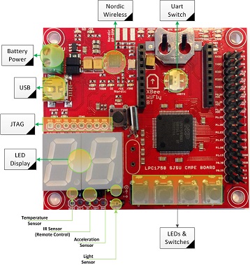 SJ-One Board Picture |
|
XBee Bluetooth.
|
 XBee Bluetooth |
Hardware Interface
Bluetooth chip communicates to SJOne board using UART interface. Pins P 0.1 and 0.0 of the SJOne board is connected to TXD and RXD pins of the CAN transceiver respectively. The CANH and CANL of the transceiver is connected to the CANH and CANL of the CAN BUS wire which is terminated with 120 ohm resistor.

Software Design
The Communication Controller's role in the car is to make communication possible between the user via an Android application and the car. The Communication Controller (bridge) receives data transmitted over the UART from the Android app. With pre-agreed "opcodes", the bridge parses the data and sends the respective information to the CAN bus. The opposite direction of the flow happens when the GPS gets a lock and the current location of the car is displayed on the app at real time. The Flow Chart below shows how this process happens at a high level.

Implementation
|
Period Init
Period 1Hz
Period 10hz
Period 100hz
|

Testing & Technical Challenges
Gibberish values while transmitting data from the app
Issue: Even though the website says the default xBee baud rate is 38400, it wasn't. It took a couple of days to figure why we had gibberish values.
Solution: UART speed should be accounted for when transmitting data from the app.
Dummy Bluetooth App for Communication development testing
Issue: Dependence on App for testing, since the development of the App and the communication controller happens in parallel.
Solution: Serial Communication Bluetooth App on Play Store for connectivity and baud rate testing. Android Studio with MapActivity template to test coordinates parsing.
UART
Issue: Data from the App is greater than the default UART queue size.
Solution: Dig into the source code and increase it.
Issue: Data loss after large transmission.
Solution: Soft reboot (at the right time).
Android Application
Design & Implementation
The app plays a crucial role in the project since it provides the checkpoints for the car's route. The app was designed for Android 7.0 (Nougat; API level 24) and requires Android 4.4 (KitKat; API level 19) or higher (up to Android 8.1, Oreo; API level 27). Google Play Services 11.0.0 or higher is required to use the Google Maps portion (for selecting the destination).
Software Design
The GUI uses fragments since it is easier to load screens within the main activity instead of moving from one activity to another. For example, there is one fragment for obstacle avoidance and another fragment for vehicle navigation (they can be accessed using the navigation drawer). We had planned to add a wireless CAN bus monitor in a third fragment but this could not be completed due to time restrictions.
The class locationPoint is user-defined and it represents each location on the map (the vehicle, the destination, and each checkpoint).
activity_main.xml
This layout is displayed after the app is launched. The parent layout uses DrawerLayout which contains a ListView (both are needed for a navigation drawer). There is also a FrameLayout for the fragments.
fragment_main.xml
This fragment is used for obstacle avoidance. This layout uses a ConstraintLayout with an ImageView, TextView, and Button. Below the ImageView and TextView is a Button used to start or stop the car manually (start will only enable obstacle avoidance mode).
The ImageView and TextView are for displaying the Bluetooth connection status on the top left-hand side of the screen. Both of these components change based on the following conditions:
- Bluetooth is disabled or enabled.
- The app is trying to connect to a Bluetooth module.
- The app is connected to a Bluetooth module on the bridge.
- The app is not connected to a Bluetooth module.


This fragment is used for navigation mode and only contains a child fragment for the map (the parent layout is LinearLayout).
The navigation drawer will display a button on the top right (within the ActionBar) when this fragment is loaded. This button is used to set the destination and put the vehicle in self-driving mode (if the user has already tapped on a location on the map).
The map shows the location of the vehicle using a green marker and a red marker is used to show the destination (if applicable). All of the checkpoints on the route are shown with a purple marker.
drawer_list_item.xml
This layout file simply defines the customized appearance of the fragment names within the navigation drawer using a TextView.
build.gradle (app)
This Gradle build file contains the Play Services version requirement (11.0.0), the target SDK version (Android API level 24), minimum SDK version (Android API level 19), the key information for generating the release version of the .apk file, the compiled SDK version (Android API level 27), and the build tools version (27.0.2).
AndroidManifest.xml
The manifest file contains the permission to access the device's Bluetooth and the key for using the Google Maps Android API (the key is required to display the Google Map within the MapView component of the fragment_main.xml layout).
strings.xml
This file stores all of the strings used in the app including the key for the Google Maps Directions API.
MainActivity.java
This is the only activity in the app and it is first loaded when the app is started. It loads the activity_main.xml layout which holds a FrameLayout. The FrameLayout is used for loading fragments.
When the app has first launched the method onCreate runs. The TTS (Text-to-Speech) object, the navigation drawer, the Bluetooth adapter, and the main fragment are created and initialized. If the device supports Bluetooth, then the monitorBluetooth method is called.
The monitorBluetooth method runs a TimerTask every 1 second to check the Bluetooth connection. If Bluetooth is disabled, then the user is asked once to enable it again. If Bluetooth is enabled, then we try to connect by running the method setupBluetooth (if we aren't connected or are trying to connect already). The ImageView and TextView are updated depending on what happens here.
The method setupBluetooth checks for a paired Bluetooth device with the hard-coded Bluetooth MAC address. If a matching device is found, then a Thread runs (our ConnectThread class).
The ConnectThread class uses a Bluetooth socket for the Bluetooth connection. Once a connection is established, then another thread executes to handle the data transfer (our class ConnectedThread). This is similar to the BluetoothChat example app that is provided by Google on the Android Developers site (and one of the examples in Android Studio).
The ConnectedThread class is used for writing data (the checkpoints) or reading data (the vehicle's location) to or from the bridge controller. When data is received it is sent to the main thread (as long as the data transfer follows a specific format).
The button in the ActionBar on the top-right of the screen will execute a FetchItemsTask object (it is only displayed when the Navigation fragment is visible). The FetchItemsTask is a user-defined class with a superclass of AsyncTask. This is where the request to get the directions is sent to Google using the Google Maps Directions API. We also manually create more checkpoints to improve the accuracy of navigation (if the checkpoints are too far then the vehicle can, but not definitely will get off course). The checkpoints are then sent over Bluetooth to the bridge with the sendCheckpoints method.
Other user-defined methods in this file include:
- writeStartStop: sends the command to manually start (for obstacle avoidance mode only) or stop the vehicle.
- sendLatLong: sends the latitude and longitude of a locationPoint object.
- sendCheckpoints: sends each checkpoint (this utilizes sendLatLong).
- getDistanceFromLatLongInM: calculates the distance between two coordinates using double values. The calculation follows the Haversine formula (as described in the Geo controller section).
When the app is closed onDestroy executes and we close the Bluetooth socket.
MainFragment.java
This is the fragment that is loaded first. This fragment contains the ImageView and TextView objects for the Bluetooth connection status and the button for starting and stopping the vehicle (starting is for obstacle avoidance only).
After onAttach runs, onCreateView executes. All of the components of fragment_main.xml are initialized and set up in onCreateView (including a click listener for the button).
The method updateStartStopButton uses the main thread to change the Button while the method updateBluetoothConnectionStatus uses the main thread to change the TextView and ImageView.
The Callbacks interface is used to call methods between the activity and the fragments.
This fragment contains the map which is initialized and set up in onCreateView.
When onResume runs (i.e. when the app is in the foreground again after being in the background), the marker for the vehicle is drawn on the map using the user-defined method addMarkerVehicle (it is redrawn if a previous marker was already set. This is done in order to get the latest data on the vehicle's location).
onMapReady runs once after the MapView is first loaded and adds the marker for the vehicle (if applicable). The click listener is also set up here so that whenever the user taps on the map the destination is set (this only happens if the car is not already on a route or the vehicle has been manually stopped).
Other user-defined methods in this file include:
- setLatLongDestination: sets the latitude and longitude for the destination (represented by a locationPoint object).
- addMarkerVehicle: adds the green marker on the map for the vehicle.
- addMarkersForCheckpoints: adds purple markers for each checkpoint used on the route.
locationPoint.java
This is a user-defined class for each location that is used in the app (each of the checkpoints, the vehicle, and the destination). The class contains a String and double field for the latitude and corresponding fields for the longitude (there are also byte array fields for both of these coordinates).
The method processLatLong() processes the latitude and longitude so that each coordinate has six decimal places. This method also calculates the byte array versions of the latitude and longitude.
The String and double coordinates are assigned using the setLatLong(double latitude, double longitude) method, which also calls processLatLong() to get the byte array versions.
The methods getMessageNumberOfBytesLatitude() and getMessageNumberOfBytesLongitude() return the number of bytes for the coordinate in the byte array format.
Implementation
This section explains the implementation of the key components of the app such as establishing the Bluetooth connection, the map (Google Maps), and the directions (using the Google Maps Directions API).
Bluetooth connection
We used Bluetooth sockets to connect the app and bridge controller.
First, we get a list of all of the paired Bluetooth connections on the Android device (these are stored temporarily in the app using the Java Set interface). Second, we check each Bluetooth connection to find a paired device that has the same Bluetooth MAC address of the module on the bridge controller (if applicable). If there is a match, then a thread (using our class ConnectThread) is created for connecting over Bluetooth.
The thread will first call the method for updating the ImageView and TextView to alert the user that we are trying to connect. Next, the thread uses the BluetoothDevice class' method getUuids to get a UUID to pass to the createInsecureRfcommSocketToServiceRecord (this is part of the same BluetoothDevice class). If the RFCOMM Bluetooth socket was created successfully, then we call the BluetoothSocket class' connect method.
If the BluetoothSocket connection was successful, then we create a new thread (using our class ConnectedThread) for handling the data transfer. The ConnectedThread creates an input stream for receiving data from the bridge and an output stream for sending data to the bridge. The run method for this class runs a while(true) loop. In this loop the InputStream class' method read is called and the loop waits until data is received.
Data transfer
The data is transferred to and from the app and bridge controller using specific formats.
Once data is received in the while loop of the ConnectedThread's run method, then we look for the termination char 'e'. If the data received is a specific length that matches what the bridge should be sending for the vehicle's location and the char 'e' was the third-to-last char in the data, then the data is sent to the main thread using a Handler.
The Handler parses the message for the number of bytes for the latitude, the number of bytes for the longitude, the latitude, and the longitude. If there is an error when converting from String to double for any of these values, then the message is discarded. If there were no errors, then we check if the vehicle is 2 m or less from the destination, we set the latitude and longitude for the vehicle's locationPoint object, and we add the new marker for the vehicle on the map. If the vehicle is 2 m or less from the destination, then the TTS (Text-To-Speech) object alerts the user with the audio "the destination has been reached".
The checkpoints are sent to the bridge in the following format (it is similar to a message received from the bridge):
Header:
- The opcode ('c')
- The number of checkpoints
Checkpoint 1:
- The number of bytes for the latitude
- The number of bytes for the longitude
- The latitude
- The longitude
Checkpoint 2-n:
- The opcode ('c')
- The number of bytes for the latitude
- The number of bytes for the longitude
- The latitude
- The longitude
Google Maps Android API
A key has to be generated in the Google API Console to use Google Maps in an Android app. This key is copied into the AndroidManifest.xml file.
Google Maps Directions API
In order to get direction, a key has to be generated in the Google API Console for the Google Maps Directions API. A request is sent to Google using a String with the following values (in the same order shown and a comma between the latitude and longitude values):
- https://maps.googleapis.com/maps/api/directions/json?units=imperial&mode=walking&origin=
- vehicle's latitude
- vehicle's longitude
- &destination
- destination's latitude
- destination's longitude
- &key=
- Google Maps Directions API key
Testing & Technical Challenges
Most of the basic concepts for Android development were already familiar from past experience (i.e. CMPE 277). The main challenge was establishing the Bluetooth connection and handling the data that is received over Bluetooth (we came up with specific formats for messages between the bridge and app).
Bluetooth connection
One of the initial challenges was finding out how to connect to the module over Bluetooth. A Bluetooth connection requires a UUID and the easiest way to get a UUID is to get one from the Bluetooth radio itself (the device name refers to the BluetoothDevice object instance that we are using):
device.getUuids()[0].getUuid()
JSON
The directions can be returned by Google in a JSON object (the alternative option is XML). It can be difficult to parse JSON objects if you aren't familiar with doing this task but there are resources online that are helpful (including the Google Maps Directions API website/guide).
Conclusion
This project served as a great source of learning as it was challenging to develop and integrate the features of the self-driving car. It gave us a great sense of achievement in having completed the project by working together as a team.
By completing this project we all learned how to use an important version control tool in development-Git. Git allowed us to keep track of changes to the master branch as well as branches for each of the controllers and the Android application. We also got hands-on experience with the CAN bus protocol which is useful for any embedded system in the automotive industry as well as the DBC file format and the BusMaster CAN tracing tool. We were required to complete unit testing for each of the controllers. Learning Test Driven Development (TDD) was a challenge but overall it was a great experience for us because developing this way reduced time spent on debugging.
Project Video
https://www.youtube.com/watch?v=YiA8Qv2gooY&feature=youtu.be
Project Source Code
References
Acknowledgement
We would like to express our gratitude to Professor Preetpal Kang for generously sharing his time and knowledge with us and guiding us through the completion of this project. We would also like to thank the ISA team for their valuable advice and constructive feedback.
References Used
PID Control
LCD
Android GUI
Bluetooth
Google Maps
Datasheets
[1] XL-MaxSonar-EZ4 Ultrasonic Sensor
[2] Parallax Ping Sensor
[3] 4D Systems LCD
[4] CAN Transceiver
[5] GPS Module
[6] Compass Module