F18: Catch me if you can
Contents
Grading Criteria
- How well is Software & Hardware Design described?
- How well can this report be used to reproduce this project?
- Code Quality
- Overall Report Quality:
- Software Block Diagrams
- Hardware Block Diagrams
- Schematic Quality
- Quality of technical challenges and solutions adopted.
Project Title
Catch Me If You Can
Abstract
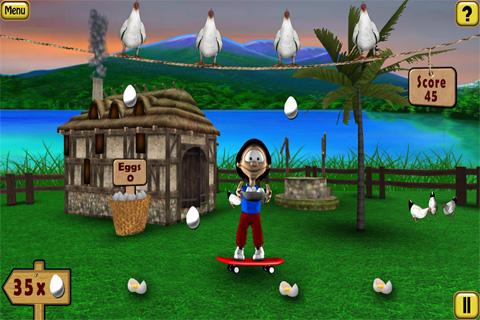
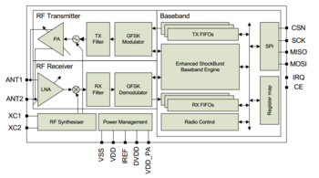
"Catch me if you can" is a fun game where the user must be attentive and agile enough to catch the randomly dropping eggs from above into a basket with increasing difficulty levels for an intriguing experience. This is all displayed in the LED matrix acting as the screen. The system will consist of two SJ1 boards, one used as a game console with which user will try to catch the eggs by moving it in the required orientation. The other board will control the display module that displays the graphics of eggs falling and also the basket movement. The display module shall communicate with the game console via RF Nordic transceiver. There will be game sounds produced by the display module board for various events during the game like entering a new level.
Objectives & Introduction
Objective
To develop an Embedded system in the form of a 2D game involving a Matrix LED display acting as the Human Machine Interface to guide the player along the way while playing the game. This project aims at integrating micro-controller peripheral drivers and the application software in a meaningful way, where the accelerometer data is sent out from a node via wireless Nordic transceiver to control slider movement on the other node to control the game according to player's performance.
Introduction
The Project consists of three main modules:
Console Module: It consists of accelerometer on SJ one board. Calibrated board orientation and switch pressed status is sent to the Display Module via Wireless Module.
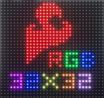
Display Module: It is responsible for controlling 32*32 LED Matrix and Piezo buzzer interfaced to SJ One Board.
Wireless Module: This establishes communication between Display and Console module.
About the game
- Player should collect the eggs into the basket which are shot from the canon.
- Press switch on the console (SJOne board) to start the game.
- Tilt the console left or right to move the basket.
- Collect the eggs falling of randomly.
- Avoid red objects, if caught Game Over, else continue to collect eggs till the end of level.
- 6 eggs need to be caught to progress to next level.
- Yellow egg is a freebee where the basket expands to help the player.
- Level 2 and 3 has rising water level on each egg miss which increases the difficulty of the game.
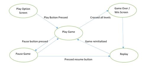
- Player can play and pause the game anytime and resume from where he paused.
Team Members & Responsibilities
- Aquib Abduljabbar Mulani
- Wireless chip TX driver/application and calibrating accelerometer.
- Kailash Chakravarty
- RGB LED 32x32 matrix driver and game application code.
- Nandini Mandya Shankaraiah
- Audio output and Wireless chip RX driver/application.
- Rishabh Sheth
- PCB design.
- Swanand Sapre
- Console and Game design and application code.
Schedule
| Week# | Date | Task | Status | Actual Completion Date |
|---|---|---|---|---|
| 1 | 10/16/2018 |
|
Completed | 10/25/2018 |
| 2 | 10/30/2018 |
|
Completed | 11/05/2018 |
| 3 | 11/06/2018 |
|
Completed | 11/13/2018 |
| 4 | 11/13/2018 |
|
Completed | 11/16/2018 |
| 5 | 11/20/2018 |
|
Completed | 11/22/2018 |
| 6 | 11/27/2018 |
|
Completed | 12/1/2018 |
| 7 | 11/30/2018 |
|
Completed | 12/06/2018 |
| 8 | 12/04/2018 |
|
Completed | 12/11/2018 |
| 9 | 12/11/2018 |
|
Completed | 12/18/2018 |
Parts List & Cost
| Sl No | Parts | Seller | Quantity | Price |
|---|---|---|---|---|
| 1 | SJOne LPC1758 Microcontroller Board | Preetpal Kang | 2 | $160 |
| 2 | RGB LED Matrix Panel - 32x32 | Sparkfun | 1 | $55.6 |
| 3 | Piezo Buzzer | Amazon | 2 | $1.5 |
| 4 | Accelerometer | On board | 1 | NA |
| 5 | Switches | On board | 4 | NA |
| 6 | Portable Power Supply | Local seller | 1 | $5 |
| 7 | RF Nordic | On board | 1 | NA |
| 8 | BOM / PCB components | Moser | - | $20 |
Design & Implementation
Hardware and PCB Design
PCB Design
PCB is an important part of the embedded system, it is certainly true for this project as it reduced wire complexity and gave independent power to our circuit. There are many softwares available for PCB design, among them Eagle and KiCAD are more popular and both software are free for students. We chose KiCAD (v5.10.0) for PCB design over Eagle because, it is opensource so we din't have to worry about the license. The second reason was that, all of our team members was new to PCB design so the learning curve was same for both software but we found a good tutorial series for KiCAD on youtube ( KiCAD tutorials ). KiCAD has its own issues which are discussed in the issue section of this wiki.
The steps involved in the PCB design process are described in the next section.
Schematic Design:
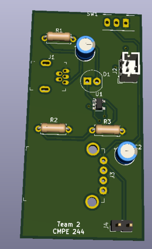
Our project can be divided into two main circuits, first is game display circuit and second is a console circuit. We decided to design separate PCB for both circuits as doing so can make wiring easy and improve the user experience.
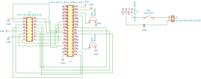
Display PCB schematic:
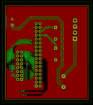
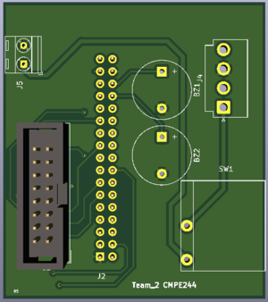
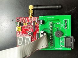
Display PCB has two independent circuits. One circuit is to connect SJOne board to LED panel connector and with two piezo buzzers. While another circuit is to connect one unused power cable of LED panel to SJOne board so that we don't have to power SJOne board from PC while we are playing the game. Our preliminary idea was to make this PCB, a Arduino kind of shield but for SJOne board.
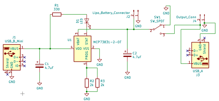
Console PCB schematic:
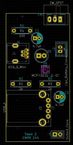
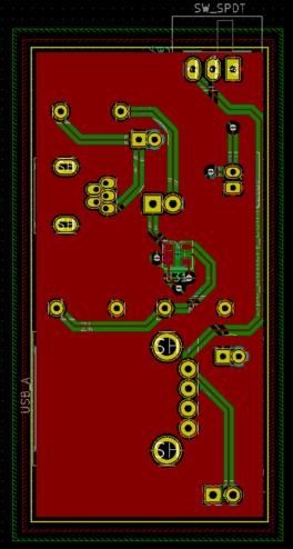
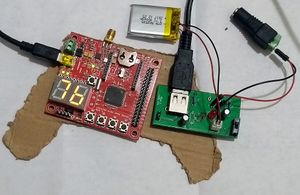
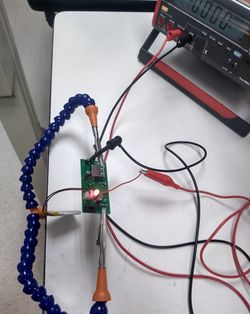
In this game, console is used to move the basket to catch fast falling eggs and if there were any wires attached to console then it is very inconvenient for the user to play. so, we decided to make PCB which can charge battery and power the console while the user is playing. As shown in figure, the heart of the circuit is microchip's MCP73831 LiPo battery charging management IC. One LED is connected to it's Status Pin which glows when the battery is charging. A mini USB B port is used to connect to power resource (PC or any 5V mobile charger)via USB cable to charge the battery. while playing the game, the user must connect USB A port to SJOne Board's mini USB B port. To use the console on battery power user must turn on/off switch.
PCB Layout:
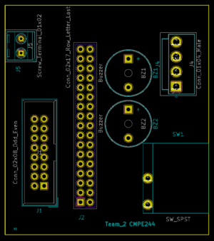
After schematic design, the most important step is to connect the PCB layout. In KiCAD components is not automatically associated with it's PCB footprint, so it's user's responsibility to connect right PCB footprint with the right components. In our case, we did not have the footprint of JLC connector and Rocker switch. so, we created it in a different window and saved it. The amazing feature of KiCAD is once we have done with PCB layout we can visualize PCB in 3D by pressing just one button. Below are actual screenshots of both, PCB layout & their 3D model.
Display PCB layout:
Console PCB layout:
PCB manufacturing and soldering:
We chose JLC PCB to manufacture our PCB because, it is the cheapest and convenient option available for any prototype PCB manufacturing. It just cost us $2 for quantity of 10 PCB and $17 for shipment. We received manufactured PCB in just 5 days. We order components from Moser the total BOM cost of both PCB is approx $25 including shipment. Followings are actual photos of manufactured & assembled PCBs.
Hardware Interface
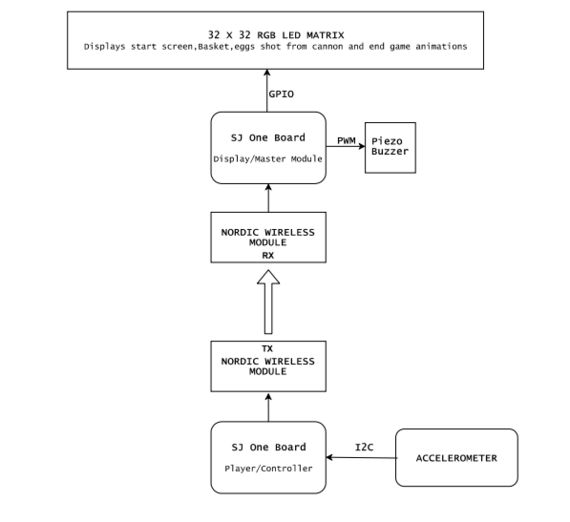
Hardware design diagram above gives an overview of the entire system which consists of the two SJ-One controllers: one board is used as Control Module and other board is used as the Display Module.
- The Console Module uses the onboard accelerometer on SJ-One which is interfaced via I2C protocol. The calibrated accelerometer values are then used to determine the basket position on the LED Matrix.
- The Display Module SJ-One board is used to control a 32*32 RGB LED Matrix.This matrix displays the basket, eggs shot from the cannon.The movement of the basket is as per the orientation value received from the Control Module, through Wireless Module. It also consists of Peizo buzzer which is controlled via PWM pin.
Software Design and Implementation
Display Module
RGB LED Matrix:
The Human Machine Interface is a display which is composed of 6mm pitch 1024 RGB LEDs arranged in a 32x32 matrix. 32 rows of the matrix is divided into 16 interleaved sections. Here the first section is the 1st and 16th 'row' (32 x 2 = 64 RGB LEDs), the second section is 2nd and 17th 'row' and so on. On the PCB is 12 LED driver chips. These are like 74HC595s but they have 16 outputs and they are constant current. 16 outputs * 12 chips = 192 LEDs that can be controlled at once, and 64 * 3 (R G and B) = 192. So now the design comes together. We can have 192 outputs that can control one line at a time, with each of 192 R, G and B LEDs either on or off. The LPC1758 controller selects which section to currently draw (using A, B, C and D address pins - 4 bits can have 16 values). Once the address is set, the controller clocks out 192 bits of data (24 bytes) and latches it. Then it increments the address and clocks out another 192 bits, etc until it gets to address #15, then it sets the address back to #0. To light up an individual pixel, appropriate row value is loaded on to the address pins A,B,C & D, Clock is set out to traverse the row and when required pixel is reached, the latch is set high to turn ON the LED. The hardware interface to the LED Matrix uses GPIO for all data and control lines. A GPIO clock is toggled to shift in data sitting at the Matrix's 6 data ports.
| SJ One Board Pin | Name | Description |
|---|---|---|
| P0.0 | addrA | Address Input A |
| P0.1 | addrB | Address Input B |
| P2.6 | addrC | Address Input C |
| P2.7 | addrD | Address Input D |
| P1.29 | Latch | Shift in row data/Active High |
| P1.28 | Output Enable | Turn on selected rows/Active Low |
| P1.19 | Clock | Shift clock |
| P1.22 | R1 | Top half red data |
| P0.26 | G1 | Top half green data |
| P1.23 | B1 | Top half blue data |
| P1.30 | R2 | Bottom half red data |
| P1.31 | G2 | Bottom half green data |
| P2.5 | B2 | Bottom half blue data |
Piezo Buzzer:
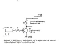
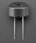
Piezo electric buzzer are high performance buzzer that employ piezoelectric elements and are designed for easy incorporation into various circuits. These buzzers are designed for external excitation, the same part can serve as both a musical tone oscillator and a buzzer. In our project we are using this device to create musical tones by varying the operating frequency.The different range of operating frequency are generated from PWM peripheral. Different range of frequencies are maintained as constants ,these constants are fed to PWM,which generates square wave. The output of the PWM is driving the Piezo buzzer.
Code snippet for creating musical tones by varying frequency:
int fire[]=
{
		550,/*twice the freq of this and use always tempo as 40 */
		404,
		315,
		494,
		182,
		260,
		455,
		387,
		340
};

void fire_sound_level(void){
	 for(int i = 0;i < 8;i++)
		 {
		 	 uint8_t tempo = 40;
		 	 	 while(tempo)
		 	 	 {
					pwm.SetFrequency(fire[i]*2);
					pwm.SetDutyCycle(pwm.k2_1,50);
					pwm.PwmEnableMode(true);
					tempo--;
		 	 	 }
		 }
		 pwm.PwmEnableMode(false);
	}
Control Module
Accelerometer:
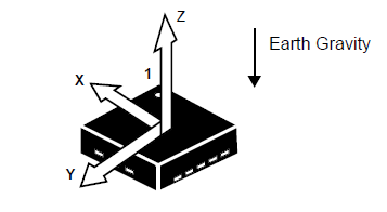
| In our project,we have calibrated the accelerometer based on the values of X,Y and Z co-ordinates corresponding to different orientations of the accelerometer to control the horizontal movement of the Basket int the game to catch the eggs on the screen. This has also helped us decide and control the speed of the basket. As shown in the code snippet below the x movement on the right is determined based on the x co-ordinate and the console sensitivity which you wish to set.Similarly movement on the left can also be calculated for further use. |
Code snippet for Accelerometer Calibration:
if (((x_coordiante > px_coordiante + CONSOLE_SENSITIVITY) && (x_coordiante <= CONSOLE_TILT_RANGE) ))
{
        boardOrientation=left;
        bskObj.speed=BASKET_SPEED;
        px_coordiante=x_coordiante;
}
    //left
    else if((x_coordiante<px_coordiante-CONSOLE_SENSITIVITY && x_coordiante>=-CONSOLE_TILT_RANGE))
{
        boardOrientation=right;
        bskObj.speed=BASKET_SPEED;
        px_coordiante=x_coordiante;
}
else if(x_coordiante>CONSOLE_TILT_RANGE ){
        boardOrientation=left;
        bskObj.speed=BASKET_SPEED;
}
else if(x_coordiante<-CONSOLE_TILT_RANGE ){
        boardOrientation=right;
        bskObj.speed=BASKET_SPEED;
    }
else
{
        boardOrientation=invalid;
        py_coordiante=y_coordiante;
}
Wireless Module:
Code snippet for Wireless Transmitter:
struct pckt
{
    int16_t x;
    int16_t y;
    int16_t z;
    int16_t buttonPressed=0;
};
void WirelessTx(void *p)
{
       while(1)
       {
           pckt var;
           var.x = AS.getX();/values from accelerometer*/
           var.y = AS.getY();
           var.z = AS.getZ();
           pckt var;
             while(1)
             {
                 if(SW.getSwitch(1))
                 {
                     var.buttonPressed=1;
                     vTaskDelay(300);
                 }
                 else if(SW.getSwitch(2))
                 {
                     var.buttonPressed=2;
                     vTaskDelay(300);
                 }
           wireless_send(REM, mesh_pkt_nack,(pckt*)&var, 8, 0);
           vTaskDelay(50);
             }
       }
}
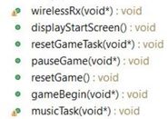
Code snippet for Wireless Receiver: void wirelessRx(void* p)
{
while(1)
{
mesh_packet_t rcvPkt;
int timeout_ms = 50;
if(wireless_get_rx_pkt(&rcvPkt, timeout_ms)){
iphObj.x_coordiante = (int16_t)(*((uint16_t*)(rcvPkt.data+0)));
iphObj.y_coordiante = (int16_t)(*((uint16_t*)(rcvPkt.data+2)));
iphObj.z_coordiante = (int16_t)(*((uint16_t*)(rcvPkt.data+4)));
iphObj.buttonPressed= (int16_t)(*((uint16_t*)(rcvPkt.data+6)));
if(iphObj.buttonPressed==1 )
{
xSemaphoreGive(playPauseHandler);
}
else if(iphObj.buttonPressed==2 )
{
xSemaphoreGive(resetGameHandler);
}
}
vTaskDelay(50);
}
}
Tasks and Flow Control
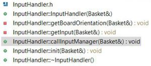
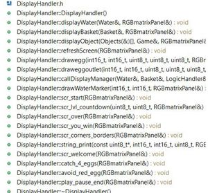
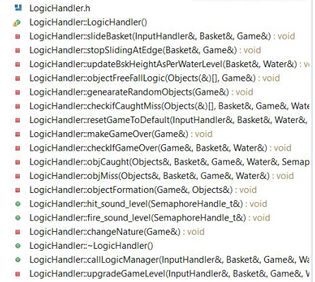
'Input_handler:' This is class, which contains all the functions which controls the position of the basket. Which is in turn depends on the console unit orientation value received from wireless task. This task also receives status of button press from the console unit. The values are received as a structure. Wireless task checks for button press and accordingly changes the state of game.i.e for button 1 press it pauses the game and for button 2 press it restarts the game. The accelerometer values are used to calibrate the basket horizontal movement.Depending upon the x-axis values of console the basket slides horizontally. Display_handler: We have implemented the various functions to display the components used in our Game. It uses GFX matrix library to draw the shapes and pixel. Objects used in our game includes Baskets,Eggs,Cannon and Water. Apart form Object display Handler also has functions to implement the screens used in our Game like-Play/Pause screen,Game Over Screen,Win Screen. Game_Begin: This is a task which divided into Logic Handler, Input Handler and Display Handler. Input Handler read the input,Logic Handler implements various algorithms to generate eggs with random behavior,checks for game Over condition,sliding the basket depending upon the direction received from Input handler,speed of sliding ,Logic to determine the catch or miss of Egg and increment the water level on every miss.Display Handler deals with displaying objects on screen. Each handler class have its manager functions which calls all the private functions of respective handler. From the game Task we call these manager functions of all the handlers.Basic Game theory is to check the input,update the logic and display. we are implementing same thing using handlers for display,logic and input. Tasks in Console Module : Transmitter Task: This task periodically transmits the orientation values and button press status to the display module. Task Priority :1 (could be anything as it the only task running in the console). Testing & Technical ChallengesIssues, Challenges and solutions to get past them1. RGB LED Matrix Display driver Porting Adafruit LED driver, which is AVR microcontroller compatible into LPC was challenging because the library was not compatible with LPC1758 micro-controller. As a result, initially all the LEDs were getting turned on. Plenty of changes were done in the existing Adafruit library after which the driver was working as expected. Some of the changes were - to map the LPC GPIOs to LED matrix pins. This was challenging because choosing the pins also mattered for PCB design, which we were unaware until we started to design PCB. We had to remap the LPC GPIO pins to LED matrix as per PCB wiring convenience again. In addition to the basic API functions available, we had to develop many new APIs which were specific to the game using the bitmap to create various re-usable objects. So basically we had to migrate the whole library from AVR to LPC1758. 2. Nordic Wireless In Nordic Wireless, the transmitted data was received only once, despite the transmitter transmitting data continuously. This was because vTaskStartScheduler() API was used by us.The scheduler_start() API was the right API to be used for Nordic Wireless to function properly. Once we implemented the queue to collect orientation and switch status, we saw a delay in data reception. This was due to usage of scheduler_start() which initializes the wireless_service task. 3. Peizo Buzzer Determining the range of audio frequencies which would be audible and sensible was challenging.After days of trail and error method we found the range. After finding the range, the problem we encountered was with switching frequencies. Drastically varying frequency of PWM will cause sound produced by Peizo unpleasant.In order to overcome this we had to vary frequency in small steps. Say you want to change frequency from 410 to 510. do it in steps 410,420,430 soon.One more important thing to verify is the whether the frequency generated by PWM peripheral matches your expected frequency, do verify it with logic analyzer once before writing the music tone libraries. 4. Playing tone at all stages of the Game Display of the objects being delayed, when different tones were played in the back ground. We did not understand what was causing this issue. Due to time constraints we could not further debug more on this. To overcome this would be challenge to us in the near future. 5. PCB issue For some of the components, KiCAD library was not present so we have to develop our own components and footprint library. One such components was Rocker Switch in display PCB. Designing footprint for this component was really hard as the manufacturer did not give clear measurement/dimensions for the footprint. When we received the components, legs of the switch was slightly thicker than described in datasheet. To overcome this we had to file metal legs in order to fit the switch in PCB. Our PCB is of 1.6mm thickness while our USB Mini B connector was designed to fit into 1.5mm thick PCB. This made soldering the connector tedious. SMD IC component in our console PCB which was very difficult to solder by hand. During soldering, we accidentally shorted some pins due to which our console PCB got burnt and we had to re-order the components again. 6. Task Priority First thing is configuring task priorities and state machine for game state was challenging. We have a total of five tasks. To decide the priority of each task was time consuming, as we dint want the tasks to interfere with the game task which is of lower priority.To over come this we measured the game task execution time and used this time as a block period for higher priority tasks. Another issue was that the game slowed down as the game level progressed. After debugging, we found out that the issue was due to high RIT_Interrupt rate. The RIT interrupt was very frequent, as a result more of the CPU time was consumed in context switching to interrupt, which slowed down the other tasks. To over come this we reduced interrupt rate by a factor of 20 ,with which the issue was resolved without affecting the LED display refresh rate. PCB module TestingWe tested LED display with SJOne board using breadboard connection to make sure that there should not be any connection issue in final PCB design. Ones we received our PCB first tested PCB's continuity to make sure that all connections and traces are as expected. Also after soldering components, we did the continuity testing. Console circuit testing was not possible before we design and received PCBs as we don't have main IC and it is available only in SMD. Ones we solder the whole PCB and gave power PCB got burnt, after rigorous testing and debugging we found that we used SPDT switch which connects battery's positive terminal to ground. We solve this problem in next iteration by not connection one lag of SPDT switch after that it worked fine. We configured our IC to charge 400 mAh battery at the rate of 80mAh (preferred configuration in the datasheet). So It takes approx 5h to charge battery ones it fully discharged. We tested our circuit with two full charging-discharging cycles and everything worked as expected.
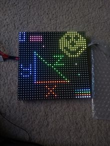
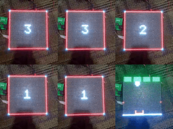
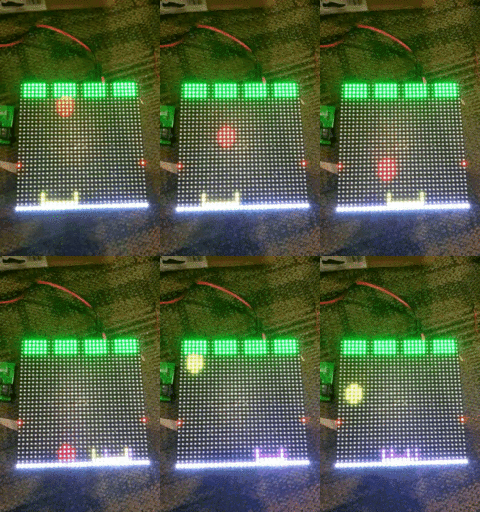
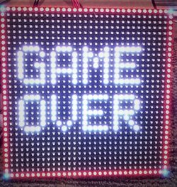
Display Module and Game TestingSteps of Testing1) The RGB LED Display was tested for basic objects like rectangle, line, characters. The flickering of the screen was observed initially with a slow screen refresh rate of anything slower than 5khz. So the refresh rate was fixed at 5khz. Below are snapshots of some of the screens tested. 2) Wireless module was tested by sending a single byte of data. Every time the byte was transmitted, we printed the transmitted value on the Hyperload terminal. Similarly at the receiving SJ one board, we printed the received value. Once this was achieved ,then we reapeted the same procedure with the actual data packet.This whole procedure ensured that the console module is working fine. 3) Once, we had the console module ready, we started integrating the display module and console module. Once we integrated ,we checked for the basket movement while changing the board orientation. Until we had the smooth movement of the basket object on the screen, we continued to finely tune the calibration for accelerometer values. 4) After fine tuning the calibrations, we moved on to test out game algorithms, where the display screen was rigorously tested by playing the game continuously, reversing the console board and trying to see whether display responds. All the stages of game algorithms (the handlers mentioned the software design ) the start screen,end screen, count down screen and display during game was verified. 5) The game algorithm i.e. system testing was done where we tested the screen navigation sequence, difficulty levels of the game (it should not be too easy to win and not too hard to win either). Also every member was asked to play the game for a through testing for robustness of the algorithm. Negative test cases were also tested like pressing the key randomly and likewise.
ConclusionAt the start, project was a jigsaw puzzle. We only had pieces of knowledge and unaware of how to tailor it to solve the puzzle. Well we are successful in implementing our idea of building a game. This project has helped us to gain practical exposure in building a real time embedded system. This project gave us a platform to utilize all LPC drivers and Free RTOS knowledge which we learnt in our course work and what are the key things to consider while building a real time system. We are thankful to Preet, who motivated and guided us through out the course work. Project VideoProject CodeGitHub Link : Catch_Me_If_You_Can ReferencesAcknowledgementWe would like to thank our Professor Preetpal Kang for all his awesome lectures and explanations of the embedded system topics, they could not have been explained any better than this! Not only did we enjoy working on this project but it also gave us an overall learning experience and precious life lessons. We would also like to thank the ISA members for always being around and ready for helping whenever required. References Used[2] [1] [3] Low_Powered_Mesh_Network_stack [5] [2] AppendixYou can list the references you used. |
