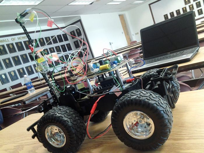
S12: Self Drive Car
Contents
Self Drive Car
Abstract
The aim of the project was to build an autonomous car, also known as self-driving car. The vehicle is capable of sensing its environment and navigating its own path using sensors. The advanced control system, such as ARM7 processor integrated with FreeRTOS, interprets the information received by the sensors to identify an appropriate navigation path as well as obstacles.
Objectives & Introduction
- Interfacing ultrasonic sensors with ARM7 microcontroller.
- Interfacing motor controller boards with ARM7 microcontroller.
- The car will be able to control its speed by itself.
- At the time of the start, the car will make ignition sound.
Team Members
- Shweta Nehra
- Rishabh Sareen
- Himanshu Saini
Parts List & Cost
| Part Name | Quantity | Cost |
|---|---|---|
| LPC2148 Microcontroller | 1 | $60 |
| Motor Controllers | 2 | $36 |
| MP3 Development Board | 1 | $60 |
| Car | 1 | $20 |
| SRF02 Ultrasonic Sensor | 3 | Provided by Preet |
| Power Supply | 1 | $10 |
| Jumper Wire | 4 pack | $24 |
| Screws, Washers | 1 box | $12 |
| Battery 2500mah (7.6V) | 1 | $15 |
| Wire Wrapping Board | 1 | $12 |
| Speaker | 1 | $10 |
| Lego Parts | 1 pack | $5 |
| Header Pin | 1 pack | $5 |
Design & Implementation
Hardware Design
Hardware Interface
PWM Driver
PWM uses a timer which is set and reset as per the values of match registers and timer counter. Timer is programmed to count the peripheral clock cycles. This count is varied in the programmable prescaler register PWMPR. There are in total 7 MATCH registers. Basically, it generates interrupts or perform operations as a timer value is reached i.e., Timer counter reaches a MATCH register value.
Initializing PWM driver:
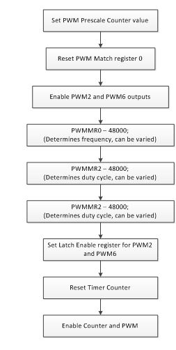
- The first register is needed to set in PWM driver is PWMPC (Prescale Counter Register). PWMPC is a 32-bit Prescale counter controls division of PCLK by some constant value before it is applied to the PWM Timer Counter. The above mentioned constant value is stored in a register called, PWMPR (PWM Prescale Register). When the PWMPC value is reaches the value stored in PWMPR, the PWM Timer Counter is incremented and the PWM Prescale counter is reset on the next PCLK. The requirement of the project is to increase PWM Timer Counter on every clock cycle of PWMTC; therefore, PWMPR register is set to zero.
- The second register is needed in PWM driver is PWMMCR (PWM Match Control Register). The PWMMCR is used to control various operations when one of the PWM Match Registers matches the PWM Timer Counter. According to the project requirement, bit number one is selected, which is PWMMR0R. The bit number one is set to ‘1’ so that when PWM Match Register matches PWM Timer Counter then PWMTC will reset.
- The third register is needed in PWM driver is PWM Control Register (PWMPCR). The PWMPCR register is used to enable and select the type of each PWM Channel. As per the project requirement, single edge PWM is used. Since PWM2 and PWM6 pins are used for back and front wheel respectively; therefore, PWM2 and PWM6 outputs are enabled on bit number 10 and 14 of PWMPCR register. The bit number 2 and 6 are set to ’0’for single edge output.
- The fourth register is needed in PWM driver is PWM Match Register (PWMMR). The 32-bit PWM Match Register values are continuously compared to the PWM Timer Counter Value. When the two values are equal, actions can be triggered automatically. PWMMR0 register is used to set the frequency as 1Khz. Since the peripheral clock is 48Mhz; therefore the PWMMR0 is set at 48000. When 48Mhz will be divided by 48000 then the pulse produced will be at 1Khz.
- Match registers 2 and 6 are used to set the duty cycle of back and front wheel respectively. Initially, they are set to 48000, which mean duty cycle is zero percent. As the value of match registers 2 or 6 will decrease to zero, the duty cycle will increase to 100 percent.
- The fifth register is needed in PWM driver is PWM Latch Enable Register (PWMLER). The PWM latch enable register is used to control the update of the PWM Match Register. So, whenever the PWM match registers are updated, PWMLER should be used just afterwards.
- The fifth and last register is needed in PWM driver is PWM Timer Control Register (PWMTCR). The PWM Timer Control Register is used to control the operation of the PWM Timer Counter. This register should be set at the last of the PWM driver. First, the bit number 1 of PWMTCR should be enabled; then, the bit number 0 and 1 should be enabled by writing ‘1’.
- The following flowchart describes these steps in brief.
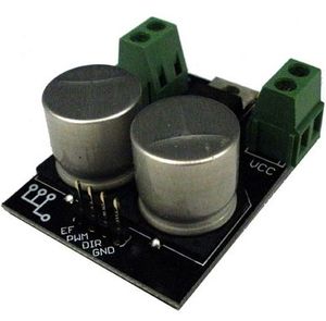
- 5A Motor Controller
Two 5A motor controllers are used in order to activate the two motors: Front motor and Back motor. These motor controllers enable the car to run in different directions:
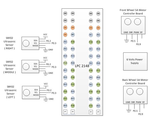
- Front Motor: It is controlled by one of the motor controller which decides whether to turn right, left or center. The PWM pin is connected to PWM2 on LPC2148(Figure 1). The direction is determined by the DIR pin which is connected to any of the GPIO pin on LPC2148.
- The GPIO pin chose on LPC2148 is first set to be output using IODIR.
- It is set or clear by writing 1 to IOSET or IOCLR respectively in order to set the direction.
- Back Motor: It is controlled by another motor controller which enables it to run in the forward direction. The PWM pin is connected to PWM6 on LPC2148 (Figure 1). Also, the duty cycle set in PWM driver as mentioned above sets the speed of the back wheels which will enable the car to move with that particular speed.
I2C Driver
- About I2C: Inter Integerated Circuit
It is also one of the communication busses in embedded systems but it is an open collector bus. Its architecture consists of multiple masters and multiple slaves. In order to communicate with a device a master needs to establish a start instruction first and then only it will be able to send the data. I2C architecture has 9 bits of data in a single frame. Last bit is for acknowledgement.
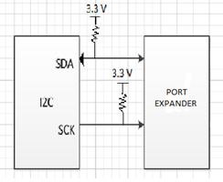
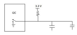
I2C acts as an open collector bus and hence, prevents short circuit. All the devices that are connected acts as capacitors. Data might be corrupted in I2C communication but there will be no short circuit. But, due to the devices acting as capacitors the speed of I2C is much slower.
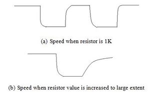
Resistor value must be at least 1K as if it will be less the current will be more and hence the devices will not be able to sink that much amount of current. But, we cannot even increase the resistor value a lot because of the speed issue. Increasing the resistor value to a large extent will result into very slow speed.
- Initialization of I2C
- We were required to write functions for Initializing I2C transaction, read device register and write device register.
- First of all a few Global variables were declared and initialized so as to execute the I2C function asfollows:
- //Address of the device to be interfaced
- char mSlaveAddress = 0;
- char mTrxLen = 0; //Transfer Length
- char mSlaveReg = 0;
- char mSlaveData = 0;
- //Checks whether to Read or Write
- int mChkStatus = 0;
- Then, Initialization required a very few steps which made use of bit-manipulation. The I2C transaction needs to have two lines SDA i.e., I2C Serial data and SCL i.e., I2C Serial Clock so, we needed to make the bits 5:4 as 01 and 7:6 as 01 for SCL0 and SDA0 respectively using PINSEL0:
- PINSEL0 &= ~(0xF0);//Clearing the bits
- PINSEL0 |= 0x50;//Setting them to 0101
- Then, I2C Control Set Register, I2CONSET has its bit 6 as the I2C enable bit in order to interface it with the port expander.
- I2CONSET = (1 << 6); //Set bit6 to 1
- The clock rate also needs to be calculated and set. This formula is used to calculate the clock rate.
- PCLK / i2cFrequency;
- I2C SCL High and low duty cycle registers were used in order to count the high and low periods of the clock in order to optimize I2C.
- I2C_I2SCLH = DividerRegs / 2;
- I2C_I2SCLL = DividerRegs / 2;
- After the initialization next step was to write Read and Write functions. Both the functions included polling until the I2C Control Set Register, I2CONSET has its bit 3 to be 0 i.e., I2C interrupt clear so that the operation could break and start the state machine in order to perform the specific operation whether Read or Write.
- while (1)
- {
- if (I2CONSET & (1 << 3))
- {
- break;
- }
- }
- status = i2c_StateMachine();
- For the ReadDeviceRegister and WriteDeviceRegister functions we need the following global variables to be defined as follows:
- mSlaveAddress = deviceAddress;
- mSlaveReg = registerAddress;
- mSlaveData = 0;//In case of Read
- mSlaveData = valuel;//In write
- mTrxLen = 1;
- mChkStatus = 1;//In case of Read
- mChkStatus = 0;//In case of Write
- Here, mCheckStatus variable is to identify in the state machine whether the states should transition for Read operation or Write Operation.
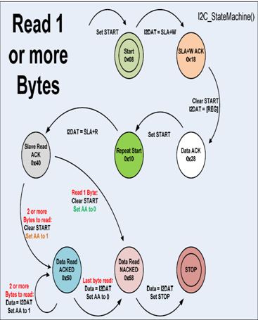
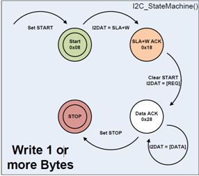
- Next, was the state machine whose state diagrams for Read (left) and Write (right) are given below.
SRF02 Ultrasonic Sensor
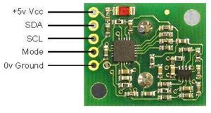
- Connect the SDA and SCL pins to P0.9 and P0.5 of LPC2148 (Figure 1) which are configured to be SDA and SCL lines in I2C driver.
- For SRF02 Ultrasonic sensor the MODE pin is left unconnected for I2C mode.
- The default address of the sensor is 0xE0.
- Address is changed for another SRF02 Ultrasonic sensor as the sensors for left and right direction must have different address.
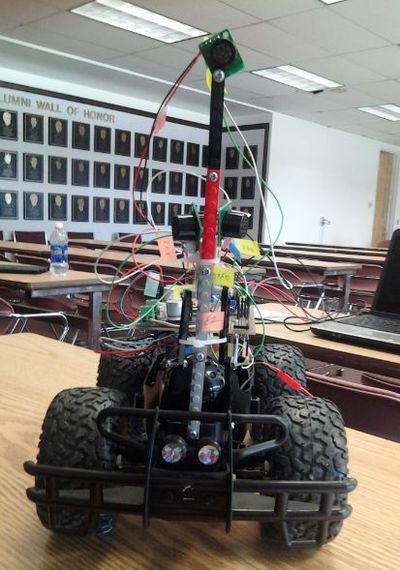
The following figure shows the placement of three SRF02 Ultrasonic sensors on the car:
Software Design
Implementation
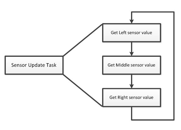
We have two tasks:
- Sensor Update Task
- Movement Test Task
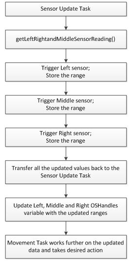
We have one function which triggers each of the three SRF02 Ultrasonic sensors and then, updation of these values is done in the Sensor Update Task. These updated values are then used by the Movement Test Task which implements a state machine which lets the car know in which direction to move on when it encounters an obstacle in a particular direction.
SRF02 Ultrasonic Sensor
- Working of SRF02 Sensor:
The SRF02 has 6 registers. As per the project requirement, only three registers are used, such as register 0, 2, and 3. The register zero is used to start a ranging session. Register zero cannot be read. The ranging session maximum lasts for 65ms. It means that if obstacle is 2 or 3 meter far away, then ranging session will take 65ms. However, the obstacle is nearby, such as 100cm or 200cm, and then the ranging session will take less than 65ms. Therefore, instead of suspending or delaying the task for 65ms will delay the alertness of the car.
In order to overcome from above mentioned problem, Mr. Preet helped us to write a more intelligent I2C driver. Instead of waiting 65ms, the I2C driver will keep checking after each 5ms that device (sensors) is ready to provide data or not.
Thus at the time of triggering the sensor, three variables are provided to I2C driver, such as address of the device, register zero, and return result format ( inches, centimeter or microseconds). Once the range is read from the register 2 and 3 of the device, then it is stored in a 32-bit size variable, such as “int”. Then afterwards same procedure is repeated for the rest of two sensors.
Once the current range between obstacles and the car is collected, then it updates the “oshandle” variables left, right, and middle. Once the “oshandle” variables left, middle, and right updated then “movement task” can access it to further process the data.
- I2c Bus Address Change of SRF02 Sensors:
To change the I2C address of the SRF02, there should be only one SRF02 on the bus. The default address of SRF02 sensors are 0xE0. The I2C bus address can easily be changed just by writing 3 sequence commands in the correct order followed by the address. For example, to change the address of a sonar currently at 0xE0 (the default shipped address) to 0xF2, write the following to address 0xE0; (0xA0, 0xAA, 0xA5, 0xF2 ). All three sequences must be sent to the command register at location 0, which means 4 separate write transactions on the I2C bus.
- How Sensors Control Speed of the Car:
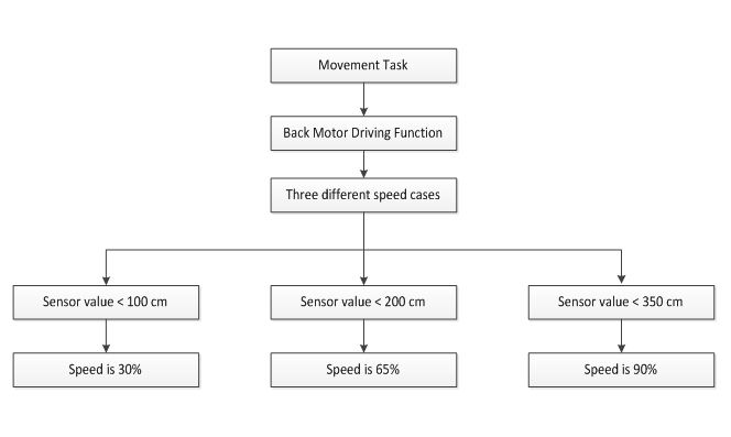
Once the oshandles variables in “SensorUpdate” task is updated with the current ranging values, then the “movement” task can easily access left, middle, and right sensor values. The middle sensor is the one which controls the speed of the car. The back motor driving function continuously checks for middle sensor values. There are three different speed cases in the back motor driving function. Whenever the middle sensor values matches to any one of three cases; the speed of the car is set to that particular speed.
Sensor Update Task
Three SRF02 Ultrasonic sensors are configured to detect any obstacle in danger limit i.e., the car needs to turn in the safe direction. One is for detecting left obstacles, second for the middle obstacles and third one for the obstacles in right. The direction of the car depends on these three primary values updated by these sensors at regular intervals of a few microseconds. Three danger values are set so that the direction of the car can be changed to the safe zone where car can move without hitting any obstacle. Thus, we have interfaced two tasks which will work concurrently. First one is the sensorUpdate task which will keep on updating the distance between any upcoming obstacle and the car. The second task which depends hugely on the sensor values updated in the SensorUpdate task will direct the front wheels of the car while the car is moving at a steady speed throughout the time power supply is on. These two tasks make it a self drive car which can detect any obstacle coming in its way. It will very smartly turn in the other direction which is safe with a steady speed. As already discussed that the three ultrasonic sensors have different addresses running on I2C bus, need to be trigerred first and then an interval of 70 ms is provided in between every update. This is done in a function named getLeftMiddleRightSensorValue which will have three pointers as parameters which will contain the updated values of the left, right and middle distance to their respective obstacles. Thus, this function is called in the sensor update task which will keep on checking the distance detected and will assign them to OShandles variables left, right and middle for further use in another task which is Movement Task for enabling the car to change direction as per the danger limit value encounters.
MovementTest Task
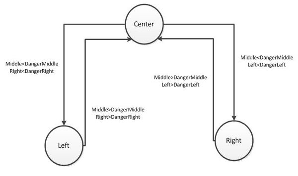
In Movement test task, a state machine is introduced which will enable it to move back and forth, left and right as per the sensor update values. Back Motor will enable the car to move with a particular speed as per the sensor update values in forward direction throughout the time, power supply is on.
The following diagram will give detail about how direction of the front motor of car is controlled in MovementTest Task:
Testing & Technical Challenges
While testing we got various challenges but the major one was getting fluctuating readings from the left, right and middle sensors. Thus, we had to vary our danger limit and also, fix the way we were trigerring the sensors a couple of times. Due to unstability in the values we also switched a couple of sensors. At first we were using PING))) Ultrasonic distance sensor which was successfully interfaced via Timer1 but gave fluctuating values, then we switched to a Light sensor SRF08 which again gave us the same kind of problem. Finally, we successfully interfaced the same SRF02 Ultrasonic sensor for the Middle values too.
Another problem was placing the sensors at such an angle and height so that the car is able to detect the obstacle in left and right such that it gets enough time and correct assumption for turning the other side. This was quite challenging and we had to change the placement of sensors quite a few times by analysing the readings they were giving. Debugging of the values we were getting via the sensors was the most tricky part where it was very important to analyse how the car should behave when it encounters an obstacle. Using test cases and debugging many times we finally got the desired result with a set of danger limit values within which the car needs to change the direction. Creating a state machine first and then implementing it was the idealistic approach for overcoming such kind of challenges.
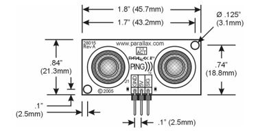
- We used PING))) sensor before in our design but due to some stability problems, our team switched to SRF02 Ultrasonic sensor.
PING))) Ultrasonic Distance Sensor
- Range: 2cm to 3m
- How to trigger PING))) Ultrasonic distance sensor:
- Initialize P0.10 as General Purpose Input Output pin (GPIO). Configure it as output using IODIR0.
- This pin is connected to SIG i.e., I/O pin of PING))) Ultrasonic sensor.
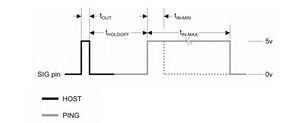
- The signal waveform on SIG is given below:
- At first it is kept high for 20 microseconds by using IOSET.
- After 20 microseconds, the signal is cleared i.e., made LOW by IOCLR.
- SIG is configured as input soon after the signal is low. It needs to receive back the ultrasonic burst that it sent to detect the object.
- After we configure it as input, the I/O pin bits are now set to Capture1.0 (Timer 1) as Timer 0 is already used by FreeRTOS.
- How to calculate the width of the pulse:
- Initialize capture for Timer 1 in order to capture the count of PCLK in its register T1CR0 as soon as it encounters a falling edge i.e., at the end of t(IN_MAX).
- A variable (suppose TriggerTime) is initialized to 0 i.e., at the beginning.
- Now, trigger PING))) sensor while polling.
- The TriggerTime value is updated to the 32-bit value of register T1TC i.e., Timer counter .
- The final value in microseconds would be: (final value in T1CR0)-(TriggerTime).
- Also, the HOLD-OFF time is 750 microseconds which needs to be subtracted from the value for the ultrasonic burst time.
- Converting Width of the pulse into inches:
- The microseconds time is then converted into inches using the following formula:
- 1 inch = 73.76 microseconds
- So, x microseconds = (x/73.76) inches
Conclusion
We were successfully able to customize our self drive car in such a manner that it was detecting any obstacle coming in its way and very intelligently turn in other direction which is safe to move on. The speed control using PWM driver and also, the updating values using the three distance sensors worked in correct fashion. The two tasks synchronized very well in order to make this project a great success. It is not all, we will be improving our design in the upcoming semester for various other features like, responding to hand gestures, honking when finds any obstacle. After accomplishing this task of our project, we learnt a lot of basic and important things about writing drivers from scratch, interfacing any kind of sensor using I2C, external interrupts and Timer. We learnt to design our own machine which will not only works well but is also presented well.
References
Acknowledgement
- Dr. Haluk Özemek
- Preet Kang
- Allen Mamaril
References Used
- SRF02 Ultrasonic sensor Datasheet http://pishrobot.com/files/products/datasheets/srf02.pdf
- PING))) Ultrasonic distance sensor Datasheet http://www.parallax.com/dl/docs/prod/acc/28015-PING-v1.3.pdf
- LPC2148 Microcontroller Datasheet File:CmpE146 S12 T2 LPC2148 Datasheet.pdf
