S15: Connect Four - Robotic Player
Contents
- 1 Grading Criteria
- 2 Konnector (Artificially-Intelligent Connect Four Robot)
- 2.1 Abstract
- 2.2 Objectives & Introduction
- 2.3 Team Members & Responsibilities
- 2.4 Demonstration Video
- 2.5 Schedule
- 2.6 Parts List & Cost
- 2.7 Design & Implementation
- 2.8 Testing & Technical Challenges
- 2.9 Conclusion
- 2.10 References
Grading Criteria
- How well is Software & Hardware Design described?
- How well can this report be used to reproduce this project?
- Code Quality
- Overall Report Quality:
- Software Block Diagrams
- Hardware Block Diagrams
- Schematic Quality
- Quality of technical challenges and solutions adopted.
Konnector (Artificially-Intelligent Connect Four Robot)

Abstract

Play Connect Four against an Artificially Intelligent robot with variable difficulty. Prepare to test your ability to think into the future and your proficiency at connecting your pieces against an ideal player. Connect Four
Objectives & Introduction
The objectives of this project is to implement a robotic connect four player with the same capabilities as a human being with respect to the task of connecting pieces by inserting them into one of seven columns at the top of the board. Just as a human can see where his opponent has played his move and can insert his next move into the board, this robot will implement imitations of these basic human abilities.
Team Members & Responsibilities
   Matthew Carlis   (Jack of all Trades) - Hardware/Mechanical,
                                           Artificial Intelligence,
                                           System Architect,
                                           Technical Writer.

   Alexander Koumis (Image/Driver Guru)  - Drivers,
                                           Image Processing,
                                           Software Interfaces,
                                           Techincal Writer.
Demonstration Video
The following is a link to a video of a student playing the robot on demonstration/presentation day.
- Connect Four Robot with AI beats unsuspecting SJSU student.
- REMIX - Connect Four Robot with AI beats unsuspecting SJSU student.
Schedule
- Semester long project beginning half way through the semester.
| Story# | Points | Task | Description |
|---|---|---|---|
| 1 | 15 | Motor Controller | Write a Stepper motor driver with variable frequency capabilities with constant linear acceleration. This driver should slowly speed up the motor and slowly bring it down while being capable of mapping PWM frequency to pulley frequency. |
| 2 | 10 | Bluetooth Socket. | The micro-controller will be run in combination with a workstation using Bluetooth message passing. The workstation will implement the AI programming where the micro-controller simply tells the workstation through Bluetooth where each move is made by the human and is returned the column number of where to insert the robots next piece. The workstation will implement a Python program interface. |
| 3 | 20 | AI Brain. (It's alive!) | A Python program running on an workstation will implement the "Brain" of the robot where messages are passed between the micro-controller and workstation through Bluetooth. This program will determine where the robot will insert his next move based on which column the human inserts into as reported through the Bluetooth message protocol. |
| 4 | 30 | Mechanical System. | The mechanical system be capable of inserting it's own pieces using linear motion and a stepper motor. The robot will drop his piece into a funnel device which is driven over the column for which the robot wishes to play. After his human opponent has inserted his piece the robots eyes will detect the location of the humans insertion and reply by inserting his next piece. |
| 5 | 25 | The Eyes. | Using the pixy camera to determine the current configuration of the Connect Four board for the robotic player. Using statistical filtering by oversampling the frames the robot will be see each piece as it is inserted. |
| Story# | Points | Story | Burn-down | Time Invested | Actual |
|---|---|---|---|---|---|
| 1 | 15 | Motor Controller | 15 | 15 Hours | 14% |
| 2 | 10 | Bluetooth Socket. | 10 | 3 Hours | 4% |
| 3 | 20 | AI Brain. (It's alive!) | 20 | 18 Hours | 14% |
| 4 | 30 | Mechanical System. | 30 | 30+ Hours | 29% |
| 5 | 25 | The Eyes. | 25 | 40+ Hours | 39% |
| Event# | Date | Task | Actual |
|---|---|---|---|
| 1 | 3/1 | Spec out Design | Completed: Started the system hardware/mechanical specs and materials ordering. Software interfaces are well defined, but not implemented. |
| 2 | 3/18 | Ordered Materials | Completed: Completed mechanical design/research and ordered the majority of the significant materials. (Stepper motor, timing belt/pulleys, liner motion accessories) |
| 3 | 4/1 | Structure Materials | Completed: Received and obtained the majority of the significant materials for the mechanical structure. |
| 4 | 4/20 | Major Milestone | Completed: Bluetooth interface, Stepper Motor Driver, Mechanical specs/ordered, AI implementation. |
| 5 | 4/27 | Projected | ToDo: Finish assembling the mechanical, add linear acceleration to motor driver. |
| 6 | 5/25 | Major Milestone | Pixy Camera integration with the completed mechanical system. Interface a stepper motor, stepper driver, servo, and camera together. |
Parts List & Cost
Give a simple list of the cost of your project broken down by components. Do not write long stories here.

| Qty (Extra) | Description | Manufacturer | Cost |
|---|---|---|---|
| 1 | Stepper Motor Driver 3A | SmartSain | $19.99 |
| 1 | Stepper Motor | Lin Engineering | $45.90 |
| 1 | 24V-40W PSU. | CircuitSpecialists | $14.79 |
| 1 | Pixy Camera CMUcam5 | Pixy | $69.99 |
| 1 | XBee Bluetooth | XBee | $27.95 |
| 2 | Timing Pulley's | N/A | $11.95 (each) |
| 1 | Timing Belt | N/A | $9.95 |
| 4 | Linear Rail Guide | N/A | $3.95 (each) |
| 2 | Linear Bearing w/Platform | N/A | $6.95 (each) |
| 2 | 8mm Linear Motion Rail/Shaft Steel | N/A | $15.25 (each) |
| 1 | Servo: Rotation - 0 to 180 degrees | N/A | $17.35 |
Design & Implementation
System Diagram
The following graphic provides a high-level representation of the system's various software/hardware/human interfaces:

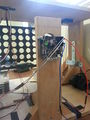
Hardware Design
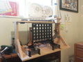
Front Left
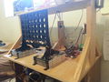
Front Right
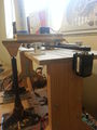
Motor
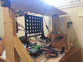
Back Side
PixyCam Back
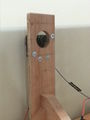
PixyCam Front
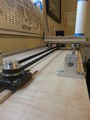
Motion
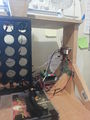
Circuits
Neon-Dot Stickers


Hardware Interface
In this section, you can describe how your hardware communicates, such as which BUSes used. You can discuss your driver implementation here, such that the Software Design section is isolated to talk about high level workings rather than inner working of your project.
- Physical Layer Interfaces
- SPI - Pixy Camera
- Bluetooth - Laptop Communication
- PWM (servo) - 1 PWM signal variable Duty Cycle, static frequency. (24V Motors, 5V Control Signals)
- Stepper Motor Driver - 3A capable with inductive load isolation.
- PWM (stepper) - 1 PWM signal with 2 Control signals. i.e. Step-Enable, Direction-Control, Motor-Enable
- Stepper Motor Driver
- Motor Decay Settings (fast/slow decay) - Stepper motor decay is the rate at which inductive noise is handled after the motor has just turned off or switched direction/loads. The motor draws a reasonable amount of current which results in very powerful inductive affects during signal/motor acceleration. Decay Mode is the setting that allows you to funnel this excess current out of the coil loop more or less quickly which changes the way the motor accelerates. Generally speaking fast decay mode deals with this inductive spike by most quickly draining through protection diodes or more complex mechanisms where slow decay still achieves the same end result at infinity, but takes more time when draining out the inductive current. We chose fast decay to ensure the motor stops as quickly as possible by removing any steps that might be produced from inductive affects.
Software Design
The system's software interfaces are comprised of the following components (organized by their respective hardware hosts):
- Laptop
- SJSU One
The following graphic displays the system's various task state relationships:

Bluetooth Socket Interface
The robot implements a Bluetooth interface between a python program running on an Intel64 Linux machine and the SJSU One robot. This interface is used to send a message from the robot about where the opponent has played his move to the AI on the laptop where the next move calculation is performed. The next move is then returned to the robot over Bluetooth from the Python AI and then the motors are used by the SJSU One to insert the next move into the board and watch for the opponents following move repeating until the game ends. The SJSU one is interfaced using the UART0/printf to send/receive over this Bluetooth channel. The Python Bluetooth socket implements two synchronous user space threaded where a child thread is blocking on receives, waiting for data from the robot’s eyes about where his opponent has played his move. The child thread parses on a regular expression timeout loop implementing a synchronous interface/queue to the brain of the AI which is calculating potential moves. When the AI’s/parent thread synchronizes with the Bluetooth socket’s child thread over a queue the AI calculates for another 5 seconds before returning the next move for the robot which uses motors driven by the SJSU one to insert his move. The child-thread implements a synchronous kill where the block on receive times out every few milliseconds and checks to see if the child-thread should self destruct. When kill is triggered by SIG-INT, the AI or an exception the socket kills the data send/receive, reads all of the data from the buffer, and closes the Bluetooth socket. This ensures the kernel properly re-allocates its resources to the Bluetooth driver allowing clean reconnections.
""" game_socket.py
"""
class GameSocket(threading.Thread):
    def __init__(self):
    def _teardown(self):
    def run(self): # Blocks on receive from the bluetooth.
    def connect(self):
    def _send_data(self): # Asynchronous send.
    def get_move(self): # Synchronizes threads on the queue.
Connect 4 AI
The Connect Four AI was completed using the The MiniMax Algorithm with Alpha/Beta Pruning. MiniMax/Alpha-Beta use a heuristic calculation which essentially comes down to a numerical value which estimates the effectiveness of a particular move or state of the board based on the number of connected pieces. The algorithm works it's way down the game tree evaluating the heuristic value for the leaves of the adversarial search tree in an attempt to maximize the AI's performance by backing these values up the recursion stack and making decisions based on the effectiveness of moves in the distant future. The AI's goal is to find the subtree of the current root which evaluates to the highest performance according to the heuristic.
Our heuristic is extremely simple in that it only looks at the maximum number of connected pieces per player at any given configuration of the board. It also takes into account the fact that some moves cannot be extended further because they may be buried by the opponents pieces or into a wall of the board. If a move cannot be extended further the heuristic ignores these pieces only looking for positions/moves that he can extend. This is no where near a perfect heuristic for Connect Four and it can result in somewhat unpredictable behavior in certain circumstances, but at times the AI performs flawlessly. Coming up with a more effective heuristic is somewhat mathematical process for Connect Four therefore we took the shortest path to designing our AI under the given time constraints.
Alpha/Beta Pruning pruning is a technique which allows the algorithm to dynamically cut subtrees off during evaluation by allowing MiniMax to detect when a certain subtree is worse for him than an already existing option. In other words the Algorithm will try to not expand subtrees which are obviously advantageous to the opponent. This allows the algorithm to go twice as deep into the Adversarial Search Tree where the Time Complexity Before Alpha-Beta pruning of MiniMax is O(b^d) where improved to O(b^(d/2)) using Alpha-Beta pruning. This lets us look twice as far into the future with the same code basically. Memory of MiniMax with/without Alpha-Beta pruning is O(d).
""" four_connect.py
"""
class GameBoard(object):
    def __init__(self, width, height, game_board):
    def __repr__(self):
    def __str__(self):
    def terminal_check(self): # Is the game over? i.e four in a row?
    def insert(self, column, symbol):
    def get_best_heuristic(self, symbol): # Get this symbols best heuristic from this board.

class GameNode(object): # Has a GameBoard()
    def __init__(self, parent=None):
    def get_state(self): # Get the state of the board.
    def get_parent(self): # Get the reference to the parent of this node.

class ConnectFour(object): # Has a GameNode() i.e the current state.
    # Has a GameSocket() to interface with the robot.
    def __init__(self, player_first=False):
    def print_map(self, no_move=False):
    def insert(self, column, player):
    def state_machine(self): # Turn/Taking
    def _next_turn_event(self): # Calls MiniMax() and receives opponents move.
GameTask
The GameTask is essentially the master task for the Connect Four robotic environment. This task is responsible for I/O through bluetooth to the Laptop, dispatching the Stepper Motor to insert pieces into the board, and enabling the Pixy Camera to detect the column of the most recently inserted piece by the opponent. This task can be though of as the dispatcher who watches over subtasks for completion and manages the overall operations of the game. Using FreeRTOS Queues to synchronize each task around an TX/RX queue for scheduling.
MotorTask
- Motor Task - responsible for stepping the stepper motor a certain number of decimal rotations according to what is received by the GameTask in the MotorTask RX Queue. This task sends the platform over the column for which to insert, and then activates a servo motor that drops the chip into the board before stepping back to the home position of the platform (All the way Right). The job of this task is to poll the registers which determine the number of steps that have occurred and correlating this to a number of rotations. Once the process of inserting a piece is completed the MotorTask signals GameTask that it has completed using a FreeRTOS Queue.
- Stepper Motor Control - performed using the MCPWM registers & a single PWM Pin with implementation of variable frequency and hooks for acceleration in the future. This motor controller interfaces the CPU with pins for a Step-Enable, Direction-Control, and Motor-Enable pins from the micro-controller to the stepper motor driver. Our stepper motor driver requires Motor-Enable to be asserted which will then step the motor once per rising edge of the Step-Enable pin according to Direction-Control. In order to accommodate these requirements Step-Enable is driven as a PWM where Direction-Control and Motor-Enable are simply GPIO.
- MCPWM Register - This Motor PWM control register works by using a counter register, and two registers which correspond to the active duty cycle and the total period of the cycle. When the duty cycle register becomes equal to the counter register the PWM is toggled from ACTIVE to INACTIVE (High to Low for us) and when the period length register is equal to the counter register it resets the cycle toggling the PWM to it's active state again. The number of steps can be determined by counting the number of times the counter register is reset to zero which can be accomplished on an interrupt routine or a polling driver. The counter register frequency can be determined based off the the peripheral clock for the registers which in turn corresponds to motor rotation frequency.
- Stepper Motor Stepping Modes - Half Stepping, Full Stepping, Eighth Stepping, Sixteenth Stepping. Most stepper motors are advertised based on their full stepping value i.e. 200 steps per rotation, but a motor can be driven in a number of different ways. Half Stepping would take it up to 200 steps per rotation, eighth stepping up to 1600 steps, and sixteenth stepping up to 3200 steps per rotation. This is accomplished by the way that degrees of polarity is alternated between the coils. Electrically speaking the more steps per rotation, the more analog the signal becomes. This Stepper Motor driver handles the Stepping types using DIP switches so luckily for us we don't have to handle it in software at all.
PixyTask
Drivers for the Pixy were designed using Ozmekian system principles (every machine characteristic/action has a corresponding human analogue). The Pixy's primary tasks as part of Konnector is to send the location and coordinates of human-inserted Connect 4 game chips to the SJSU One board. This involves recording location/coordinate information of incoming blobs, performing statistical analysis on said blobs, and subsequently notifying other system components once a human chip-insertion has been detected. The Pixy's software interface is therefore comprised of the classes PixyBrain, PixyEyes, and PixyMouth, each one encompassing the corresponding facilities that would be required of a human assuming the same role.
Following the same analogy, the 'Pixy' class can be thought of as the system's consciousness/soul, defining actions for each component to take in response to system states. 'PixyTask' then assumes the role of the system's physical body, comprised of all of its individual components, animated by actions invoked by the consciousness during run-time.
The system's states are enumerated as follows: (Github):
enum State_t
{
    CALIB             = 16,
    WAITING_FOR_HUMAN = 17,
    WAITING_FOR_BOT   = 18,
    ERROR             = 19,
    RESET             = 0x01, // SW(1)
    EMA_ALPHA_UP      = 0x02, // SW(2)
    EMA_ALPHA_DOWN    = 0x04, // SW(3)
    SW_4              = 0x08  // SW(4)
} eState, eLastState;
The CALIB state is run at system startup, constructing a 6x7 grid of chip positions to be referenced later in the game (full discussion).
The WAITING_FOR_HUMAN and WAITING_FOR_BOT states encompass the system's behavior when waiting for human chip-insertion, and the AI's next-move instruction, respectively.
RESET, EMA_ALPHA_UP/DOWN and SW_4 are mapped to the SJSU One's push-buttons , respectively, with RESET wiping current calibration settings/game state, and EMA_ALPHA_UP/DOWN allowing run-time adjustment of the tolerance parameter used in the chip-detection algorithm.
Unexpected data values/return codes cause the system to enter the ERROR state, where accumulated error messages are retreived from an error queue.
PixyTask invokes state reactions by calling vAction() within the bool run(void*) function (a task-runner interface):
bool run(void *p)
{
    pPixy->vAction();
    return true;
}
void vAction() is then defined as:
void vAction()
{
    eLastState = eState;
    xFuncMap->vResponse(eState)();
}
xFuncMap is prepopulated with lambda functions in response to every possible State_t key. For example, handlers for WAITING_FOR_HUMAN and WAITING_FOR_BOT are set as follows:
xFuncMap->vSetHandler(WAITING_FOR_HUMAN, [&] ()
{
    // Blocks until N chips are sampled
    pPixyBrain->lSampleChips(pPixyEyes.get());
    eState = WAITING_FOR_BOT;
});

xFuncMap->vSetHandler(WAITING_FOR_BOT, [&] ()
{
    PixyCmd_t xBotInsertCmd;
    // Blocks until command received over shared queue
    if (xQueueReceive(getSharedObject(shared_PixyQueue), &xBotInsertCmd))
    {
        PixyBrain->lBotInsert(xBotInsertCmd);
        eState = WAITING_FOR_HUMAN;
    }
});
These reactive symantics are made possible by the templated 'FuncMap_t' utility struct, allowing function pointers (std::function) to be stored in a map, invoked later in response to key values of arbitrary type:
template<typename KEY_T, typename FUN_T, typename ... ARG_T>
struct FuncMap_t
{
    /* The core std::map object, mapping KEY_T's to std::function's */
    map<KEY_T, function<FUN_T(ARG_T ... xArgs)>> fpMap;

    /* Method used to insert (KEY_T, std::function) key/value pairs */
    void vSetHandler(KEY_T xElem, function<FUN_T(ARG_T ... xArgs)> fnHandler)
    {
        fpMap[xElem] = fnHandler;
    }

    /* Method called during run-time to invoke stored lambda function */
    function<FUN_T(ARG_T ... xArgs)>& vResponse(KEY_T xElem)
    {
        return fpMap[xElem];
    }
};
PixyBrain
Effort is taken to compartmentalize computational duties solely to PixyBrain. #PixyEyes performs no role other than to record seen blocks over a certain time period, providing this information to PixyBrain when queried. PixyBrain uses this information, along with prior knowledge of current game state, to determine when the human opponent has inserted a new chip. PixyBrain then delegates #PixyMouth to forward this information to the Python AI, sending the (int) column value over a shared FreeRTOS queue.
Corner calibration
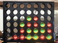
The first action executed by the system is to determine pixel coordinates (x, y) of each of the board's four corner chip slots. A predefined number of blocks are sampled from the stream sent from #PixyEyes , each one adding to one of four running averages depending on the quadrant they fall in. Assuming only the top left, top right, bottom left, and bottom right slots are occupied by the set calibration chip color, the final average coordinates are used to construct the full grid of slot locations.
Insertion detection
The smallest distance between all possible next chip positions (whose coordinates are determined during camera calibration ) and incoming blocks from PixyEyes is calculated for block. An exponential moving average is kept for the likelihood of each chip's being one of the three possible colors, NONE, GREEN, or RED. Once the system has reached a certain level of confidence that the chip is a certain (none-NONE) color, the column number is sent through #PixyMouth to notify the AI of the location of the chip.
PixyEyes
Determining the location of chips with PixyEyes involves sampling data incoming over SPI. Example code [was provided] for this purpose but, unfortunately, did not function correctly under FreeRTOS' tight memory constraints. Alternative drivers were written, attempting to conform to the [defined protocol], where data is sent in 14-byte blocks as follows:
Bytes    16-bit word    Description
----------------------------------------------------------------
0, 1     y              sync: 0xaa55=normal object, 0xaa56=color code object
2, 3     y              checksum (sum of all 16-bit words 2-6)
4, 5     y              signature number
6, 7     y              x center of object
8, 9     y              y center of object
10, 11   y              width of object
12, 13   y              height of object
After the block is populated, it is added to a static-sized std::vector<PixyBlock>, used later by PixyBrain to determine chip location.
PixyMouth
PixyMouth is invoked by #PixyBrain to send the column of human chip-insertion over a FreeRTOS queue , which unblocks #GameTask to send the command to the AI module listening on the Bluetooth socket.
Implementation
This section includes implementation, but again, not the details, just the high level. For example, you can list the steps it takes to communicate over a sensor, or the steps needed to write a page of memory onto SPI Flash. You can include sub-sections for each of your component implementation.

Testing & Technical Challenges
Testing was difficult because it required the entire mechanical system before many of the features of the system could be implemented so the greatest prerequisite to the project was simply bolting all the parts together. Once this was completed the camera and mechanical were developed/tuned in parallel and eventually merged into a complete device. Spend more time on research and less time banging the keys to ensure time isn't wasted on bad assumptions about register configurations or device operation. Develop in person with others once the system is merged and help to bridge the gap between your code and your partners code in person to solve problems faster. Talk about issues out loud with your group members and restate assumptions before proceeding to find a solution.
My Issues
- You cant use Software PWM's to control a Stepper Motor - I tried to implement a stepper motor driver using GPIO pins and if conditions which determined at what point to change the active state. A stepper motor must be driven very smoothly where there is very little deviation between pulses and cycles. When using a software PWM the motor would become stuck and not rotate at all, but after switching to MCPWM which is a true hardware PWM the motor behaved extremely accurately/precisely. So if you're using a Stepper Motor use some kind of circuitry which produces very symmetrical cycles so the motor doesn't get stuck.
- You Cant Service I/O on I2C/UART/SPI if your task is set to HIGH Priority and spinning all the time - Task Priority was set to high on the Pixy/Camera task and was causing SPI/UART to not work properly. This was fixed by reducing the priority from HIGH (Which was an obvious mistake) to LOW which is much more appropriate since the task does not require any instantaneous operation or scheduling.
- Don't expect 3rd party code/drivers to be any good - Using code provided from the developers of the Pixy Camera we we're unable to properly parse the data from the SPI off of the camera. We tried to use their code at first, but it had very bad CRAP (CHANGE RISK ANTI-PATTERNS & CODE COMPLEXITY, it wasn't easy code to read or figure out how it behaves) due the way it was designed so we we're forced to come up with our own driver which fixed the issue with parsing the data from the Pixy.
- Using a Camera to detect patterns/colors and map to row/columns is very hard. - There is lots of noise in the data, extreme variations due to lighting changes, and objects in the environment which could confuse the algorithm. We we're able to model the problem statistically by using a training session which requires a chip in each corner of the board to build a statistical estimate of where each row/column resides in relation to pixels from the resolution of the camera. A solid/simple technique must be used when adopting cameras into projects and running/exponential averaging/variance must be utilized in a way that is consistent with assumptions made about incoming data. You will need statistics if you wan't any meaningful results from image detection so get ready to find better/faster algorithms to record data.
Conclusion
Since the scope of this project spanned embedded systems, simple adversarial game algorithms, and python programs running user space threads we learned a lot about leveraging different technologies at different complexities and combining them into a single coherent project. Synchronization between different programs in different machines around a bluetooth channel will allow our designs to be more computationally flexible in the future especially in combination with the gained knowledge of image processing, and stepper motor control. We learned a lot being able to dive into the lowest level registers in the LPC1758 as well as the high level of abstraction provided by Python.
Project Video
The following is a link to a video of a student playing the robot on demonstration/presentation day.
- Connect Four Robot with AI beats unsuspecting SJSU student.
- REMIX - Connect Four Robot with AI beats unsuspecting SJSU student.
Project Source Code
- Sourceforge Source Code Link (Project Baseline)
- Connect Four:
- release - Final implementation of combined features.
- Feature Branches: Only maintained pre-merge/rebase with release branch.
References
Acknowledgement
We changed our lifestyles. - Dr. Ozemek.
References Used
Nothing you can't find using google on generic websites about motors, drivers, circuits, software, python, C++/C, etc. We googled our way through this project, but don't expect to be able to rely on internet designs exactly as they are. Reading the datasheet of the LPC1759 and understanding the principles of embedded systems is the necessary foundation/prerequisite.
- Topics:
- Stepper Motor Decay
- Stepper Motor Stepping (full stepping / half stepping / eighth stepping etc)
- Driving a Stepper Motor
- MiniMax/Alpha-Beta Pruning/Heuristics (AI Algorithm)
- Python bluetooth/sockets/threads/queues
- Circuits (duh! This is CMPE after all)
- Math (The kind a calculator can't do for you.)
- Color Detection Techniques and the best colors/lighting.
Appendix
See References Used.