S15: Quadcopter - It flies
Contents
SpartansQUAD
Abstract
As efforts to make the world a safer place, advancements in unmanned aerial vehicles (UAV) technology have skyrocketed. It is now possible for soldiers to remain out of the war zone and still be effective. The concept of UAVs has now ventured from the military platform to one that can be utilized by civilians. Drone technologies are currently under development which will enable law enforcement agencies to monitor public areas without having to put any actual officer lives at danger. Furthermore, drones are the assistant to the workhorse of the future. Not only will drone be used for surveillance in the future, they will be used more extensively in other fields such as film production. Drones will be the cameramen of the future. Their capabilities of being able to move in the third axis will enable drones to aid disaster search and rescue operations.
This report documents the build process of our quadcopter aptly named The SpartansQUAD. The build process, from the software development to the physical building of the quadcopter frame will be discussed in detail. The purpose of this report is to give any reader a very detailed understanding of our concepts and vision for this project.
Objectives & Introduction
The objective of The SpartansQUAD is to interface various components with SJSU’s College of Engineering SJ One Board and use it as a flight controller to sustain stable hovering. The quadcopter is to be controlled via a 6-channel transmitter and receiver combination which will also be interfaced with the SJ One Board.
Team Members & Responsibilities
- Jashan Singh - Lead Engineer
- Onyema Ude - Lead Engineer
Schedule
| Week# | Start Date | End Date | Task | Current Status | Things hindering progress |
|---|---|---|---|---|---|
| 1 | 4/14 | 4/28 | Ordering Parts/(Re)Assembling Frame | Essential parts received; frame built with motors attached; misc. items to be ordered throughout project | N/A |
| 2 | 4/14 | 4/19 | IMU SJOne Board Interfacing | Complete | Lack of familiarity with breakout board and unable to get training |
| 3 | 4/21 | - | Decoding RC Signals for SJOne Board Interfacing | Complete - (Throttle values obtained (code already finished by other group?); Testing motor output from RC input) | Remote control mode configuration |
| 4 | 5/5 | 5/7 | Coding SJOne Board for parsed IMU data (post-assembly) | Complete | - |
| 5 | 5/12 | 5/01 | Pairing IMU and RC input to output to the motors | Complete | - |
| 6 | 4/14 | 5/24 | Fine tuning and testing | Test rig built. Debugging issues. | Smooth collaborative flight across pitch and roll axis |
Parts List & Cost
| Qty (Extra) | Description | Manufacturer | Cost |
|---|---|---|---|
| 4(2) | Afro ESC 30 Amp Speed Controller (SimonK Firmware) | Turnigy | $84.00 |
| 2 | Motors & Propellers Combo | T-Motor | $180.00 |
| 1 | Turnigy 9X 9Ch Transmitter w/ Module & 8ch Receiver (Mode 2) (v2 Firmware) | Turnigy | $59.99 |
| 1 | Turnigy nano-tech 4000mAh 3S1P 25-50C Lipo Pack | Turnigy | $26.90 |
| 1 | Turnigy Talon Quadcopter (V2.0) Carbon Fiber Frame 550mm [1] | Hobbyking | $54.49 |
| 1 | Hobbyking Quadcopter Power Distribution Board | Hobbyking | $3.39 |
| 1 | Hobbyking Lipoly Low Voltage Alarm | Hobbyking | $2.15 |
| 1 | Turnigy Battery Strap | Hobbyking | $1.59 |
| 1 | Mounting Pad | Hobbyking | $1.99 |
| 1 | 3.5mm Bullet Heads | Polymax | $1.83 |
| 1 | Turnigy 3000mAh 3S1P 30C Lipo Pack | Turnigy | $21.98 |
| 1 | iMax B6 Battery Charger | IMAX | $33.46 |
| 1 | Hobbyking 2.4Ghz 6ch Tx USB cable | Hobbyking | $2.99 |
| 1 | Arduino Wireless Bluetooth Transceiver Module Slave 4Pin Serial + DuPont Cable | KEDSUM | $9.99 |
| 1 | FlySky FS-T6 2.4ghz Digital Proportional 6 Channel Transmitter and Receiver System | FlySky | $57.99 |
| Total: $532.75 |
Design & Implementation
The various designs incorporated in makings of the SpartansQUAD vehicle were implemented with cost, efficiency, and sustainability in mind so that it would be easy to replicate or improve various aspects of the system.
Hardware Design
The hardware design of the quadcopter was based on the "plus" (+) configuration. That is, one motor would be assigned a direction based on the two dimensional plane -east, west, north and south.
Hardware Interface
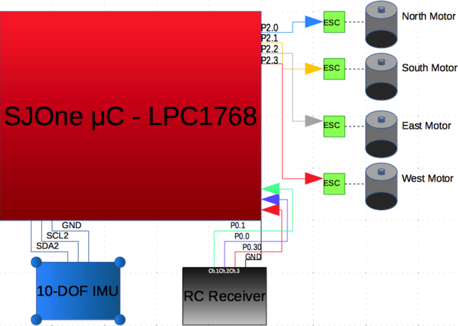
The speed of the motors is determined by a PWM (Pulse Width Modulation) signal to the ESCs (Electronic Speed Controllers). A PWM signal is a digital signal which is usually implemented to obtain the effects of a analog signal. It works by altering the width of a square wave (pulse) and the amount of time it is at a logical 1 and logical 0. The altering of the logic zero and one many times during one time frame (or period) determine the duty cycle, the percentage of time the signal is a logical 1 during one period. The ESCs used on the SpartansQUAD were given the initialization PWM signal of 500 hertz (Hz) and were given a duty cycle between 10 and 95 percent: i.e 10 percent equaling 0 throttle and 95 percent equalling full throttle. On the SJOne microcontroller board, GPIO pins P2.0, P2.1, P2.2, P2.3, with PWM capabilities, were each attached to the north, south, east, and west ESCs respectively.
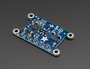
To obtain orientation values of the quadcopter, the Adafruit 10 DOF IMU (inertial measurement unit) was utilized. The sensor was data was transmitted to the SJOne board via the I2C(2) bus. This allowed for the logging and calculating of the gyroscope, magnometer and compass values to the SjOne board at the rate of 500 hz. The software used these three values in tandem to calculate the orientation of the quadcopter and based on the orientation, the software sent out proper values to the motors to counter any change in orientation.
Microcontroller
The SJOne microcontroller was used as the main controller for the quadcopter. The SJOne microcontroller is a very versatile controller and served as an excellent platform as the brains of this project. It contains a LPC1758 microchip which, with the help of auxiliary components, processed the incoming IMU sensor data and the remote control data.
Frame
We chose the Turnigy Talon carbon fiber frame as the chassis for the project. We decided on a carbon fiber frame for it's light weight, and structural rigidity. It served as a very robust and very customizable frame for our purposes.
Remote Controller and Receiver
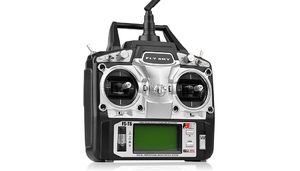
The user input data was sent by the Fly Sky FS-T6 remote control and receiver. The following channels were utilized on the six channel receiver for this project:
Inertial Measurement Unit - L3GD20H + LSM303 + BMP180
The IMU or inertial measurement unit used for this project was an integral component. The IMU serves as the sensory component of the quadcopter by relaying information about its orientation in relation to the earth's magnetic and gravitational fields. This particular IMU contains the L3DG20H gyroscope, LSM303DLHC accelerometer compass and the BMP180 barometric/temperature sensors. The sensor values are sent to the microcontroller over a I2C bus. The values are then used for angle computations as well as finding the change in the system via the PID algorithms. For our purposes, the gyroscope and accelerometer sensors were used for basic flight. In the future, the barometric pressure sensor can be implemented to aid with autonomous flight.
Software Design
The software needed to make this project possible required a robust programming language. The entire software is structured by using object oriented programming techniques in C++. C++ allows for a very reliable communication between the software and hardware of the entire system.
Our project was made possible with the use of FreeRTOS (Free Real Time Operating System) to run the various tasks in a priority based hierarchy.FreeRTOS utilizes an interrupt based system where a higher priority task can interrupt a lower priority task to provide real time operation of the quadcopter hardware and software.
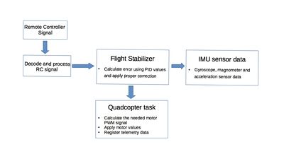
In our software, the "Quadcopter_task" task was given the highest priority to run. This is due to the fact that this task encompasses all the main processes needed for basic flight. This task processes the raw sensor data values from the IMU (inertial measurement unit) sensor which are fed to various filters and then applied to the flight controller inputs to fly the quadcopter.
At the heart of our software was the PID controller. In essence, a Proportional Integral Derivative controller is a software feedback loop which calculates an error value. This error value is used to compare to the desired set point value. This value of this set point changes according to input by the user and the calculated input by the IMU sensor. This comparison is used by the PID controller to determine the required changes needed to bring the system to the set point, essentially attempting to keep the system at homeostasis.
Testing & Technical Challenges
The main challenges that arose from the creation of The SpartansQUAD mostly dealt with low level understanding of the system. For instance, understanding the workings of PID control systems before testing would have helped a lot. Since quadcopters solely rely on this concept, it is critical to have a full understanding of the parameters that are involved. In our case, testing was done with a high level understanding of the concept, so there was some uncertainties during testing. Being comfortable with the parameters, units, and even theory of PID control while transitioning into the testing phase of the project will definitely increase productivity and control of the system.
We built a wooden testing rig to test and tune the PID values. The testing phase was the most tedious aspect of the entire project as the quadcopter reacted very sensitively to the slightest change in the PID values. Consequently, testing involved changing the PID values by very small increments, removing the quadcopter from the test rig and testing the quadcopter's free flight. This process was repeating several tens of times as the quadcopter behaved incredibly differently than the expected behavior as seen while on the test rig. Unfortunately, despite the enormous time spent on testing and tuning, we were unsuccessful in getting stable flight from the quadcopter.
Challenges
| # | Technical Issues | Adopted Solutions |
|---|---|---|
| 1 | Unorganized peripheral layout that resulted in wiring and weight distribution problems | Redesigned a more centralized setup with secure wire connections |
| 2 | Sporadic transmitter values being sent to receiver module | Replaced part with a transmitter that had single channel control |
| 3 | Finding suitable testing rig for single axis tuning | Designed and built an uncommon testing rig that was more efficient than most |
| 4 | Sporadic IMU sensor readings due to external vibrations | Implemented rubber stoppers to base of IMU sensor for anti-vibration and shock absorption |
| 5 | Simultaneously testing pitch and roll without undesired reactions | Unresolved |
Conclusion
Overall, we tried to keep minimalist tenor throughout this project so it would be easier to fix or build upon existing system modules. Mechanical and electrical modules; for instance, played a huge role within the construction of The SpartansQUAD, and issues that arose within each module remained separate which made them easier to handle. The best way to describe the development process of this project would be to use the waterfall model, since each stage depends on the completion of previous tasks. It is important to note that having a detailed schedule and allotting specific time blocks throughout the week are two phases of planning that will ultimately contribute directly to the success, or failure, of the project development process. We learned that planning plays a larger role than most may think, so it is critical that each team member hold one another accountable for different parts of the project and deadlines are met or eventually accounted for when issues arise.
It must be noted that although the quadcopter did fly, we were unable to attain stable flight as expected. We are currently running into issues involving the unforeseen motor speeds which are not allowing stable flight. We are in the process of debugging these issues.
As a whole, execution of this project increased our knowledge of each of the following:
- PID control theory
- Project management
- Time/priority management
- Quadcopter rotorcrafts/vertical take-off and landing vehicles (VTOL)
- RC Signal Processing
- Sensor interfacing
- Control system configuration
Project Video
Project video: https://www.youtube.com/watch?v=cLNOYduoB0o
Project Source Code
Project Pictures
- This is a link to an Imgur album containing the build process of the quadcopter: [2]


