S15: Tree Node using Google Protocol Buffers
Contents
- 1 Tree Node: using Google Protocol Buffers
- 2 Problem Statement
- 3 Our Solution
- 4 Abstract
- 5 Objectives & Introduction
- 6 Project Schedule
- 7 Parts List & Cost
- 8 Protocol Buffers
- 9 Nordic Wireless
- 10 Tree Node Architecture
- 11 Hardware Design
- 12 Hardware Interface
- 13 Software Design
- 14 Design & Implementation
- 15 Testing & Technical Challenges
- 16 Conclusion
- 17 References
Tree Node: using Google Protocol Buffers
Problem Statement
With the race to harness the value of big data in full swing, no one is happy about storing multiple versions of data. Its expensive, delays data availability, and just seems like a waste of time. Machines cannot afford to send and receive large chunk of data among each other. Sending large amount of data usually increases the transmission delays in the communication system and as a result the processing time of over all system increases. So, there is a burning need of faster, lighter and smarter way to process and transmit the data in the world of internet of things.
Basic Questions Asked:
- What kind of protocol to use to transmit serial data ?
- What is an efficient method for storing and exchanging the data?
Our Solution
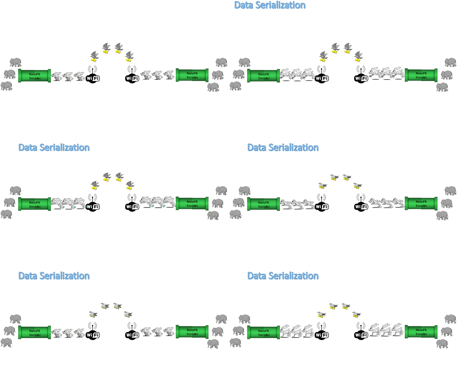
Data Serialization
Historically, handling huge data has been a challenge for developers, mostly due to dependencies across multiple platforms and data access layers. Developers face situations where we want to deploy new code, but some other client relies on the old code. It can stop a deployment dead in its tracks. As models and needs mature more towards data as a service, developers expect that multiple clients would run different versions of a software platforms and even use different languages. In these cases, data serialization become quite important and serves as the best possible option.
So basically, serialization is used when large amounts of data have to be stored in flat files and retrieved at a later stage or to transport over the network. To achieve big data handling without serialization, it becomes too tedious, error-prone and complicated as the data structure is complex. So, we needed a serialization technique that is fast, compact format, easy to define, extensible and platform independent. That's where Google Protocol Buffers come into picture.
Google protocol buffers (GPB) is the best available way for data serialization between servers. By implementing lighter and micro controller compatible version of GPB - nanoPB - we created a faster and better machine to machine communication network. Google Protocol buffers provides neutral and efficient way of serializing structured data for the use in communication protocols.
Abstract
This project is to implement google protocol buffers for serialization of the data. In this main role of protocol buffers is to encode the data before sending it out via nordic wireless communication and decoding the received data on the receiver side.
- This project mainly focuses on Following topics:
- Studying different types of Protocol Buffers (GPB)
      Google Protocol Buffers
      NanoPB
      Protobuf-c
      Flat Buffers
- Implementing Nordic wireless communication between different boards by using these implemented google protocol buffers.
- Studying network architecture - Tree Achitecture
Objectives & Introduction
Show list of your objectives. This section includes the high level details of your project. You can write about the various sensors or peripherals you used to get your project completed.
Team Members & Responsibilities
- Aditya Bankar - Wireless implementation, study of Google Protocol Buffer and FlatBuffers
- Aniruddha Kawade - Nanopb implementation and Documentation
- Shreeram Gopalakrishnan - Nanopb implementation and Documentation
- Vinod Pangul - Wireless implementation, study of Google Protocol Buffer and FlatBuffers
Project Schedule
Following table gives the complete description of in-advance planning and deliverable for the project. This project schedule help us in scoping out the project and keep oneself in check with the progress.
| Week No. | Start Date | Planned End Date | Task | Status | Actual End Date |
|---|---|---|---|---|---|
| 1 | 03/31/2015 | 04/07/2015 |
* Decision on all required modules and placing the order online. * Research on Google Protocol Buffers |
|
04/07/2015 |
| 2 | 04/06/2015 | 04/13/2015 |
* Environment setup of Google Protocol Buffer on windows and accomplish an example task such as hello world. |
we are able to compile the basic program successfully.(AI: to figure out run part of the compiled code).
|
04/29/2015 |
| 3 | 04/13/2015 | 04/20/2015 |
* Nordic Wireless: Ping Test between two SJOne boards. |
|
04/29/2015 |
| 4 | 04/20/2015 | 04/27/2015 |
* Nordic wireless all development and testing for 2-3 SJOne Boards. * Successful implementation of nanoPB ( GPB variant) |
|
04/30/2015 |
| 5 | 04/27/2015 | 05/04/2015 |
* Start code development for LCD module. * Testing Code via Google Protocol Buffers. |
|
05/11/2015 |
| 6 | 05/04/2015 | 05/11/2015 |
* Integration of all modules with parallel testing. |
|
05/20/2015 |
| 7 | 05/11/2015 | 05/18/2015 |
* Integration of the code with Google Protocol Buffers. |
|
05/20/2015 |
| 8 | 05/18/2015 | 05/25/2015 |
* Final Testing and integration of additional features if time permits. |
|
05/25/2015 |
| 9 | 05/25/2015 | 05/25/2015 |
* Final Demo Day |
|
05/25/2015 |
Parts List & Cost
Following are the components and modules required for this project.
Parts List & Cost
| Item# | Part Desciption | Vendor | Part Number | Qty | Cost |
|---|---|---|---|---|---|
| 1 | SJOne Board | SCU Room | Revision 2 | 3 | $240 |
| 2 | Antenna's | SCU room | CMPE 295 | 3 | $12 |
| 3 | Total | NA | NA | $252 |
Protocol Buffers
In the below sections we discuss the different types of Protocol Buffers we explored and how we concluded that Nanopb was suitable for our project.
Google Protocol Buffers
Protocol Buffers was developed by Google for serializing data.
So, what is Serialization? According to Wikipedia, "serialization is the process of translating data structures or object state into a format that can be stored (for example, in a file or memory buffer, or transmitted across a network connection link) and reconstructed later in the same or another computer environment". Google Protocol Buffers is one of the methods used for serializing. The other famous method is XML. But, the main advantage of using Google Protocol Buffer over XML is that it is light weight, which makes it fast. It also has an easier implementation.
Currently, GPB has extended support for many programming languages, but C++, Java and Python are widely used.
Getting Started
The first step for us was to install the package available in https://github.com/google/protobuf/ and follow the instructions given in it. We first tried it in Windows Operating System. Because we were not able to successfully install in Windows, we moved to Linux.
Installation in Windows(Unix terminal)
The SJSU development package consists of a folder MSYS inside MINGW. The proto compiler is the most important thing and it was downloaded from https://developers.google.com/protocol-buffers/docs/downloads. It isused to compile .proto files which produces pb.h and pb.cc files. The protoc binary executable file was then placed inside the bin folder and its path defined in the environment variables. Msys is a unix like terminal used for configuring and building of applications which depend on Unix tools. The below steps for installing GPB were followed -
- Double click on ./autogen.sh. It will run in command prompt. This will generate a gtest folder. It consists of configure files, source code and libraries.
- Now in another window, open msys.bat file to start the unix like terminal.
- Navigate to the gtest folder and run ./configure
- This takes time and checks for gcc compatibility. Also, make sure that your antivirus is temporarily off. If not, the configure file may not be executed successfully and it will give errors like gcc configured
- Once configure runs successfully, type 'make' and execute it.
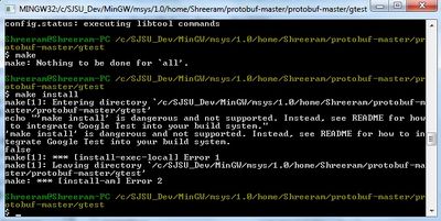
- After executing make, type 'make install' and execute it. Here is where, we faced issues.
After posting on various google groups, we found out that, support has not yet been released for installing GPB with MinGW in Windows. Although, in Windows Visual Studio could have been used, we tried to use eclipse plugins to compile and run.
The plugin to download was available in https://code.google.com/p/protobuf-dt/wiki/Installing. The steps required to follow in eclipse are -
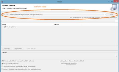
- Xtext and protobuf-dt is installed from http://download.eclipse.org/modeling/tmf/xtext/updates/composite/releases/. This is a descriptor i.e. highlights the keywords. To install the given link in Eclipse -
- Inside the Eclipse CDT, click on 'Help' -> 'Install New Software'. A new dialog box opens where you will have to copy paste the link and click on 'Add'. The software finds the required plugins and you can complete the installation.
- This can be similarly done for 'protobuf-dt' plugin.
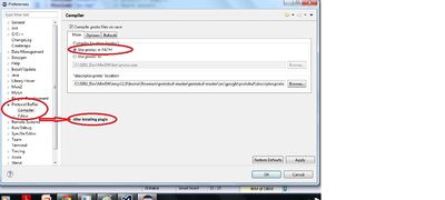
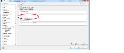
- After installing the plugin, we check if the option 'Protocol Buffers' is present in Windows -> Preferences. As seen in the below figure, we will use protoc in PATH variable and descriptor.proto location is given. Under the Options tab , Gen-C++ is checked so that after compiling, C++ src-gen (Source) is generated.
Installation in Linux
Installing GPB in Linux is simple. Follow the methods similar to Windows Installation in Unix terminal and use it in Terminal in Linux. The installation will be successful because all make files are supported for linux.
Defining a sample proto file
Below is the definition of the proto file and it is saved with a .proto extension. All the proto files are defined through keyword message. The keyword required is a modifier. Other modifiers are optional and repeated. When required is defined, then that particular variable has to be initialized in the main or as mentioned in the below code with default value. For example the below code is defined as hello.proto
Sample Schema
    message hello
    {
        required string text= 1 [default="Hello World!"];
    }
Compiling the proto file and defining source code
Once the proto file is defined, it is then compiled in the terminal. The command protoc --cpp_out = hello.proto will compile the file and generate .pb.cc and .pb.h files. These files contain the API's for encoding and decoding the file. Once these are generated, a source file is created called hello.cpp. The following sample code shows its demonstration.
    int main()
    {
        hello demo;                 // instance "demo" of the "hello" class defined in proto

        const std::string& test = demo.data();    // data is the field where the text was stored
        cout << test << "\n";

        demo.set_data("How do you do?");    // changing the data
        cout << demo.data() << "\n";
        return 0;
    }
Building in Eclipse
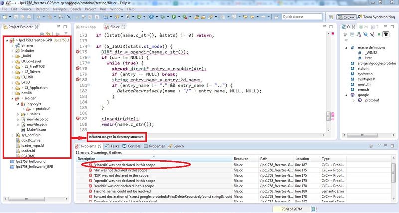
In Eclipse once, we define the proto file we can build it, since we have defined the path for protoc compiler and installed the protobuf plugin. This generates a src-gen folder which consists of hello.pb.h and hello.pb.cc files. Further issues were faced when we tried to integrate it with Preet's folder structure. That will be discussed in Testing and Technical challenges section.
FlatBuffers
FlatBuffers is again cross platform serialization library developed at Google. It is available as open source and is more effective in game development and performance-critical performances.
Source code: https://github.com/google/flatbuffers
Website Link: https://google.github.io/flatbuffers/md__building.html
Why not use Protocol Buffers, or .. ?
Protocol Buffers is indeed relatively similar to FlatBuffers, with the primary difference being that FlatBuffers does not need a parsing/ unpacking step to a secondary representation before you can access data, often coupled with per-object memory allocation.
Usage:
1. Write a schema file that allows the data structures which you may want to serialize.
2. Flatc compiler generates C++ header file.
3. Store or send your buffer somewhere!
4. When reading it back, you can obtain the pointer to the root object from the binary buffer.
NanoPB
Although Google has provided an official protobuffer implementation for C/C++, we were unable to utilize the official version as the embedded system's C library is not fully POSIX compliant, preventing the official implementation from cross-compiling. Protobuffer is also not memory efficient, limiting its implementation on memory constrained embedded systems.
So we turned to nanopb. It is a variant of protocol buffers, specifically designed for embedded systems. Unlike google protocol buffers which generate C/C++ typedef structures, nanopb generates associated C structures which has tiny footprint. Nanopb comes with minimal requirements for RAM and code space and it is primarily suited for 32-bit microcontrollers like ours.
Features
- No requirement for dynamic memory allocations.
- Pure C runtime.
- Memory efficient: small RAM and code size
- Backward compatible.
- Callback mechanism for handling messages larger than can fit in available RAM.
- Most of the protobuffer features by sacrificing some speed.
Structure
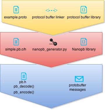
Protobuffer compiler compiles .proto file by linking them to the library functions.
Protobuffer compiler compiles .proto file to .pb file which is not human readable. This architecture is built over the nanopb generator. nanopb_generator.py is python tool script which call upon a number of nanopb library functions and any other user defined application or library functions to generate protobuffer header and source files (.pb.h and .pb.c). Both of these runtime generated files purely consists of C library functions, that’s why low RAM and code space usage.
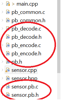
For the runtime program, you always need pb.h for type declarations. Depending on whether you want to encode, decode, or both, you also need pb_encode.h/c or pb_decode.h/c. Application must declare pb.h, encoding/decoding/both header files and pb.h generated by nanopb_generator tool script at the runtime.
Application layer is composed of main function along with nanopb header files and protocol buffer messages.
Installation
Linux
Nanopb is primarily made for linux flavored environments. So a lot of support and literature is available for linux environment. Linux scripts made available with the nanopb installation files and out of the box python support make it very easy to compile and generate protobuffer files. So I would not like to go into these details but they can be found here [1]
Windows
As said earlier nanopb is primarily buil for linux environment, so windows installation is bit complicated and is built over the linux environment. Main issue with the lack of out of the support for python in windows environment. So combination of Dynamic-link library (DLL) files and executables need to be handled during installation.
Steps to be followed:
- Download nanopb-0.x.x-windows-x86.zip (our version is 0.3.3) from [2]. Extract downloaded zip into a folder.
- Install python 2.7 (must use version 2.7 version and not 3.4) from [3] and python protobuf from [4]
- Now go to extracted folder -> generator-bin. Copy python27.dll from python in the nanopb folder -> generator-bin. Make sure you have python27.dll at this location, if not copy it from C:/Windows/System32
- Copy pb.h, pb_common.c/h, pb_encode.c/h and pb_decode.c/h in the current directory.
- Use this as working directory to generate protobuffer source and header files along with file_name.options file in which you can define micro controller related constraints if not done earlier in the .proto file.
Eclipse environment setup
- Though this step is optional but highly recommended. It will simply ignore the protobuffer files if included unknowingly in the working directory. Eclipse has protobuffer plugin for which you will need egit plugin. Go to eclipse -> Help -> Eclipse Marketplace and search for egit and cdt-protobuf.
- Copy pb.h, pb_common.c/h, pb_encode.c/h and pb_decode.c/h in the Eclipse working directory.
Nordic Wireless
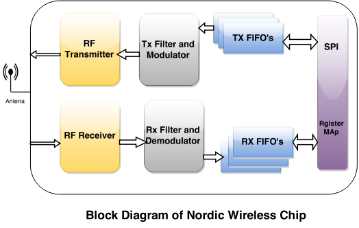
For the wireless communication between two or more SJone controllers, we have used the Nordic wireless communication. SJone board itself have onboard Nordic wireless chip nrf24L01 configured with Serial Peripheral Interface(SPI) which also features Enhanced ShockBurst™. This helps in automatic packet handling and timing. During transmit, ShockBurst™ assembles the packet and clocks the bits in the data packet for transmission. During receive, ShockBurst™ constantly searches for a valid address in the demodulated signal.
The nrf24L01 + Full three level FIFO for both TX and RX direction helps in achieving maximum 0-10Mbps with 4 wire SPI interface. The following Diagram shows internal working of nordic wireless.
Tree Node Architecture
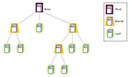
A tree topology includes multiple star topologies, which involve a variety of single nodes connected to a central node. Multiple stars involve either a series or tertiary nodes attached to two or more secondary nodes, which are attached to the tree's primary trunk node.
Experts may define a tree topology as a combination of star and bus topologies, where multiple elements are connected through a single lateral connection.
Each node in a hierarchy level has point-to-point links with each adjacent node on its below level. All secondary nodes have point-to-point attachments to the tertiary nodes in their jurisdiction, and the primary node has a point-to-point connection to each secondary node. When viewed in a visual way, these systems appear similar to a tree structure.
A drawback of a tree topology is that an entire system can be crippled by any damage or malfunction of the primary node. This is why managers of tree topologies often have a "protect the tree" approach, where the primary node receives special attention or safeguards.
Features of Tree Topology
- Ideal if workstations are located in groups.
- Used in Wide Area Network.
Advantages of Tree Topology
- Extension of bus and star topologies.
- Expansion of nodes is possible and easy.
- Easily managed and maintained.
- Error detection is easily done.
Hardware Design
1. Light Sensor:We used TEMT6000X01 light sensor by Vishay Semiconductors. This light sensor is already mounted on SJ One board. TEMT6000X01 ambient light sensor is low power sensor. It is sensitive to visible light much like the human eye and has peak sensitivity at 570 nm. TEMT6000X01 has analog output and is packaged in a small surface mount package. On SJ one board, the ambient light sensor is internally connected using I2C bus protocol.
2. Temperature sensor:
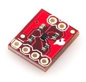
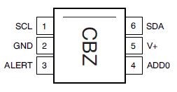
This is a breakout board for the incredibly small TMP102 digital temperature sensor. The TMP102 is a digital sensor (I2C a.k.a. TWI), has a resolution of 0.0625°C, and is accurate up to 0.5°C. The sensor requires very low-current, and is loaded with features.
Communication with the TMP102 is achieved through a two-wire serial interface. There is no on-board voltage regulator, so supplied voltage should be between 1.4 to 3.6VDC. Filtering capacitors and pull-up resistors are included. The fig.4 shows the pin configuration of temperature sensor.
Hardware Interface
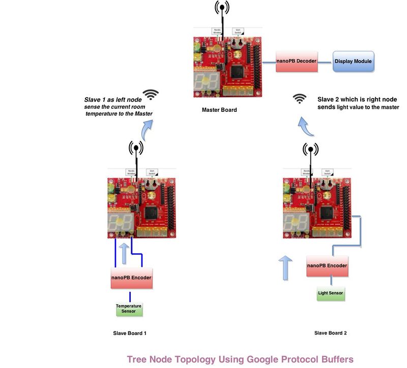
The network connection between the devices, that is, the master and the slaves is done in tree topology. So, we configured one microcontroller as master and two microcontroller as slaves. These slaves are connected to their slave wirelessly. The wireless connection between the microcontrollers is established using Nordic wireless transceiver. The wireless medium is by default configured at 2MBPS data rate. Once the data is encoded and ready to send, the data is sent at the specified rate. The data from two slave nodes is sent at different data rate so as to achieve the communication between the slower devices and faster devices and also to reduce the packet collision and subsequently loss of packets.
Software Design
How to write schema?
The .proto files start with a package declaration, which helps to prevent naming conflicts between different projects. Here we are naming package as tutorial. All generated structures will have tutorial as postfix. Now we define message definition. It is just an aggregate containing a set of typed fields. Many standard simple data types are available as field types, including bool,int32, float, double, and string. These data types are from the protobuffer library. To include other nanopb specific data types like int8, int16 we need to import nanopb.proto with certain definition changes. You can also add further structure to your messages by using other message types as field types. So these message are inter correlated and can be defined inside each other.In the given example we are defining a message filed named as SimpleMessage. Each of the message definition element must have a unique tag like “=1”, “=2”. It is used in the binary encoding. Tag numbers 1-15 require one less byte to encode than higher numbers, so as an optimization you can decide to use those tags for the commonly used or repeated elements, leaving tags 16 and higher for less-commonly used optional elements. Each field must be annotated with one of the following modifiers:
- required: a value must be provided, otherwise message will be considered “uninitialized”. Unless we are compiling in a debug mode, the compiler will throw error for all uninitialized required fields. We are using required field to define 32 bit integer.
- optional: this filed may or may not be set. If an optional field value isn't set, a default value is used. So it is advisable to set a default value. [default = value]. If no value is set compiler will set a FALSE or ‘0’ value. This will not throw any syntactical error but may interfere with the functionality of our code.
- repeated: the field may be repeated any number of times (including zero). The order of the repeated values will be preserved. It is advisable to limit the usage of repeated field as they are dynamically instantiated, so may consume memory. Never use required field with repeated field otherwise micro controller will go into infinite loop.
Example .proto configuration file
   message SimpleMessage
   {
         required int32 lucky_number = 1;
   }
Configuration of simple.options file:
- You can specifically instruct nanopb generator to use certain settings targeted at your micro controller. For example if you only want to use 16 bit integers then you can do it the two ways –
1. Editing nanopb.proto : You can edit nanopb.proto file according to your needs. This option should be used with precaution as it will change settings for all packages rather than a specific package. 2. Editing file.options: This is an advisable and favorable way of changing the settings as it will make changes only for that particular package. Basically this file modifies generator behavior.
Using functions from file.pb.h This auto generated file will contain various function and function definitions like has_lucky_number, set_lucky_number etc. Use them in your main program
Encoding:
- Nanopb uses streams for accessing the data in encoded format. The stream abstraction is very lightweight, and consists of a structure (pb_ostream_t or pb_istream_t) which contains a pointer to a callback function. There are certain rules for output stream used during encoding but the most important rule to remember is that one should not need to know message length during run time.
- This stream is stored into a buffer and this buffer along with message length is transmitted over a wireless or any other media.
- We are using a failsafe mechanism by additionally checking whether the message is encoded or not and assigning a Boolean value to status variable. This is very useful during debug.
Example of encoding
   uint8_t buffer[128];
   size_t message_length;
   bool status;
   /* Encoding */
   while(1)
   {
       SimpleMessage message;
       pb_ostream_t stream = pb_ostream_from_buffer(buffer, sizeof(buffer));
       message.lucky_number = 13;       // message content to be sent
       status = pb_encode(&stream, SimpleMessage_fields, &message);
       message_length = stream.bytes_written;
       if (!status)
       {
           printf("Encoding failed: %s\n", PB_GET_ERROR(&stream));
           return 1;
       }
   }
Decoding:
- At the receiver side message length is received first. It is necessary that input stream must know message length otherwise, decoding will fail.
- Now buffer data is received and is checked against the message length, if less data is received or last bit of buffer is not received, decoding will fail.
- Buffer data is decoded and input stream is formed.
Example of Decoding
   uint8_t buffer[128];
   size_t message_length;
   bool status;
   /* Decoding */
   while(1){
       SimpleMessage message;
       pb_istream_t stream = pb_istream_from_buffer(buffer, message_length);
       status = pb_decode(&stream, SimpleMessage_fields, &message);
       if (!status)
       {
           printf("Decoding failed: %s\n", PB_GET_ERROR(&stream));
           return 1;
       }
       /* Print the data contained in the message. */
       printf("Your lucky number was %d!\n", message.lucky_number);
   }
Design & Implementation
Implementation
This section includes implementation, but again, not the details, just the high level. For example, you can list the steps it takes to communicate over a sensor, or the steps needed to write a page of memory onto SPI Flash. You can include sub-sections for each of your component implementation.
Nanopb:
1. Create sensor.proto file in the nanopb/generator_bin directory or the directory in which nanopb_generator is set up earlier.
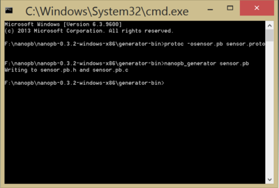
2. Open cmd -> protoc -osensor.pb sensor.proto. This will generate sensor.options and sensor.pb
protoc -osensor.proto
3. Cmd -> nanopb_generator sensor.pb. It will create header and source files, sensor.pb.c and sensor.pb.h.
nanopb_generator sensor.pb
4. Include sensor.pb.c/h files in the eclipse working directory either by including the path to these files or by copying them into the project folder.
5. As discussed earlier it is very important to include pb.h, encode.h, decode.h along with sensor.pb.h at the run time.
Wireless Mesh Network
|
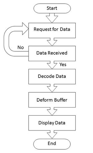
The Fig.1 shows the design flow of the master for wireless communication using Nordic wireless. As shown, 1. First, the master requests its slave node to give the required data. 2. Once the request is made, the master waits for the data to be received. If the data is not received until the expected timeout the request is again sent to the slave node. 3. As soon as the data is received, the data decoding is done. Since the data received is encoded by nano-Pb encoder, so to get the content of the message packet we have to decode the received message packet. 4. After decoding, an encapsulated google buffer is obtained that contains the original information sent by the device. So, this encapsulation is deformed and the required original data is extracted. 5. Once the original data is obtained, the data is displayed in more readable and understandable format. |
|
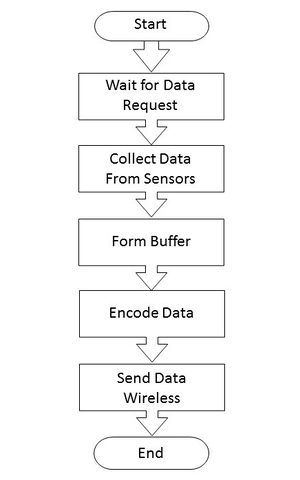
The Fig.2 shows the design flow of the Slave nodes for wireless communication using Nordic wireless. As shown, 1. The slave nodes, initially, waits for the request from the master. 2. Once the requested for data, the node collects the data from the sensors. 3. The collected data is then encapsulated and google buffer is formed. 4. Then, the data is encoded by nano-Pb encoder and is made ready to transmit over the wireless medium. 5. Send the encoded data through Nordic wireless.
|
Testing & Technical Challenges
Describe the challenges of your project. What advice would you give yourself or someone else if your project can be started from scratch again? Make a smooth transition to testing section and described what it took to test your project.
Include sub-sections that list out a problem and solution, such as:
1) Out of scope GPB functions displaying errors like closedir was not declared in this scope.
Solution: · Switched to Nanopb as its tiny footprint is suitable for 32 bit micro-controller.
2) Undefined filename nanopb_generator.py.
Solution: · Install python2.7 and link it to current working directory
3) Missing reference to nanopb_generator.
Solution: · Check whether you have included python27.dll in the working directory. · If it is absent copy it from C:\Windows\System32\python27.dll.
4) Eclipse error "No such file in the directory".
Solution: · Include all nanopb source and header files like pb_common.c/h, pb.h, pb_encode.c/h, pb_decode.c/h.
5) "multiple definitions of `main'".
Solution: · Main function may have been declared at multiple locations.
7) Initially packets are received but after some packets receiver stops receiving packets and IRQ led flashes.
Solution: · Wireless task is not instantiated and given higher priority so include this task into the main function.
8) While encoding the data we did not face any issue, but while decoding we faced one issue – Decoding Failed: Missing required field , End of stream
Solution: . The problem was the message_length (stream.bytes_written) field was incorrect. The length given was less than the number of bytes written in the buffer. So, we increased the size of message_length.
For example - This was a problem when light sensor was high. Initially the message_length was 7 but when high values were received it changed to 8. So we decided to give a more buffer size.
Conclusion
This project helped us in understanding the importance of data serialization in high bandwidth data transmission. The encoding and decoding of the data was trickiest part of the project. This project also gave insight of wireless mesh network and its working. We also interfaced Light sensor and temperature sensor to different slaves to make them transfer it to the parent node.
In overall this was great learning experience to know more in detail about ARM board and its various functionalities. The future scope of this project to include more slave nodes which would be fetching internet data using IOT modules to give different features such as real time weather information. By interfacing more slave controllers, wireless mesh network can be made more efficient to connect desired slave module with shortest distance path.
Project Video
https://www.youtube.com/watch?v=AUe2txSjOu0
Project Source Code
References
Acknowledgement
We would like to take this opportunity to thank our instructor Mr. Preetpal Kang for inspiring us to do challenging projects in embedded system. He has always been there to support and help us during this project. We are also thankful to TA’s namely Shashank and Dhawal who never let us loose the hope and lastly all team members who worked as a team throughout the project.
We would also like to thank our spring 2105 classmates for an enjoyable semester in CmpE244!
References Used
List any references used in project.
- Google's Nanopb web: http://koti.kapsi.fi/jpa/nanopb/docs/concepts.html
- Nanopb API references: http://koti.kapsi.fi/jpa/nanopb/docs/reference.html
Appendix
You can list the references you used.
