S15: Wireless Power Transfer System
Contents
Wireless Power Transfer System
Abstract

Wireless power transfer or wireless energy transmission is the transmission of electrical power from a power source to a consuming device without using solid wires or conductors. The technology dates back when Tesla first created his coil and the project is based on that idea. As the world is gaining momentum on wireless communication technology, there is a niche market for wireless power transfer for low power devices. This project explores one such idea and implementation for wireless power transfer from source to destination. The project is limited to near field application of such technology. The project does not explore the EMI/EMC aspects of the design.
Objectives & Introduction
Introduction
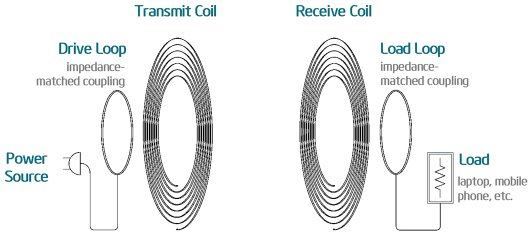
The project implements the principle of an inductively coupled power transfer system. A coil, attached to an AC power supply acts as a transmitter by the virtue of its time varying magnetic field and on the other end a receiver coil with magnetically induced current, drives a load motor attached to it. The two coils are aligned in such a way that the magnetic field interaction, and hence the power transfer is maximum. For this purpose, the receiver coil, mounted on a DC motor, makes a complete 360 degrees turn and the ADC continually monitors the voltage induced at each angle. The DC motor automatically goes to the position of the maximum sensed voltage and the coil starts driving the load motor attached to it.
Objectives
The main object of the project is to drive a motor wirelessly and making sure that the circuit is designed in such a way as to minimize the transmission losses and the load at the receiving end maintains a constant voltage without any fluctuations.
Team Members & Responsibilities
- Team Member 1
- Haroldo Filho - Lead Software Engineer
    - software architecture - define application abstraction layers, data flow.
    - motion control - develop means to implement motion including hardware specification and software interface.
    - mechanical fixturing - solve hardware mounting problem by fabricating holding fixtures with wood.
- Team Member 2
- Hemant Raman - Lead Hardware Engineer
    - investigate the physics behind wireless power transfer and fabricate copper transmission loops
    - design and implement signal conditioning and amplifier circuits for receiver and transmitter
    - design and implement ADC signal conditioning
- Team Member 3
- Hassan Naveed - Software Implementation
    - Learn wireless mesh driver and develop wireless mesh interface to send information between transmitter and receiver
    - Design and implement command parser for master/slave
    - Communication layer for tasks between master and slave
- Team Member 4
- Guangyu Chen - Software Implementation and integration
    - Integrate motion control and communication layers into multi tasking application
    - Design and implement command parser for master/slave
    - Refined the software architecture and coding style
    - Fix software bugs during the test section
Schedule
| Week# | Date | Task | Actual |
|---|---|---|---|
| 1 | 4/14 |
-Light an LED wirelessly -Test ADC: read 0~3.3V range -Test Nordic wireless: send/receive ADC value |
Completed. Initially there was an issue that the master node was missing some packets sent by the slave node. It was resolved by defining the two tasks using class method and then adding them to the task scheduler. Also there was a debate on the number of ADC samples to be taken in the ADC task. But after some deliberation, the number of samples was set to be 100. |
| 2 | 4/21 |
-Find channel frequency: 7.7MHz -Define wireless package structure: status and commands -Spec/order motor |
Completed |
| 3 | 4/28 |
-Implement wireless communication -Define software architecture layers -Define error code and handler -Implement motor control |
Completed, See software design section below for details |
| 3 | 5/5 |
-Evaluate ADC reading dynamics and design LPF -Implement software architecture layers |
Completed, uneven voltage waveform was giving inconsistent readings, therefore, the numbe of samples in the ADC task were increased to 1000 and their average value was used to calculate the voltage at the receiver end. |
| 3 | 5/12 |
-SW/HW Integration and testing. |
Completed, there were issues with finding the optimum spot for the receiver in the initial scan, but it was resolved. |
Parts List & Cost
| Item# | Qty | Reference | Part Name | Manufacturer | Description |
|---|---|---|---|---|---|
| 1 | 4 | C1-4 | CAPMICA1,10pF | IPC SM-782 STD. | MICA TANTALUM CAPACITOR 5.69 X 10.9 MM |
| 2 | 2 | D2-3 | DIO-MLL41 | IPC SM-782 | SURFACE MOUNT DIODE, MELF |
| 3 | 1 | L3 | IND-MOLDED,849nH | Regular Copper Pipe 15 inches Dia Loop | MOLDED INDUCTOR, 0.5" PIN SPACING |
| 4 | 2 | L1-2 | IND-UPRIGHT,100uH | UPRIGHT INDUCTOR WITH CORE | |
| 5 | 1 | D1 | MLED76 | MOTOROLA | INFRARED LED |
| 6 | 1 | R6 | RES-1/4W,100 ohms | RES BODY:100 CENTERS:500 | |
| 7 | 1 | R7 | RES-1/4W,10K | RES BODY:100 CENTERS:500 | |
| 8 | 1 | R5 | RES-1/4W,4.7K | RES BODY:100 CENTERS:500 | |
| 9 | 1 | R1 | RES-1/4W,5.6K | RES BODY:100 CENTERS:500 | |
| 10 | 2 | R3-4 | RES-1/4W,68 ohms | RES BODY:100 CENTERS:500 | |
| 11 | 1 | R2 | RES-1/4W_SMALL,5.6K | RES BODY:100 CENTERS:500 | |
| 12 | 1 | S1 | SW-NKK-JF15 | NKK JF15SP3C | NKK SPST N/O MOMENTARY PUSHBUTTON SWITCH |
| 13 | 3 | U1-3 | TO220-4_MOSFET |
Design & Implementation
The image below shows the project assembly. The loop on the left is the transmitter connected to a power supply while the one on the right is the receiver and mounted on a DC stepper motor (not visible in the picture) to change its orientation to the position of maximum power transfer. The load motor can be seen attached to the receiver loop and is driven wirelessly.

The sections below provide a descriptive overview of the hardware block and flow diagram.
Hardware Design
The Hardware design consists of major blocks an shown below. For the transmitter section, there are two methods of turning the system ON/OFF. One is a physical switch which maybe used as an override and the other is a software way of turning it ON/OFF. This switches the 60 Watts power supply module which is transmitted to the Copper loop (ref Pictures). The system runs at about 1.7MHz which is clear of the wireless signal transfer frequency of the Nordic wireless system (2.4GHz). For the Receiver, the loop which is tuned to the resonant frequency of the transmitter has very little losses and picks up about 24V 1.7MHz signal. The Power section has diodes which outputs RMS voltage of 1.41 x 24V AC= 33.9Vrms. Since all logics that the SJSU one board uses 3.3V a zener diode voltage regulator topology is implemented. A 1 ohm power resistor is used to sense the voltage on High Side and a current amplifier is used to set the gain of the system. The amplifier has common mode rejection ration of Bandwidth 500KHz and the signal is very noisy. A low pass filter was implemented in hardware so that the ADC could read stable values. Furthermore the software has a digital filter implemented to further stabilize the readings.

The hardware block diagram for the transmitter is:
The hardware block diagram for the receiver circuit:

Hardware Interface

The motor control part is implemented with a step and direction controller driving a bipolar 4 wire stepper motor. The system is open loop, as there is no encoder on the shaft or load, nor there is a way to detect step loss.
The drive is powered by 24V, and the logic signals are powered by 12VDC driven by the SJSUOne digital outputs.
The motor is a STP 3375 Nema 23 200 steps per rev, 166 in-oz. The motor driver takes 3 GPIO lines: enable, direction, and step.
It increments the rotor position by 1.8 degrees at every positive transition of the step input line as long as enable is asserted.
Software Design
For the software design, we define a layered architecture where each layer takes its services from the layer directly below it. The integrity of layered system was important as to ensure that no race conditions are generated where two tasks wait indefinitely for each other. The layers are:
- WIFI : Receive wireless packet from mesh network and pass the packet to communication layer for decoding.
- Communication : Decode the packet and execute corresponding actions.
- Motion Control : Control the motor to move to the desired position.

The wireless task on the master sends out a broadcast signal periodically to see what slave devices are present in the area and is always waiting on the slave nodes that may be present. The slave device, in our case the receiver, asks the master to start transmitting power on first waking up. The total data transfer that can take place through one packet is 32 bytes, of which 24 bytes is meaningful data and 8 bytes is overhead. Each time the slave or master spits out a packet, it waits for the acknowledgement on successful delivery by the virtue of wireless API used. Package structures between three layers:
Wireless Data Package Structure
|| 1 byte   | length - 1 ||
|| commands |    Data    ||
Status Package Structure
||   1 byte   |      1 byte      |      1 byte      |     x byte     ||
|| Error byte | ADC upper 4 bits | ADC lower 8 bits | Motor position ||
Error byte Structure
|| 8th bit  | 7th bit  | 6th bit  | 5th bit  | 4th bit  | 3rd bit  | 2nd bit  | 1st bit  ||
|| reserved | reserved | reserved | reserved | reserved | reserved | reserved | Busy bit ||
Motion Control Package Structure
|| 1 byte  |   1 byte    |   1 byte    |   1 byte    ||
|| Command | Parameter 1 | Parameter 2 | Parameter 3 ||
Motion Control Software Implementation
Implementation
The software implementation includes all the design of software architecture and wireless communication code. It also involves the main work flow for the whole purpose of the project.

The first steps of the software are purely handshaking protocol. The main task of this project is located at motion control of the motor.
- Slave sends the power request command first to the Master.
- Master requires the status of the Slave after receiving the power request.
- Slave then gives the feedback of it status.
- At last, Master drives the motion control task of the Slave.
Motion Control Task
The motion control is performed by a dedicated task. This task services two commands (expandable to more):
- Scan()
- Move(position)
SCAN:
The motor steps through one complete revolution, stopping at predefined intervals to acquire ADC samples.

It then acquires a certain number of samples while at a stand still, and averages them.
The result is stored in one element in the results array. the motor then carries on to the next ADC sampling position and readings are taken again.
At the end of 1 revolution, the scan is complete. the function get_max_energy_pos() is called which returns the position at which maximum ADC average was recorded. The number of steps to do is calculated by
steps_todo = get_max_energy_pos() - current_pos;
The direction pin is set depending on the sign of steps_todo. The scan operation has the following configurable parameters:
1- Number of ADC samples per stop: due to aliasing, this should be a big number, i.e. at least 1000, to account for the low sampling frequency compared to the oscillator at 1.7MHz.
2- Number of stops: how many times the motor will stop during one revolution to acquire samples. These stops are evenly spaced.
MOVE(distance):
The move(distance) command works by setting the direction bit based on the 'distance' parameter sign, and calculating how many toggles on the step line based on the angle.
Remember we have 200 steps per rev, and 2 toggles per step, so a 60 degrees move would result in 120 toggles.
As there is no position feedback (open loop moves), the current_pos variable holding motor position is maintained and updated by the software. When the system comes up position is initialized to zero. From then on, it is decremented or incremented at every positive step toggle based on the level of the direction bit.
In order to move, a "steps_todo" counter is loaded with the distance (number of toggles of the step line) and a motion task exhausts this counter at a frequency proportional to the desired speed.
Testing & Technical Challenges
Some of the challenges faced during the projects were:
Issue #1
ISSUE
The current sensing on the receiver through the 1 ohm resistor has a lot of noise riding on the signal. Using a software digital filter was not possible since it would put the software in a blocking mode for the duration of the capture. This would change the topology of the software architecture and deviate from being a good RTOS implementation. A quick alternative option needed to be implemented.
RESOLUTION
The resolution was:
1) to find a component with good common mode rejection ratio. LT1362 device was used, CMMR 500KHz.
2) to implement a Hardware filter before the ADC readings were taken. Even with hardware filter the signal was still noisy. Along with Hardware filter implementation, there was still noise on the signal and showed in terminal window of software. This variability in signal would cause "Hunting" on the transmitter platform where the platform would jitter. A software digital filter was implemented so the signal was smooth and some hysteresis was added to the PID control system of the tuning table.
Issue #2
ISSUE
The voltage output from the receiving antenna was ~33Vrms and all the electronics for the SJSU board were running at 3.3V logic. Even with voltage dividers it still presented a danger to damage the SJSU board ADC channel in case a large spike lasting long period was generated.
RESOLUTION
A very cheap and simple foldback voltage regulator was implemented which produced 3.3V DC. This ensured that the absolute maximum voltage that the ADC would see was 3.3V. To further protect the SJSU board peripherals, a Instrumentation amplifier block was placed between the 3.3V supply and the ADC. This gave us some confidence that in the worst condition the damage will first be sustained by the Instrumentation amplifier and not the ADC channel.
Issue #3
When we first implemented the software layers, we handled and decoded all the wireless packages in the top level while the lower two layers also required data feedback to the top level. In this case, the top level needed to listen two queues or to fill feedback to the wireless quese which are both impossible. So we changed the whole architecture and moved the decoding and wireless feedback to the middle layers that made the whole software simpler without any layer violation.
Conclusion
Wireless power transfer was a very unique project since it had not been done before in CmpE 244. We came across really complex hardware problems like noise, signal integrity and signal conditioning cannot be solved by software or hardware alone. It takes a combination of the two to solve it. For the software part, we learned how to build and design a layered architecture of firmware where each layer interacts with the layers adjacent to it. It also posed a lot of problems initially since every new function that we would add or modify would somehow violate the layered architecture. But eventually we got it right and it gave us a great overview as well as insight as to how professionals in the industry actually design and implement there software projects.
Project Video
Project Source Code
Our source code is mainly located at L5_Application/source/power_wifi.cpp
References
Acknowledgement
We would like to thank our instructor Preet for always inspiring and encouraging us to learn and and explore new projects related to embedded systems. We really appreciate his patience and his guidance and whenever we needed him, he was just an email away always willing to help and point us in the right direction.
References Used
http://www.nxp.com/documents/user_manual/UM10360.pdf
http://www.socialledge.com/sjsu/index.php?title=SJ_One_Board
http://www.freescale.com/files/sensors/doc/data_sheet/MMA8452Q.pdf
http://www.onsemi.com/PowerSolutions/product.do?id=MBR3100
http://html.alldatasheet.com/html-pdf/126471/MOTOROLA/1N5822/383/1/1N5822.html
http://socialledge.com/docs/wireless_8h.html
http://www.socialledge.com/sjsu/index.php?title=Low_Powered_Mesh_Network_stack
Appendix
You can list the references you used.