S16: Expendables
Contents
Wireless LED Text Display
Abstract
Wireless LED text display allows users to display text from anywhere using internet. Wireless text display scrolls the multicolored text message on the serially connected LED panels. To enable the wireless transmission, the webapp is accessing the IP address to which the raspberry pi is connected. Project explores the idea of displaying a text message conveniently from any place over internet.
Objectives & Introduction
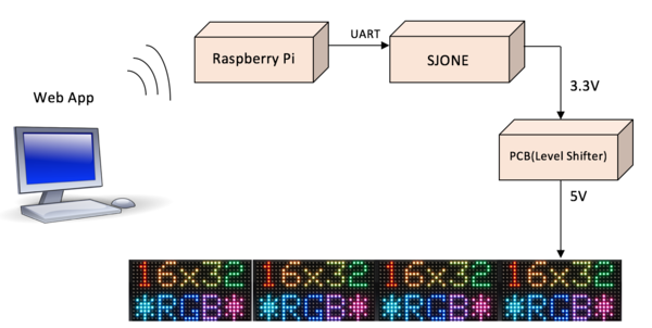
The focus of the project is to develop an embedded design to display message wirelessly on the LED panels. Internet is selected as the medium to send the message wirelessly. Webapp is developed to provide the text input. On the Hardware side, Raspberry pi is connected to internet either by Wi-Fi or Ethernet. The Text sent from the webapp is received by Raspberry pi. Raspberry pi transmits the data serially through UART to SJ-ONE board. SJ-ONE board consists of code to drive the LED panels and connects to LED panels through PCB interface. PCB board consists of Lever shifter buffer IC required to protect SJ-ONE board GPIO pins and level shift the signals.
The Objectives of the Project are as follows:
1. Driving a single LED panel without any built-in controller through GPIO.
2. Driving multiple LED panels, which are connected serially.
3. SJONE board connection with LED panels.
4. PCB board creation to drive the voltage levels of 3.3v SJONE board and 5.0V LED panel.
5. Raspberry pi connection with the SJONE board.
6. Webapp creation to send the text message to raspberry pi.
Team Members & Responsibilities
- Asmita Deshpande and Sameena Meer
- Raspberry Pi Setup
- UART Setup
- Python Magic
- PCB Debugging
- Soldering
- Sami Ullah and Sant Prakash Soy
- AWS Server
- MQTT
- PCB Design
- LED Driver
Schedule
| Sl. No | Start Date | End Date | Task | Status | Actual Completion Date |
|---|---|---|---|---|---|
| 1 | 3/07/2016 | 3/13/2016 | Components buying | Completed | 3/18/2016 |
| 2 | 3/14/2016 | 3/20/2016 | LED panels study | Completed | 3/20/2016 |
| 3 | 3/28/2016 | 4/03/2016 | Raspberry Pi 3 study | Completed | 4/03/2016 |
| 4 | 4/04/2016 | 4/10/2016 | Pixel Driver Design | Completed | 4/20/2016 |
| 5 | 4/11/2016 | 4/17/2016 | PCB Design | Completed | 3/30/2016 |
| 6 | 4/18/2016 | 4/24/2016 | Testing Text Display | Completed | 4/20/2016 |
| 7 | 4/25/2016 | 5/01/2016 | UI Webserver | Completed | 4/25/2016 |
| 8 | 5/02/2016 | 5/08/2016 | Final Testing and Debugging | Completed | 5/21/2016 |
Parts List & Cost
| Sl. No | Part Name | Source of purchase | Quantity | Cost($) |
|---|---|---|---|---|
| 1 | Raspberry Pi 3 | Adafruit | 1 | 44.49 |
| 2 | LED panels | Preet | 4 | 0 |
| 3 | 74HC245 | Digikey | 2 | 2 |
| 4 | ATX PSU | Amazon | 1 | 20.94 |
| 5 | Molex Connectors | Amazon | 4 | 15 |
| 6 | PCB | OSH Park | 3 | 30 |
| 7 | Aluminum Extrusion | Adafruit | 1 | 7.50 |
| 8 | Oval T-Nut | Adafruit | 50 | 9.95 |
| 9 | Power Adapter for Raspberry PI | Amazon | 1 | 9.99 |
Design & Implementation
Hardware Design
LED Panels Working
The display panels use multiplexing to draw picture information, which means that the rows and columns are updated fast than the human eye can process. If the updating speed is fast enough, eyes will see a complete picture without flickering. The updating process is as follows
- Select the row to be updated.
- Output the desired column data on selected row.
Row Selection
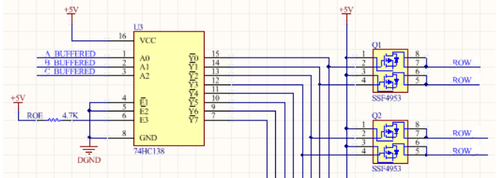
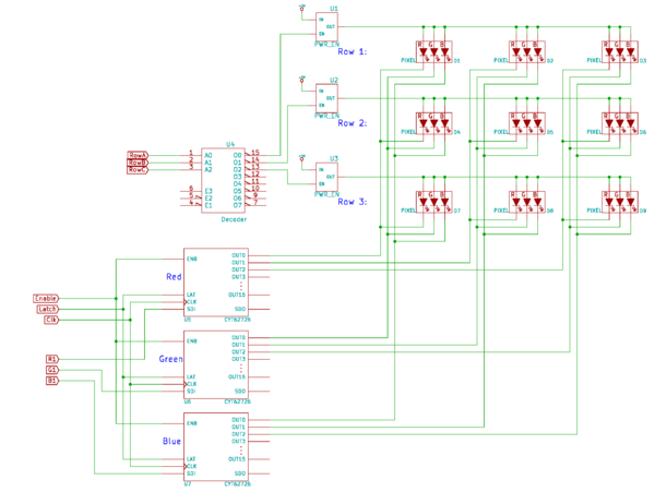
Row selection is done by using a 3-to-8 address decoder (74HC138D). There are three address inputs to the display marked A, B and C. Based on the truth table, only one input is active (low) at a time.
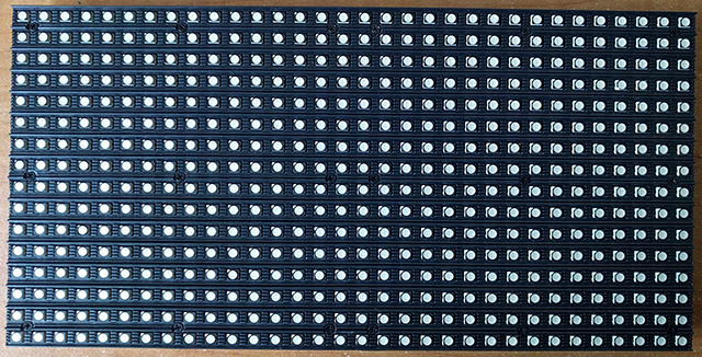
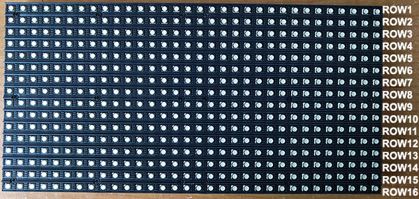
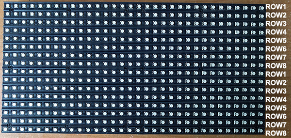
Since the panels has 16 rows, the 3-to-8 address decoder select rows in parallel. For example, when the 1st row (Row1) is selected, it also selects the 9th row (Row9). Using this technique implies that we must supply data for the columns for two unique rows at a time.
The outputs of the decoder is connected to a P-Channel MOSFET, because the decoder itself can only handle low currents and cannot drive a row of LEDs directly. The P-Channel MOSFET provides the high current needed to drive a row of LEDs.
The decoder outputs are shared between every 8 outputs (1 and 9, 2 and 10, repeating that pattern until row 8 and 16).
Column Selection
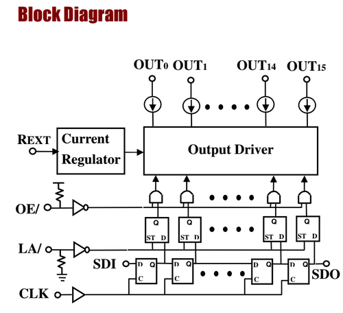
The column data is stored in a 16-bit serial-in, parallel-out shift register. Since the display is 32 pixels wide, two shift registers must be chained together. The shift register is designed to work with LEDs and implements a constant-current system that ensures the LED brightness remains uniform. The panels that we are using utilize SCT2026 shift registers. These are 16-bit Serial-In/Parallel-Out registers.
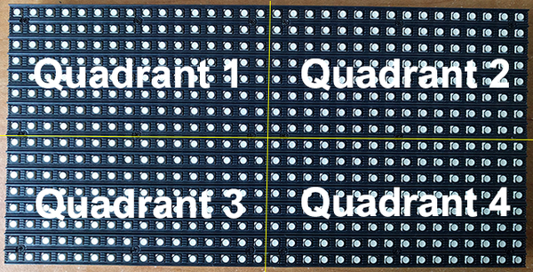
There are 12 of these shift registers on the display. 3 each are used to hold the Red, Green, and Blue data for 1 of 4 quadrants of the display. (3 colors * 4 quadrants = 12 chips)
For drawing 16 rows using the 8 outputs of the decoder, we must have unique data for each row pair. When Row 1 and Row 9 are selected, we must provide each row with unique data. This forces us to use two different shift registers for each row pair, an upper register and a lower register. Because of this, the display is divided into an upper half and a lower half. The data is shifted into the top half via the R1, G1 and B1 signals on the connector. The bottom half’s data is supplied by the R2, G2 and B2 signals on the connector. Then, since our display is 32 pixels wide, we must use 2 shift registers to hold all 32 bits of pixel data for a single row. This creates the left and right halves of the display.
Each quadrant of the display is controlled by 3 shift registers, one for each color. First, Row 1 and Row 9 are selected. 32 bits of data are shifted into each color’s shift register (R1, G1, B1), and then latched. At the same time, 32 bits of data are also shifted into each color’s shift register for the bottom half (R2, G2, B2), and then latched. The process repeats 7 more times, each time incrementing which rows are selected, until every line has been updated.
In summary in order to display something on the LED panels the following steps needs to be performed by the driver
- Shift the pixel data for row 0 into the top column drivers and the pixel data for row 16 into the bottom column drivers using the R1, G1, B1, R2, G2, and B2 data inputs and the SCLK shift clock signal.
- Assert the blanking signal to blank the display.
- Set the address input to 0.
- Latch the contents of the column drivers‘ shift registers into the column drivers‘ output registers using the LATCH signal.
- De-assert the blanking signal to display rows 0 and 16.
- Wait some fixed amount of time.
- Repeat the process for each of the pairs of rows in the display.
- Repeat the entire process at least 100 to 200 times per second to prevent flicker.
Hardware Interface
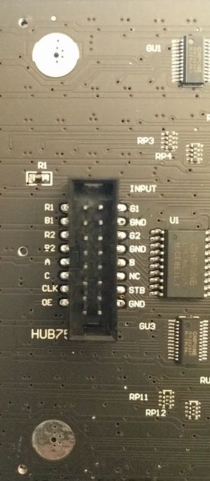
The connector on the RGB panels is called a Hub75 interface. Each panel typically has two ports, one is the input and the other is the output to chain additional panels.
PCB Design
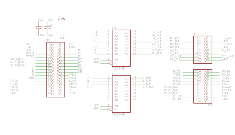
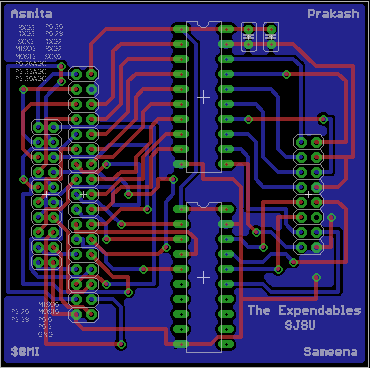
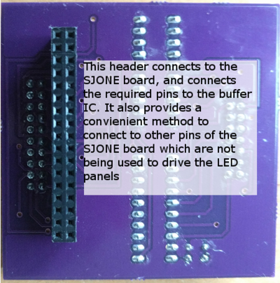
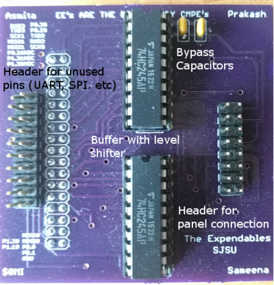
The LED panels use 74HC245 line drivers, these transceivers require 5v logic levels whereas the SJONE board only supports 3.3v logic. In order to drive the LED panels from 3.3v GPIO pins of the SJONE board, level-shifting IC is used to level shift signals from 3.3V to 5V and shield the SJONE board GPIOs from overloading. For this purpose, and to make it easier to connect the panels to the SJONE board a PCB was designed in EAGLE. The PCB attaches to GPIO pins of SJONE board and provides easily accessible, level-shifted output for the LED panels. The PCB also breaks-out free pins so that they can be used for other purposes.
Software Design
Classes
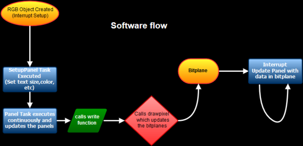
The software for driving the LED panels is divided into two classes, GFX and RGB. The GFX class implements all the methods for drawing various characters on the LED panels, setting their heights, and colors. It does not concerns with how the LED panel works, and just assumes the LED panels to be a canvas to draw on. The GFX class has virtual functions, which deals with how to actually display something on he panels. These virtual functions are implemented in the RGB class, which inherits from GFX class.
Tasks
Further there are three tasks to get the LED panel running, and displaying the required task. The first task is setuppanel, which has a low priority. This task only runs once, and sets all the parameters like text size, wrap, etc. The second task called panel runs continuously, and has high priority because it is responsible for displaying the text and refreshing the LED panels. The third task is simply called gpioTask, it is a medium priority task, and is reponsible for receiving the text to display over UART from raspberry PI.
Web Application
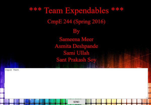
A webapp was designed hosted on Amazon AWS. The raspberry pi connects to the service provided by the webapp, any text entered on the webapp is transmitted to raspberry pi, which sends the received text over UART to the SJONE board to be displayed on the LED panels.
Implementation
Fonts
The fonts displayed on the LED panels are implemented as an array of hexadecimal values, and in alphabetical order.
This section includes implementation, but again, not the details, just the high level. For example, you can list the steps it takes to communicate over a sensor, or the steps needed to write a page of memory onto SPI Flash. You can include sub-sections for each of your component implementation.
PWM
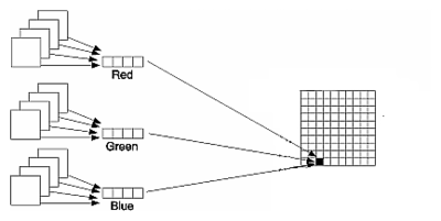
The code tries to use a technique called Binary Code Modulation to control the colors of the display. Driving with Pulse Width Modulation (PWM) would turn the LED on for an amount of time proportional to the desired brightness, then turn it off for the rest of the period. BCM divides the period into binary-length segments (1x, 2x, 4x, etc), and turns the LED on or off for each of these segments according to the bits of the LED’s desired brightness. The pixel data must be divided up into bitplanes. These bitplanes are nothing but an array in which each element is a single bit from a color value in the displayed image. Each pixel would require three separate bitplanes, one for each color element. However to drive the display, all three colors are written out for two different pixels at the same time. The code stores six bits, one from each bitplane, together in a byte. This way the bytes are immediately ready to be written to the GPIO port during the interrupt. The code refers to the arrays of ready-to-write bytes as “planes,”. In each interrupt (RGB::updateDisplay) a byte from the appropriate plane is written out to the GPIO port and the delay until the next interrupt is set.
 void refreshISR(void)
 {
   activePanel->updateDisplay();
 }
Messaging Protocol
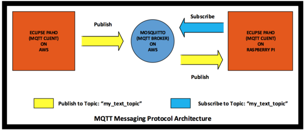
MQTT (Message Queue Telemetry Transport) is the messaging protocol used for sending text from our webapp to the LED panels. MQTT is a light weight messaging protocol that uses publisher and subscriber architecture. Publishers are the devices that send data and subscribers are the ones that receive data. Devices that need to receive data must have MQTT client program such as Eclipse Paho running on them. Furthermore, the client program running on these devices need to subscribe to topics from which they want to receive data. The devices that need to send data also must have Paho MQTT client running on them. To send data, devices have to publish data to certain topics. There is another program that sits in between the sending and the receiving devices which is called an MQTT broker. The job of an MQTT broker is to receive data from senders and then send the data to receivers with appropriate topics.
The figure below shows our MQTT messaging protocol architecture. The architecture shows an eclipse Paho client program, running on AWS (Amazon Web Service), is publishing text on a topic called "my_text_topic". It also shows the Paho client program running on raspberry pi subscribing to the topic "my_text_topic". The MQTT broker known as Mosquitto running on AWS receives text from the publisher publishing on topic "my_text_topic" and sends the data to the receiver that has already subscribed to topic "my_text_topic".
Testing & Technical Challenges
Describe the challenges of your project. What advise would you give yourself or someone else if your project can be started from scratch again? Make a smooth transition to testing section and described what it took to test your project.
Include sub-sections that list out a problem and solution, such as:
Issue #1: No Datasheets
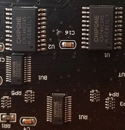
The RGB LED panels we used did not have any datasheets available for them, this was worsened by the fact that they also did not have a standard interface to drive them like SPI or I2C. We decided to resolve this by studying the datasheets of the integrated circuits which were on the panels, but soon we bumped into another problem. The IC's were made by an obscure manufacturer called "CHIPONE".
Issue #2: Raspberry PI 3
Initially we planned to use a PI 3 because of its built-in wifi capability, but while testing it we found out that it was very unstable, and was unable to have a consistent connection. Therefore we decided to use PI 2, and share the internet connection over Ethernet through a laptop.
Issue #3: Shapes and Graphics
Though we were successfully able to display text on the display panels. We were unable to display images. The images would require extra effort on the transmission side, as the panels are very low resolution, so whatever image has to be displayed will need to be converted to a lower resolution first.
Conclusion
In this project we were given a set of RGB LED matrix to design something useful out of it. In the early parts of this project, our vague goals led to a broad scope of ideas, and a lack of structure. Choosing areas of focus helped us to narrow our design and choose an approach that is feasible. Many aspects of this project involved learning how particular processes work, including the PCB layout in eagle, performing DRC on it, sending it to a PCB house (OSHPARK), and making sure it fulfills all the restrictions imposed by them to have a working PCB. It also helped us learn about virtual classes, and polymorphism both of which our software utilizes. The design goals that we set for ourselves were completed, though there is much that can be improved upon. We have laid the foundation on which future projects can be done like displaying shapes, and images on the panel. In proving our concept, and designing a system that solves the problems we were presented with, however, we feel we have achieved success.
Project Video
Project Source Code
File:CMPE244 S16 Expendables Wireless LED Text Display.zip
References
Acknowledgement
We would like to thank Preet for the guidance and providing us LED Panels used in this project.
References Used
http://bikerglen.com/projects/lighting/led-panel-1up/
http://www.batsocks.co.uk/readme/art_bcm_1.htm
http://flask.pocoo.org/
http://www.w3schools.com/

