S18: Audio Spectrum Analyzer with Graphics Display
Contents
Audio Spectrum Analyzer with Graphics Display
Abstract
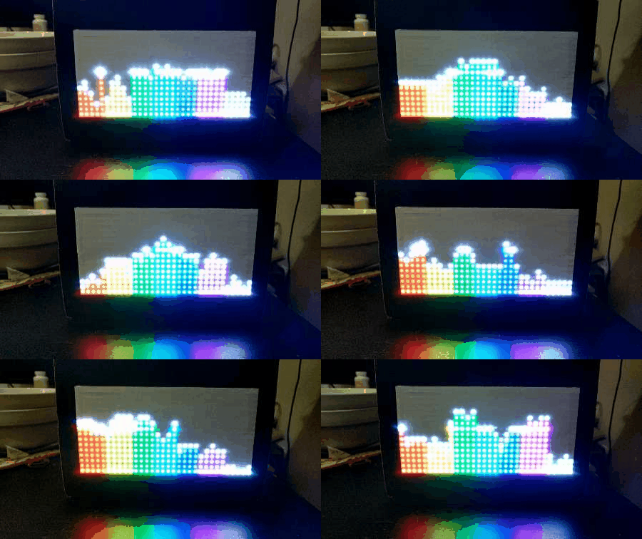
Music is an essential element of human life. When someone hears a certain piece of melody that represents their current mood, they will likely to have body responses and sentimental fulfillment to it. Nowadays, music is often recorded electronically. In such conditions, the music is represented by different frequency bands that operate together. While the sound travels through the air and goes into our ears, one may wonder why couldn't we also visualize the different frequency bands through our eyes, as this essentially provides a dynamic graphical layout of the melody as time goes on. Therefore, our team set foot on this project, which uses an RGB LED matrix to display graphics based on the dynamic MP3 audio frequencies. An MP3 audio decoder board will be used to connect to one of the SJOne board, which contains the MP3 files in its SD card, to decode MP3 files; and it then sends the decoded data to the graphic equalizer. The user will be able to see graphics on the RGB LED matrix instantly while playing MP3 files. We also implemented some control buttons to modify the playing music. The functionalities include pause music, resume music, skip music, display playing modes, show the matrix's display and rotate the display with a different orientation.
Objectives & Introduction
Introduction
Our team split the project into four different parts: The audio decoder, the audio analyzer, the RGB LED Matrix, and the PCB design. Thus, two of our team members split the hardware and the software parts, some they worked together, some they worked individually. The other team member wanted to work on the PCB design. The audio decoder decodes the MP3 files and outputs an analog signal that represents the sound. The Graphic Equalizer part converts the analog audio input to a digital output that can be parsed by the RGB LED Matrix. In other words, it created a formatted data representation. The RGB LED Matrix part mainly focused on parsing the converted data and drive the RGB LED screen to display the dynamic frequencies of the signals.
Objectives
We followed proper engineering and testing practices to design and implement the following:
- Design equalizer PCB
- Interfacing audio decoder pin layout and system design
- Interfacing audio equalizer pin layout and system design
- Interfacing RGB LED matrix pin layout and system design
- Implement audio decoder driver
- Implement audio equalizer driver
- Implement RGB LED matrix driver
- Integrate equalizer and RGB LED matrix
- Test overall system and program
- Preparing whole project hardware design as a demo ready package
Team Members & Responsibilities
- Lorenzo Javier
- Audio Decoder Interfacing w/ SJOne Board (MP3 Driver)
- Graphic Equalizer Interfacing w/ Audio Decoder (Pin Layout/System Design)
- RGB LED Matrix Initialization Interfacing w/ SJOne Board (RGB LED Driver)
- Record, Edit, and Post the Demo Video on YouTube
- Jason Lin
- Graphic Equalizer Interfacing w/ SJOne Board (Audio Analyzer Driver)
- RGB LED Matrix Light Show Algorithm & Initialization Interfacing w/ SJOne Board (RGB LED Driver)
- Extra/Additional Functionalities (MP3 pause, resume, and skip / display modes, accelerometer direction/rotation, splash/pause/skip screen, and entertainment bar/dot and spinning)
- Design and Implement the Display Shadow Box (Containing All Components)
- Bohan Liu
- PCB Design
Schedule
| Week# | Ending date | Task | Actual |
|---|---|---|---|
| 1 | 4/15 |
|
Completed |
| 2 | 4/22 |
|
Completed |
| 3 | 4/30 |
|
Completed |
| 4 | 5/7 |
|
Completed |
| 5 | 5/14 |
|
Completed |
| 6 | 5/21 |
|
Completed |
Parts List & Cost
| # | Name | Purchase Location | Description | Quantity | Cost |
|---|---|---|---|---|---|
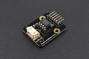
| 1 | Audio Analyzer | Amazon DFROBOT | Graphic Equalizer Display Filter ‑ MSGEQ7 Breakout Board | 1 | $21.55 |
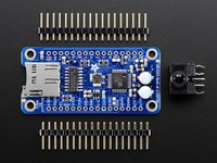
| 2 | Audio Decoder | Adafruit | VS1053 Audio Decoder Breakout Board w/ Breadboard-Friendly 3.5mm Stereo Headphone Jack | 1 | $24.95 |
| 3 | RGB LED Matrix (16x32) | Adafruit | RGB LED Matrix Panel (16x32) | 1 | $24.95 |
| 4 | Jumper Wires | Amazon | Variety of Male/Male, Male/Female, & Female/Female Breadboard Jumper Wires | 120 | $7.49 |
| 5 | Breadboard | Amazon | Breadboard - Small | 1 | $8.21 |
| 6 | SJOne Board | Social Ledge | LPC1758 Chipset | 2 | $160.00 |
| 7 | 5V 2.4A Portable Battery | Amazon | Portable Power Supply (5V 2.4A) | 1 | $10.99 |
Design & Implementation
This section provides an overview of our design methodology for the MP3 audio decoder, the audio analyzer graphic equalizer, and the RGB LED matrix. First, we analyze these components independently. Then we describe the integration of all components.
Hardware Design
MP3 Audio Decoder
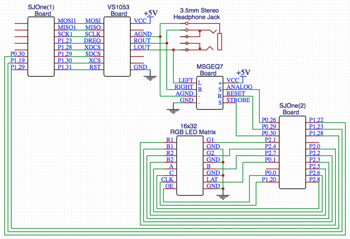
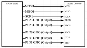
The VS1053 MP3 audio decoder breakout board connects to the SJOne board through the SPI protocol (MOSI, MISO, SCLK, XDCS) for sending/receiving data.
The other pins DREQ, XCS, SDCS, and RST are connected to the SJOne board pins as GPIO functionality.
The AGND, LOUT, and ROUT pins are split out between the 3.5mm stereo headphone jack and the audio analyzer breakout board.
Here is a description of the pin functionalities as follows:
- XCS -> a chip select pin for SCI operation (to control settings, i.e. volume)
- XDCS -> a chip select pin for SDI operation (to enable data transfer)
- RST -> a reset pin to perform a hard reset of previous data/settings
- DREQ -> a status pin to notify when the buffer is ready to receive more data (busy = 0, ready = 1)
- SDCS -> a chip select pin for enabling/disabling the MicroSD card slot
- AGND -> a common ground pin
- LOUT -> the analog left audio data pin
- ROUT -> the analog right audio data pin
The remaining pins are VCC (5V), and GND (Ground).
Graphic Equalizer
The Audio Analyzer breakout board features the MSGEQ7 graphic equalizer display filter. It splits the analog audio input into seven different frequency bands. The value of the seven frequencies measured are as follows: 63Hz, 160Hz, 400Hz, 1kHz, 2.5kHz, 6.25kHz and 16kHz. It connects to the SJOne board through the ADC (ANALOG) protocol for reading the values of seven frequencies.
The other pins, RESET and STROBE, are connected to the SJOne board pins as GPIO functionality.
Here is a description of the pin functionalities as follows:
- ANALOG-> a chip select pin for Output analog signal (for ADC on SJOne board to read)
- RESET -> a chip select pin for Input GPIO signal (to get reset signal from SJOne GPIO)
- STROBE-> a chip select pin for Input GPIO signal (to be precisely controlled to read the analog outputs properly)
The remaining pins are VCC (5V), and GND (Ground).
RGB LED Matrix
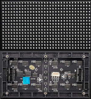
The 16x32 RGB LED Matrix features as a display panel. It has two IDC connectors INPUT and OUTPUT on the back to connect multiple panels, but we only use one on this project. Its RGB data is separated in 1 and 2, 1 represents the upper half of the matrix, 2 represents the lower half. This matrix has a decoder which takes ABC as input to decode the corresponding row on both upper and lower half of the panel. Each color pin has a 32-bit shift register. With the clock signal implemented with the shift register, we can control every single LED's color.
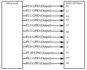
The Latch signal is to indicate the end of the data line. It connects to the SJOne board through pins (R1, G1, B1, R2, G2, B2, A, B, C, CLK, LAT, OE) as GPIO functionality.
Here is a description of the pin functionalities as follows:
- R1 -> a chip select pin for Input GPIO signal (to control upper panel's R data)
- G1 -> a chip select pin for Input GPIO signal (to control upper panel's G data)
- B1 -> a chip select pin for Input GPIO signal (to control upper panel's B data)
- R2 -> a chip select pin for Input GPIO signal (to control lower panel's R data)
- G2 -> a chip select pin for Input GPIO signal (to control lower panel's G data)
- B2 -> a chip select pin for Input GPIO signal (to control lower panel's B data)
- A -> a chip select pin for Input GPIO signal (to select both upper and lower panel's row bit 2)
- B -> a chip select pin for Input GPIO signal (to select both upper and lower panel's row bit 1)
- C -> a chip select pin for Input GPIO signal (to select both upper and lower panel's row bit 0)
- CLK -> a chip select pin for Input GPIO signal (to get clock signal from SJOne board)
- LAT -> a chip select pin for Input GPIO signal (to get latch signal from SJOne GPIO)
- OE -> a chip select pin for Input GPIO signal (Output enable to cascade LED matrix)
The remaining pins are VCC (5V), and four GND (Ground).
PCB Design
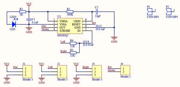
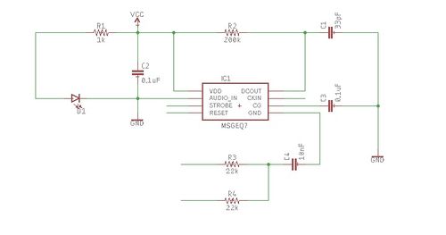
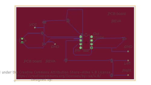
In the PCB Design section, we mainly tried to design the PCB layout of the Graphic Equalizer board. The board contains a MSGEQ7 chip as its main component. In the order to be connectable to other modules, we added surrounding elements to support this. The main difficulties involved are using the elements with correct parameters and correctly wiring them.
| # | Description | Quantity |
|---|---|---|
| 1 | 1K Resistor | 1 |
| 2 | 200K Resistor | 1 |
| 3 | 22K Resistor | 2 |
| 4 | VCC | 1 |
| 5 | GND | 2 |
| 6 | LED | 1 |
| 7 | 0.1 uF Capacitor | 2 |
| 8 | 10 nF Capacitor | 1 |
| 9 | 33 pF Capacitor | 1 |
| 10 | MSGEQ7 Module | 1 |
Below is the schematic for PCB design. In the center is the MSGEQ7 chip. By adding surrounding elements, we made it connectable to other modules.
Below is the diagram for PCB board layout. In the center is the MSGEQ7 chip. The components are wired together, the pins are labeled, and the board is titled.
Hardware Interface
This section briefly describes some of the hardware communication protocols between the various master/slave devices. Most of the information here is repeated from the previous Hardware Design section.
MP3 Audio Decoder
The audio decoder was driven by the several pins mentioned in Figure 1 from the Hardware Design section. Its main interface is SPI, which is great for transferring large amounts of bytes within a short amount of time. This is especially useful for live audio streaming, otherwise, there would be many glitches or a slow down of audio playback.
The SJOne's audio decoder driver included opening & reading the .mp3 files that were loaded onto the microSD card, which was inserted into the microSD card slot on the SJOne board, not the audio decoder board.
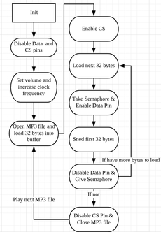
In order to drive the MP3 audio decoder, there are a few steps need to do:
- Step 0: Initialization. Set 5 pins as GPIO Output, while the other 3 are SPI format (MOSI, MISO, SCLK).
- Step 1: Disable the data pin and chip select pin, for modifying settings over SCI.
- Step 2: Set volume rate, and increase the clock frequency of the audio decoder.
- Step 3: Open MP3 file to start playing from SJOne.
- Step 4: Enable the chip select pin, and enter while loop.
- Step 5: Load next 32 bytes, take semaphore, enable data pin, send 32 bytes, disable data pin, give semaphore, and wait for status signal from audio decoder.
- Step 6: Repeat step 5 until there are no more bytes from the loaded MP3 file.
- Step 7: Disable chip select pin, close MP3 file.
- Step 8: Start at step 3 if there are more MP3 files to be played.
Graphic Equalizer
The audio analyzer was driven by the several pins mentioned in the Hardware Design section. Its main interface was GPIO, which was used to reset the analog signals coming in. The other main interface was the analog audio input from the left and right audio pins, coming from the audio decoder. We talk about it more in the Software Design section.
RGB LED Matrix
The RGB LED matrix was driven by the several pins mentioned in the Hardware Design section. Its main interface was GPIO, which was used for every single pin including CLOCK (besides GND). There were sets of GPIO's which controlled the top half and bottom half of the matrix. Each top and bottom half had it's own Red, Green, and Blue GPIO connections for controlling the color of each individual LED. The other important GPIO pins were for the LATCH, CLOCK, and OUTPUT ENABLE. The LATCH was used to set each rows' LED color data after it was loaded into its register. The CLOCK was manually controlled by a GPIO to ensure that the SJOne board could have enough time to send all the RGB signals.
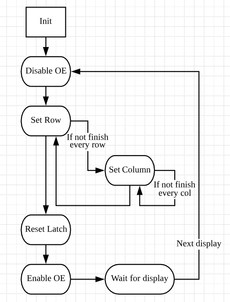
In order to drive the RGB LED display, there are a few steps need to do:
- Step 0: Initialization. Set all 12 pins as GPIO Output.
- Step 1: Disable Output Enable pin by setting it high in order to be able to change the display.
- Step 2: Set A, B, and C pins to select a row.
- Step 3: Set the first column of this row, then set the clock high and low to shift to the next column.
- Step 4: Repeat step 3 to finish setting in this row.
- Step 5: Repeat step 2 through 4 to finish setting every row.
- Step 6: Latch the contents of the shift registers into the output registers by resetting the Latch signal.
- Step 7: Enable the Output Enable pin by setting it low to display.
- Step 8: Wait with a fixed time for RGB LED matrix to display.
- Step 9: Repeat step 1 through 8 for another display
Functionalities
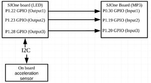
For functionalities purpose, we use the onboard acceleration sensor through the I2C protocol to read values from the accelerometer and three GPIO pins to connect two SJOne boards together. Hence, one SJOne board can set GPIO signal to implement interrupt function to another SJOne board.
Software Design
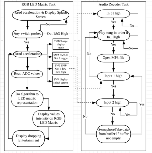
The following diagram shows how two of our tasks are being integrated. The Matrix task reads the analog values from the Equalizer and uses them to do an algorithm and display on the LED Matrix. The analog input values are converted to digital using the SJOne board ADC. The converted values are then sent to the queue to which the LED Matrix task is listening.
MP3 Audio Decoder
The below code snippet contains part of the MP3 audio driver from the SJOne. This while loop will constantly transfer data to the audio decoder's buffer via the SPI protocol, take data out of buffer via Mutex, and will sit idle until the audio decoder sends a status signal saying it's ready for more data.
//Code snippet

while(1)
{
   while(!mp3Ready())
   {
       if(need_data == true)
       {
           if(FR_OK != file_read)
           {
                file_close; //ERROR: Could not read mp3 file or no data left to read
           }
           need_data = false;
        }
   }
   if(need_data == true)
   {
       if(FR_OK != file_read)
       {
           file_close; //ERROR: Could not read mp3 file or no data left to read
       }
       need_data = false;
   }
   if(xSemaphoreTake(xMutex, portMAX_DELAY))
   {
       enable XDCS;
       for(y < sizeof mp3DataBuffer)
       {
            transfer(mp3DataBuffer[y]);
       }
            disable XDCS;
            xSemaphoreGive(xMutex);
   }
   need_data = true;
   if(bytesRead == 0) break;
}
while(!mp3Ready());
disable XDCS;
file_close;
Graphic Equalizer
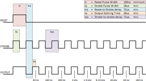
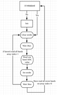
The diagram below shows how the MSGEQ7 chip outputting the analog signals. The software needs GPIO pins to generate the strobe signal and reset signal. The strobe signal needs to be precisely controlled in order to read the analog values properly, so we follow in this strobe timing diagram to read the analog values. At first, we initialize by setting and clear the reset pin, then read the first values 72us after setting and clearing the strobe pin and repeat to read all other bands.
//Code snippet

if(!isInitialized)
{
   current time = system get uptime + 36;
   while(system get uptime < current time);
   set_pin(RESET_PIN);
   current time = system get uptime + 36;
   while(system get uptime < current time);
   clear_pin(RESET_PIN);
   set_pin(STROBE_PIN);
   isInitialized = true;
}

for(i<7)
{
    clear_pin(STROBE);
    current time = system get uptime  + 36;
    while(system get uptime < current time){}
    values[i] = read_pin_value;
    set_pin(STROBE);
    current time = system get uptime  + 36;
    while(ystem get uptime < current time){}
}
RGB LED Matrix
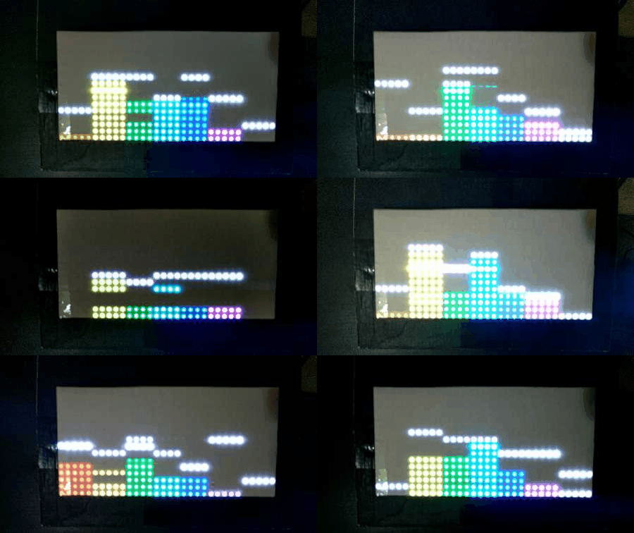
The below code snippet is from the RGB LED matrix driver of the SJOne. The conditions below are comparing the several spectrum frequencies that were divided by the audio analyzer board and sent back to the SJOne. Depending on those values, the color and height of the matrix array will be set respectively.
Light show algorithm
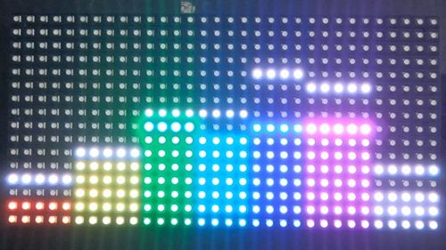
At first, it dequeues the ADC values into an array which represent seven different bands and set which column they represented. Next, uses the ADC values to determine which row should be lit up, and which columns to be lit up. The light up function is separated into two different functions since the upper panel and the lower panel is read different color data from SJOne board. It also saves the intensity of light from 0 - 15 for dropping entertainment algorithm to use. The ADC values are in 12 bits, so the value range is from 0 to 4095. In the Testing section, we pointed out that the minimum isn't zero due to the equalizer's sensitivity. Hence, in this algorithm, the value range we use is from the minimum we got in testing to 4095. Use 4095 minus minimum and then divide them by 16 to get the value range of every row, and light up rows from 0 to where the range is at.
Dropping Entertainment Algorithm
It uses the intensity of light from light show algorithm. In mode one, it will create a dropping bar that will be pushing up to the row of the recent highest values, and drop a little as time pass, and will be push up again when the current row is lower than the recent highest values. In mode two, it will drag the existing lights row up to the recent highest values and drop a little as time pass. The difference between mode one and two is that every column has its own counter, so the dropping speed can be varied for each column, which makes them look like 32 different signal bands.
Other Screen Displays
For other screen display like splash, pause, and skip screens, we use a two-dimensional array, and create the screen by setting each LED's color in the array one by one. In the skip screen, we use a simple algorithm to implement the spinning dot around the screen. The RGB LED matrix is driven the same way as in previous Hardware Interface section.
A snippet algorithm looks like this:
- if(row==1 && col==8+spin && col <24) set_color_top;
- else if(col==23 && spin > 15 && spin-row==15) set_color_top;
- etc.
//Code snippet

for(row < 8)
{
    disable OE;
    set row;
    if(convert)   rowset = ...;
    else          rowset = ...;

    for(col < 32)
    {
        if(colset<5)       freq=audio.values[6];    //63Hz
        else if(colset<10) freq=audio.values[5];    //160Hz
        else if(colset<14) freq=audio.values[4];    //400Hz
        else if(colset<18) freq=audio.values[3];    //1Khz
        else if(colset<22) freq=audio.values[2];    //2.5Khz
        else if(colset<27) freq=audio.values[1];    //6.25Khz
        else               freq=audio.values[0];    //16Khz

        //---- do Matrix Light Show Algorithm ----
        if(freq<496){}
        else if(freq>=496 && freq <736){set color on row <1}
        else if(freq>=736 && freq <976){set color on row <2}
        else if(freq>=976 && freq <1216){set color on row <3}
        else if(freq>=1216 && freq <1456){set color on row <4}
        else if(freq>=1456 && freq <1696){set color on row <5}
        else if(freq>=1696 && freq <1936){set color on row <6}
        else if(freq>=1936 && freq <2176){set color on row <7}
        else if(freq>=2176 && freq <2416){set color on row <8}
        else if(freq>=2416 && freq <2656){set color on row <9}
        else if(freq>=2656 && freq <2896){set color on row <10}
        else if(freq>=2896 && freq <3136){set color on row <11}
        else if(freq>=3136 && freq <3376){set color on row <12}
        else if(freq>=3376 && freq <3616){set color on row <13}
        else if(freq>=3616 && freq <3856){set color on row <14}
        else if(freq>=3856 && freq <4095){set color on row <15}
        else if(freq==4095){set color on every row}

        //---- do Dropping Entertainment Algorithm ----
        //dropping bars
        if(rowset == top[colset] && top[colset] >= 0)
        {
             set_color_bottom(dropping);
             if(count%10 == 0) top[colset]--;
             if(convert_i)   count++;
        }
        else if(rowset == top[colset]-8 && top[colset] > 0)
        {
             set_color_top(dropping);
             if(count%10 == 0) top[colset]--;
             if(convert_i)   count++;
        }
        //dropping dots
        if(convert_i)
        {
            if(rowset < top[colset]-8)
            {
                 set_color_top(m_matrixBuffer[row+8-convert_i*(2*row+1)][colset]);
            }
            if (rowset < top[colset])
            {
                 set_color_bottom(m_matrixBuffer[row+convert_i*(15-2*row)][colset]);
            }
        }
        clockTick();
    }
    latchReset();
    enableOE();
    vTaskDelay(1);
}
Implementation
This section is similar to the description and flow of Figure 2 in the Software Design section.
MP3 Audio Decoder
For Aduio Decoder Task, it will wait the input 1 & 3 signal go high to start open the MP3 file. After that, if input 1 goes low, will back to song list and skip to next song. To implement pause function, if input 2 goes low, the task will stay in a while loop until input 2 goes high again. And semaphore will task the MP3 data out out the buffer as long as the buffer isn't empty. If the buffer goes empty, will go back to song list and play the next song.
RGB LED Matrix
For RGB LED Matrix Task, It will keep reading the acceleration and display a splash screen with the orientation at first until any switch is being pushed. Then, the task will set Output signal 1 & 3 to high to active the Audio Decoder Task. After that, it goes into a while loop that read acceleration and if any switch is pushed. If switch 1 is pushed, then display mode change. If switch 2 is pushed, then toggle Output 2 signal and goes into pause screen. If switch 3 is pushed, then set Output 1 signal as low as to skip the song. If switch 4 is pushed, then display the splash screen. After reading all those functions, the task will read the ADC values and use them to do the algorithm and convert to LED matrix representation and the dropping entertainment.
Testing & Technical Challenges
In this section, we review the testing procedures used to test the audio decoder, equalizer, RGB LED matrix. We also go over some of the technical challenges we experienced while doing this project and how we resolve those issues.
MP3 Audio Decoder Challenges
Testing
We tested the audio decoder by loading .mp3 files onto a microSD card in the root directory and then inserting it into the microSD card slot of the SJOne board. After writing the driver to read the microSD card and communicate between the MP3 audio decoder and the SJOne, we were able to hear audio through the audio jack. We tested multiple external audio devices, such as headphones, keychain speakers, and a large portable speaker to ensure the audio quality was consistent.
Pin Connections Challenge
The issue was that the MOSI and MISO connections were switched up. It took a while to see that these pins were connected incorrectly, but after some double checking, we made sure that the MOSI->MOSI pins and MISO<-MISO pins were properly attached to each other.
Graphic Equalizer Challenges
Testing
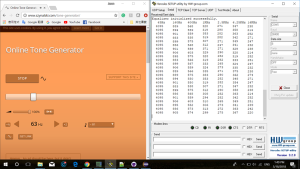
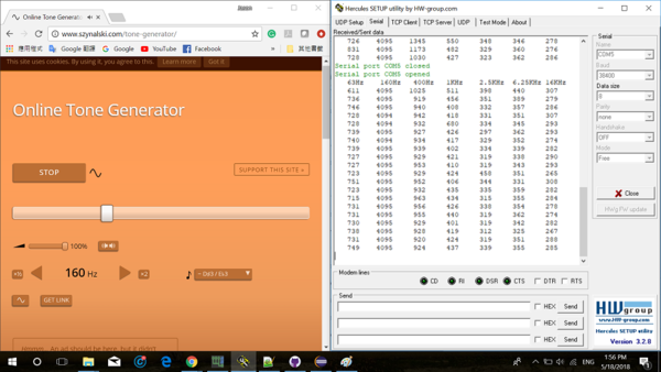
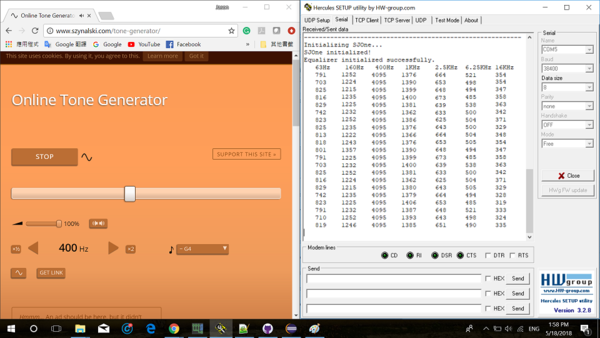
Because the MSGEQ7 chip is very sensitive to noise, we need to find out the lowest frequency it will read for every band. Even if there is no input, the MSGEQ7 chip can still read a small number of values. Hence, we use the Online Tone Generator website in Appendix section and have the equalizer connected to our laptop via AUX cable to test out every band's lowest frequency value, so we can implement the RGB LED matrix display properly.
Reading the ADC values
In order to read the ADC values properly, generating the strobe with precise timing is required. If the timing isn't precise, the whole date of the frequency values will be unreadable. The ADC values are read in the way in Software Design section, so we can get all seven bands values. correctly.
RGB LED Matrix Challenges
Testing
We test the RBG LED Matrix by creating a two-dimensional array to match up with all the LED on the matrix panel, so we can light up a specified LED and set with a specific color to it. To implement that, we need to follow the steps in Hardware Interface section, so the RGB LED matrix can be driven properly.
Matrix Array Controlling
The issue we had was trying to control one LED at a time in the matrix array. For example, following the pattern (row, column), the first LED index is (0, 0), and the last LED index is (15, 31). It didn't help that the LED matrix is split into two, meaning that row 0 and 8, 1 and 9,..... 7 and 15, were both enabled at the same time. The buffers had to be precisely enabled with a certain color at the same time the next clock cycle came.
Display Algorithm in LED Matrix
Creating a good algorithm to display properly took us a lot of time since we have a function which is using the acceleration sensor on SJOne board to rotate the entire RGB LED matrix display with all other functions, and it increases the difficulty to display. To display in general, this RGB LED matrix is designed in upper and lower panel which means whenever we try to light up an LED, we have to make sure that we are lighting up in the upper or the lower, and that is why we use two different set color functions that specific in top and bottom color set.
Color Variety
Due to the fact that the CPU clock speed of the SJOne board isn't fast enough to let us smoothly control the RGB pins other than GPIO, so we can only set the LED's color in seven different colors. But in return, with full light up speed, the display FPS is high enough to not let human eyes notice which make human thinks the LEDs is constantly lit up instead of flashing in a high frequency.
Conclusion
In conclusion, our project is an excellent bundle of an audio decoder, audio analyzer, and RGB LED matrix. We were able to finish our project, but ultimately we learned the most by putting our hands on creating this project. Different failures have taught us how important it is to test everything iteratively and carefully. Even integrate two different systems into one could be really hard to do, but with the right comments in code and good coding styles make it much more easy to do so. In addition, within doing this project, we had developed many skills like communication and time management in order to make everything work even though we are short on group members. Even this project is finished, we are still interested in improving it or adding more systems or functions into it because this project is no longer just as a project to us but something you can get a sense of accomplishment from.
Project Video
Project Source Code
- Audio Spectrum Analyzer with Graphics Display Source Code Link to Github
- File:CmpE244 S18 FRITOS Source Code.zip
References
Acknowledgement
We would like to appreciate Professor Preetpal Kang for the knowledge he provided us throughout the semester and gave us ideas of how to improve this project while it was just a proposal. With his ideas, this project was completed with a sense of accomplishment.
References Used
- VS1053 Datasheet
- MSGEQ7 Datasheet
- RGB LED Matrix Tutorial
- Amazon FreeRTOS API
- FreeRTOS API (original)
