Difference between revisions of "F15: Minion"
(→Hardware Design) |
(→Hardware Design) |
||
| Line 915: | Line 915: | ||
Below are the timing diagrams for the sensor | Below are the timing diagrams for the sensor | ||
| − | [[File:CMPE243_F15_Minion_Timing_Diagram_MB1010.jpg|left|600px|thumb|Timing Diagram for LV MaxSonar EZ Sensor]] [[File:CMPE243_F15_Minion_LV-EZ Ultrasonic Range Finder_200px.jpg| | + | [[File:CMPE243_F15_Minion_Timing_Diagram_MB1010.jpg|left|600px|thumb|Timing Diagram for LV MaxSonar EZ Sensor]] [[File:CMPE243_F15_Minion_LV-EZ Ultrasonic Range Finder_200px.jpg|right|200px|thumb|MB1010 Sensor]] |
Revision as of 20:02, 5 December 2015
Contents
- 1 Grading Criteria
- 2 Minion
- 3 Abstract
- 4 Objectives & Introduction
- 5 Schedule
- 6 Parts List & Cost
- 7 Design & Implementation
- 8 Testing
- 9 Technical Challenges
- 10 Conclusion
- 11 References
Grading Criteria
- How well is Software & Hardware Design described?
- How well can this report be used to reproduce this project?
- Code Quality
- Overall Report Quality:
- Software Block Diagrams
- Hardware Block Diagrams
- Schematic Quality
- Quality of technical challenges and solutions adopted.
Minion
Abstract
This section should be a couple lines to describe what your project does.
Objectives & Introduction
Show list of your objectives. This section includes the high level details of your project. You can write about the various sensors or peripherals you used to get your project completed.
Team Members & Responsibilities
Sensor Controller:-
Motor & I/0 Controller:-
Communication Bridge & Android Controller:-
- Akshay Kanchar
- Asmita Deshpande
Geographical Controller:-
- Amit Pachore
- Sindhuja Gopalakrishnan Elango
Master Controller:-
- Gaurao Chaudhari
- Akshay Dabholkar
Tester:-
Treasurer:-
- Keerthanaa Alagudurai
Hardware:-
- Amit Pachore
- Gaurao Chaudhari
- Bhupendra Naphade
Release:-
- Akshay Kanchar
Schedule
Common Schedule
| Sl. No | Start Date | End Date | Task | Status | Actual Completion Date |
|---|---|---|---|---|---|
| 1 | 9/22/2015 | 9/28/2015 | RC Car and important component buying | ||
| 2 | 9/29/2015 | 10/6/2015 | 1) Algorithm and architecture 2) Setup of car and decision on CAN Id's |
||
| 3 | 10/7/2015 | 10/13/2015 | 1) Coding and final set-up of car 2) Successful communication of CAN bus. 3) Car in running position. |
||
| 4 | 10/14/2015 | 10/20/2015 | Sensor Data gathering and movement according to sensors. | ||
| 5 | 10/21/2015 | 10/27/2015 | 1) LCD Display working and finalizing the data to be displayed on LCD module. 2) GEO data gathering and controlling of car using Android module. |
||
| 6 | 10/28/2015 | 11/3/2015 | Integration of all the modules into one. | ||
| 7 | 11/4/2015 | 11/10/2015 | Inclusion of new features in the car. | ||
| 8 | 11/11/2015 | 11/17/2015 | Testing depending upon the newly added features. | ||
| 9 | 11/18/2015 | 11/24/2015 | Testing of Car and testing the self driving capability | ||
| 10 | 11/25/2015 | 12/1/2015 | Testing of Car |
Sensor Controller Schedule
| Sl. No | Start Date | End Date | Task | Status | Actual Completion Date |
|---|---|---|---|---|---|
| 1 | 9/20/2015 | 10/5/2015 | Study available sensors and place order | Completed | 10/4/2015 |
| 2 | 10/6/2015 | 10/13/2015 | Collaborate with the other sub teams to finish the CAN bus communication | Completed | 10/13/2015 |
| 3 | 10/13/2015 | 10/20/2015 | Develop simple test code for the sensors | Completed | 10/18/2015 |
| 4 | 10/21/2015 | 10/30/2015 | Interface all sensors and develop code for reading all sensors. | Completed | 10/30/2015 |
| 5 | 10/30/2015 | 11/2/2015 | Positioning of sensors and identifying dead band if any | Completed | 11/2/2015 |
| 6 | 11/2/2015 | 11/5/2015 | Work on light and battery sensor (optional) | ||
| 7 | 11/06/2015 | 12/17/2015 | Final testing and debugging |
Motor & I/0 Controller Schedule
| Sl. No | Start Date | End Date | Task | Status | Actual Completion Date |
|---|---|---|---|---|---|
| 1 | 9/21/2015 | 9/25/2015 | Order LCD Display | Completed | 9/25/2015 |
| 2 | 9/28/2015 | 10/3/2015 | Going through the motor concepts and PWM | Completed | 10/2/2015 |
| 3 | 10/4/2015 | 10/9/2015 | Intreface the DC and SERVO Motors with SJONE board | Completed | 10/8/2015 |
| 4 | 10/10/2015 | 10/13/2015 | Establishing basic CAN communication with other modules | Completed | 10/13/2015 |
| 5 | 10/11/2015 | 10/16/2015 | Getting the car to run with the PWM signals from Motor controller | Completed | 10/15/2015 |
| 6 | 10/17/2015 | 10/23/2015 | Research on Speed cotrol method and sensor for the same interface LCD display with LPC1758 via UART | Completed | 10/21/2015 |
| 7 | 10/23/2015 | 11/4/2015 | Establishing reliable CAN communication for IO & Motor with others | Completed | 11/4/2015 |
| 8 | 11/5/2015 | 11/12/2015 | Integrate Speed sensor and get feedback. Start working on start,stop buttons and headlight | Completed | 11/11/2015 |
| 9 | 11/13/2015 | 11/20/2015 | Testing substantial self driving capability of the car | ||
| 10 | 11/21/2015 | 11/30/2015 | Complete integration, Debugging and Fine tuning | ||
| 11 | 12/1/2015 | 12/5/2015 | Final Validation |
Geographical Controller Schedule
| Sl. No | Start Date | End Date | Task | Status | Actual Completion Date |
|---|---|---|---|---|---|
| 1 | 09/27/2015 | 10/07/2015 | Ordering Parts and understanding each module | Completed | 10/11/2015 |
| 2 | 10/07/2015 | 10/13/2015 | CAN Communication with other boards and understanding each module | Completed | 10/13/2015 |
| 3 | 10/07/2015 | 10/30/2015 | Algorithm for distance and heading calculation and coding | Completed | 10/30/2015 |
| 4 | 10/14/2015 | 10/20/2015 | Interfacing of compass(I2C) and GPS (UART) with SJONE board | Completed | 10/20/2015 |
| 5 | 10/20/2015 | 10/30/2015 | Coding, Compass Calibration,GPS Calibration | Completed | |
| 5 | 10/25/2015 | 11/15/2015 | Individual unit testing | Completed | |
| 6 | 10/30/2015 | 11/30/2015 | Interfacing with Android, Master and IO controllers | ||
| 7 | 10/30/2015 | 11/30/2015 | Integration Testing,On Car Calibration | First level of On Car Calibration Completed |
Master Controller Schedule
| Sl. No | Start Date | End Date | Task | Status | Actual Completion Date |
|---|---|---|---|---|---|
| 1 | 09/30/2015 | 10/6/2015 | a) Design of Algorithm and Architecture for Master Module. b) Setup of CAN communication between two controllers. |
Completed | 10/6/2015 |
| 2 | 10/7/2015 | 10/13/2015 | a) Development of CAN message system for Android, Sensor and GPS, I/O reception. b) Decide about periodic function frequencies that’ll be handling different modules. |
Completed | 10/13/2015 |
| 3 | 10/14/2015 | 10/20/2015 | a) Development of driving,stopping and obstruction avoidance algorithm for motor. b) Implementation of LED Display to display number of messages on CAN bus. c) Implementation of turning algorithm as per the data received from the Geo Controller. |
Completed | 10/20/2015 |
| 4 | 10/21/2015 | 10/27/2015 | a) Designing of Kill switch with the help of Motor, I/O and Android. b) Design the system to restore the last known configuration. c) Implementation to reset modules if the CAN bus reaches BUS off state. |
Completed | 10/27/2015 |
| 5 | 10/28/2015 | 11/3/2015 | a) Design of Head Light functionality with the help of Sensor module. b) Implementation of log files saving to SD card. |
||
| 6 | 11/4/2015 | 11/10/2015 | a) Integration of all the modules with Master module and check it after combining everything. b) Probable implementation of additional features. |
||
| 7 | 11/11/2015 | 11/17/2015 | a) Refine the work done earlier.Change areas that need a change. b) Test the Master module while all the modules are integrated together and list down modifications and additions to be done. |
||
| 8 | 11/18/2015 | 11/24/2015 | Testing of system and specially making sure that last week’s shortcomings are taken care of. | ||
| 9 | 11/25/2015 | 12/1/2015 | a) Final testing of individual modules. b) Testing the self-driving capability of the car. |
||
| 10 | 12/2/2015 | 12/8/2015 | Final working on the shortcomings in the previous week. | ||
| 11 | 12/9/2015 | 12/15/2015 | Final Testing of Car. |
Communication Bridge & Android Controller Schedule
| Sl. No | Start Date | End Date | Task | Status | Actual Completion Date |
|---|---|---|---|---|---|
| 1 | 9/29/2015 | 10/06/2015 | Ordering bluetooth module and setting up android dev enviornment | Completed | 10/06/2015 |
| 2 | 10/06/2015 | 10/13/2015 | Implementing basic UI with Start and Stop buttons and testing bluetooth module | Completed | 10/12/2015 |
| 3 | 10/13/2015 | 10/27/2015 | Integrating android app with bluetooth module and SJ One board | Completed | 11/01/2015 |
| 4 | 10/27/2015 | 11/03/2015 | Establishing communication with other modules using CAN and testing Prototype | Completed | 11/07/2015 |
| 5 | 11/03/2015 | 11/17/2015 | Enhancing UI features with Google Maps and display of sensor data from different modules | Ongoing | |
| 6 | 11/17/2015 | 12/01/2015 | Setting up Communication with GPS and Master and prototype testing | ||
| 7 | 12/01/2015 | 12/08/2015 | Final app testing |
Parts List & Cost
Give a simple list of the cost of your project broken down by components. Do not write long stories here.
Design & Implementation
CAN Communication Table
| Sr. No | Message ID | Message function | Message Data | From | To |
|---|---|---|---|---|---|
| High | |||||
| 1 | 0x220 | Motor Control (Direction Control- Straight, Left or Right Level of Direction-Level 0, Level1, Level 2 Motion Control- Stop, Forward or Reverse Speed Control - Stop, Level1, Level2 or Level3) |
Byte[0] -> Direction Control Byte[1] -> Level of Direction Byte[2] -> Motion Control Byte[3] -> Speed Control |
Master | Motor |
| 2 | 0x010 | Kill Message (User request to stop the car under emergency) |
Control Frame. No data bytes. | Android | Master |
| 3 | 0x020 | Kill Message (Master request to stop all controllers and reboot under emergency) |
Control Frame. No data bytes. | Master | All |
| 4 | 0x030 | Stop (User request to stop the car) |
Control Frame. No data bytes. | Android | Master |
| 5 | 0x040 | Stop (Master stops the motor) |
Control Frame. No data bytes. | Master | Motor |
| 6 | 0x210 | Sensor Data (Distance in cms) |
Byte[0] -> Forward Distance Byte[1] -> Left Distance Byte[2] -> Right Distance Byte[3] -> Back Distance |
Sensor | Master/Motor-IO |
| 7 | 0x230 | Total Distance to Travel | Byte[0-1] | Android | Geo |
| 8 | 0x240 | Send Checkpoints | Byte[0-3] -> Latitude Byte[4-7] -> Longitude |
Android | Geo |
| 9 | 0x250 | Distance (Distance in foot) |
Byte[0-1] -> Final Distance remaining Byte[2-3] -> Checkpoint distance |
Geo | Master |
| 10 | 0x260 | Turn Angle and Direction | Byte[0] -> Turn Angle Byte[1] -> Direction (1-Left,2-Right) |
Geo | Master |
| 11 | 0x270 | Run and Pause Command | Control Frame. No data bytes | Android | Master |
| 12 | 0x280 | Heartbeat Message | Control Frame. No data bytes | Motor | Master |
| 13 | 0x281 | Heartbeat Message | Control Frame. No data bytes | Geo | Master |
| 14 | 0x282 | Heartbeat Message | Control Frame. No data bytes | Android | Master |
| 15 | 0x283 | Heartbeat Message | Control Frame. No data bytes | Sensor | Master |
| Medium | |||||
| 16 | 0x410 | Destination reached. (Stops the car when destination is reached) |
Control Frame. No data bytes | Master | All |
| 17 | 0x420 | Battery Status | Byte[0-1] | Sensor | Master/IO |
| Low | |||||
| 18 | 0x610 | Boot Request | Control Frame. No data bytes | Master | All |
| 19 | 0x620 | Boot Reply (Date and time will be sent to Master) |
Byte[0-4] | Motor-IO | Master |
| 20 | 0x621 | Boot Reply (Date and time will be sent to Master) |
Byte[0-4] | Sensor | Master |
| 21 | 0x622 | Boot Reply (Date and time will be sent to Master) |
Byte[0-4] | Geo | Master |
| 22 | 0x623 | Boot Reply (Date and time will be sent to Master) |
Byte[0-4] | Android | Master |
| 23 | 0x630 | Boot Status (Enable the map and run button in Android) |
Control Frame. No data bytes | Master | Motor-IO/Android |
| 24 | 0x640 | System Start | Control Frame. No data bytes | Android | All |
| 25 | 0x650 | Source Co-ordinates | Byte[0-3] -> Source Latitude Byte[4-7] -> Source Longitude |
Geo | Android |
Car Framework and Components
The RC car, Traxxas Stampede, in its raw form consists of a Titan 12T 550 Brushed DC motor, a Servo motor, an XL-5 ESC (Electronic Speed Control) unit, battery and a pre-programmed wireless receiver and controller. The Battery used in the RC car is an 8.4 V, 3000 NiMH from Traxxas. The wireless receiver gets commands from the remote control and drives the motors accordingly, but the DC motor can be controlled only through ESC.
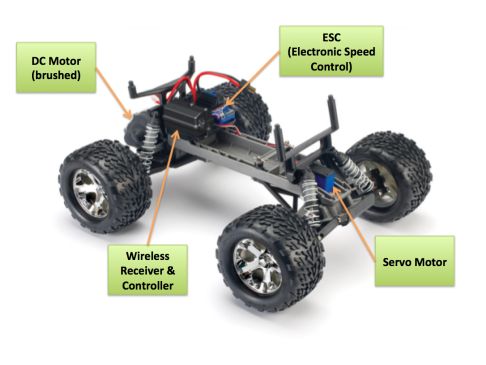

The ESC (Electronic Speed Control) unit is an electronic module, which receives PWM signals from the controller and varies speed and direction of the DC motor and also acts as dynamic brakes. ESCs are often used in RC models. The ESC has the capability to provide dynamic braking depending on the mode in which it is being operated.
Motor and I/O Controller
Hardware Design
Motor Module
The motor module comprises of a servo motor for the direction control and a DC motor for speed control. The servo motor helps the car in turning left and right where as the DC motor on the other hand helps the car move forward and backward. The motor used in the project is a brushed motor. Conventionally, brushless motors are faster and more efficient than brushed motors. But, the reason for selecting a brushed motor over a brushless motor is that we employ a dedicated battery for the motor such that we do not have any issues with power and efficiency. Moreover, we need not operate the car at high speeds.
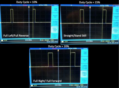
The initial task in the motor module is to find the operating ranges of the motor so that we get to know the output signal range and frequency from the SJONE board which would be replacing the pre-programmed controller. The simplest way to find the operating ranges of the motor is to tap and analyze PWM signal that is being supplied to the motor over an oscilloscope. The results as shown in the below pictures indicate that the operating duty cycle of both the motors lie between 10% to 20% and the frequencies at which the motors operate is 100Hz.

IO Module
The IO module Consists of a 4 line * 20 characters serial LCD. Data from GPS and sensor module is displayed continuously by refreshing it every second. SJ one board communicates with LCD through UART. GPS data :-
- Latitude
- Longitude
- Final distance remaining
Sensor data:-
- Left sensor reading
- Right sensor reading
- Front sensor reading
- Rear sensor reading
Additionally, IO module controls lighting up headlights/taillights based on the direction of the car movement.
Hardware Interface
LCD unit requires 5V power supply for its working. The VCC and Ground pins are connected to common power supply lines that is used to power up all the boards. The Rx pin of LCD is connected to TXD2 (p2.8) pin on SJ one board. Two of the GPIO pins p2.6 and p2.7 controls the headlights LED’S and taillights LED’S respectively.
| Sl. No | Pin on IO Module | Pin on SJSU One Board | Purpose |
|---|---|---|---|
| 1 | Vcc | Common power supply | 5V for LCD |
| 2 | Ground | Common Ground | Ground for LCD |
| 3 | Rx | P2.8(TXD2) | Receive data from SJone board through UART |
| 4 | Headlight LED’s(2) | P2.6 | Turn on headlights when car is moving in the forward direction |
| 5 | Taillight LED’s (2) | P2.7 | Turn on tail-lights when car is moving in the reverse direction |
Software Design
IO Module
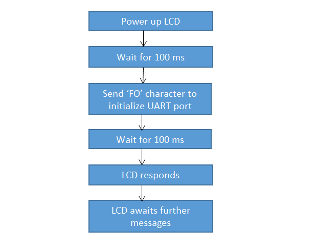
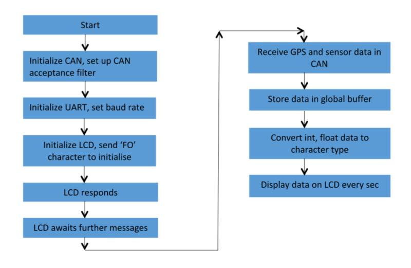
LCD communicates with SJ one board through UART. The UART port is configured to operate at the default baud rate of 9600 bps. “FO” character is sent to initialize the UART port after a delay of 100 ms, upon powering up the board. The display unit responds after 100 ms. Now the LCD module is configured and can receive further messages to display on it. Data from modules such as GPS and sensor are received continuously through CAN. It is decoded, converted into proper format and displayed on the LCD periodically.

Implementation
“Can receive” function is called in periodic scheduler 100 Hz task. This function lets the Motor/IO module receive CAN messages from other modules connected to it. CAN set up filter function has been used to accept only essential messages required by this module. Based on the CAN message identifier, corresponding action is performed. These are the CAN messages required by the motor/IO module.
CAN MESSAGE ID:-
- 0x210 – Sensor data
- 0x220 – motor control message from master
- 0x240 , 0x250 – GPS data
Data from sensor and GPS modules are stored in global message buffers. Sensor data is 8 bit whereas GPS data ranges between 16-32 bits. These integer values are converted into character type and then sent to LCD through UART.
LCD display function is called in 1Hz periodic scheduler task. Thus Sensor and GPS data get displayed on the LCD every sec.

Master Controller
As the name suggests, it is main controller on the car which interacts with all other controllers over the CAN Bus to achieve real-time functionality. Basic function of the Master Controller is to receive data from Android, Geo and Sensor Modules and develop the algorithm to drive the car autonomously based on the received data through the Motor Controller.
Hardware Design
- RC car was the basic infrastructure that was required to implement the project.
- CAN Bus with five SJone controller boards was integrated on General purpose Printed Circuit Board (PCB).
- Sufficient power-supply ports and external pins were provided to each controllers.
- Flat Ribbon Cables were used to reduce circuit complexity arising from external connecting wires.
Software Design
- Master Controller uses FreeRTOS environment to achieve its functionality.
- It uses Periodic Scheduler Task provided by Preet at its core to communicate with all other controllers.
- The functions of the Periodic Scheduler Task were used in a customized manner to transmit/receive the messages at specific intervals of 1Hz,10Hz,100Hz and 1000Hz.
- File logger function was used to log the real-time data onto SD card which was used for debugging purpose.
- Can Message structure of 11-bit id was implemented to send and receive CAN messages over the CAN Bus.
- CAN acceptance filter was set-up to receive messages specific to Master Controller from the CAN Bus, since it is the broadcast Bus.
Software Implementation
- Master Controller starts with initialization of CAN Bus and setting up reception filter from the main() function.
- The Periodic Scheduler Task then takes over to implement the actual functionality of the Master Controller.
- CAN_is_busoff() was used at an interval of 10Hz through periodic scheduler task to check if CAN bus was working continuously.
- The basic flow of control is as follows:
Sensor Controller
Sensor controller consists of sonar and ultrasonic sensors that are inter-connected to the SJOne board and CAN bus. The sensors detect if there is any obstacle around the car and report the distance of obstacle.
Hardware Design
Hardware design consists of four sensors connected to ports of LPC1758. The sensors in front, right and left direction are MB1010 sensors while the one at back is HCSR04. The sensors are connected to +5V to achieve the highest beam pattern that is available. The LV MaxSonar EZ detects objects from 0 inches to 254 inches and provides sonar range from 6 to 254 inches with 1 inch resolution. Objects from 0 to 6 inches are reported as 6 inches. Sensor operates at 42KHz. The sensor reports output formats in from of pulse width output, analog voltage output, and RS232 serial output. We have selected pulse width output.The sensor will continually measure range and output if RX data is left unconnected or held high. If held low the sensor will stop ranging. We have commanded a range reading by triggering high for 20uS. Below are the timing diagrams for the sensor


It Requires 5V 15mA power supply. When a short 10uS pulse is provided to the trigger input, the sensor will transmit out 8 cycle of ultrasonic burst at 40kHz and makes the echo pin high. The Echo pin is lowered to logic low when the ultrasound burst is reflected off a distant object. To obtain the distance, measure the width (Ton) of Echo pin.
Time = Width of Echo pulse, in uS (micro second) Distance in centimeters = Time / 58 Distance in inches = Time / 148 Or you can utilize the speed of sound, which is 340m/s

Software Design
Geographical Controller
Geographical Controller consists of GPS and Compass module. GPS module is used to track current position of car, find bearing angle of destination with respect to north and compass module used to know heading of car with respect to north. Difference between heading and bearing gives us turn angle which car have to take to reach destination from current position.
Hardware Design
Schematic

SparkFun Venus GPS with SMA Connector
SparkFun Venus GPS uses Skytraq VENUS634FLPx IC. The Venus638FLPx outputs standard NMEA-0183 or SkyTraq Binary sentences at a default rate of 9600 bps which is adjustable to 115200 bps, with update rates up to 20Hz. We configured this module with update rate of 10Hz and 38400 bps UART rate. Module outputs GGA, GSA, GSV, GLL, RMC, VTG, ZDA NMEA standard messages which can be configures to as per our requirements. We configured it to give only GGA messages.
GGA message format is shown below.
For configuring GPS modules to UART rate 38400 bps, 10Hz update rate and only GGA message at output, below binary commands are used.


HMC5883L

Software Design
The GPS communicates with the SJOne board through the UART and the Compass communicates with the SJOne board through the I2C
I2C Communication
The HMC5883L IC communicates to the SJOne Board through the I2C bus.
SJONE board -Master device
HMC5883L - Slave device
The I2C rate is controlled by the master and can be upto maximum 400 KHz. We have configured the rate as 100 KHz.
Master Transmitter Mode:
In this mode, the master writes to the slave registers.
The compass IC has a set of 8 bit registers to be initially configured for parameters such as device output rate, number of samples, device gain and operating mode. By identifying the device write address and register address, the values can be written by the SJONE board to the compass registers.
Master Receive Mode:
In this mode, the master reads from the slave registers.
The X,Y,Z registers of the compass can be then read by the SJOne board one by one knowing the device read address and register address.The register pointer will be incremented by 1 automatically after the current register has been successfully read.
Android Communication Bridge Controller
Hardware Design
The Communication bridge consists of establishing connection between car and the android phone which is established with the help of bluetooth module HC-05 connected to UART peripheral of SJOne Board. The UART pins on board are connected to bluetooth module in the manner shown in diagram. Once the connection is established between the car and the android phone and signals like 'Start','Stop' and 'Kill' are sent from android phone then they are received by the bluetooth and sent to SJOne board to be further broadcasted over CAN bus.


Software Design
Android Application
Software Design
Testing
Describe the challenges of your project. What advise would you give yourself or someone else if your project can be started from scratch again? Make a smooth transition to testing section and described what it took to test your project.
Accuracy of GPS Module

Accuracy of GPS module was tested by recording/logging coordinates received by module using LOG_INFO() function and plotting them on Google maps GPS Module Coordinates on Google Maps. GPS module was very much accurate we did not needed to calibrate it. It is observed that more number of satellite locks with module, greater the accuracy of coordinate readings.
Calibration of Compass
As any instrument has instrument error, so has the compass IC. The compass needs to be calibrated for accuracy. We undertook two levels of calibration.
1. Level 1 calibration was done without mounting the compass on car. The compass was rotated in its axis for 360 degrees and the error was identified for every 15 degrees (totally 24 zones) with the setup shown by the image in the left.
2. Level 2 calibration was done after mounting the compass on car.The car setup by itself had some tilt and we compensated it by means of adjusting the hardware mounting. Next, the motor’s EMI caused some magnetic deviation and the motor's influence was taken into account too. The car was rotated in its axis ( its axis being parallel to the compass axis) for 360 degrees with the deviation measured for every 15 degrees(totally 24 zones) with the setup depicted by the image in the right.


The deviation was not uniform for every zone. Using linear regression analysis technique, the relationship between the predictor variable - degrees and the response variable - radians was found in an ideal environment and the same was repeated several times for accuracy. The average of several such readings was taken as the final calibration value.


Technical Challenges
Configuring GPS Module
We faced difficulty in configuring GPS module to sending only $GGA messages, 10Hz Position update rate and updating baud rate to 38400. Initially we were trying to configure GPS module via writing program for SJ One board and we were unable to do it. Later on we completed configuring by connecting GPS module directly to serial port and using GPS Viewer software. Through it we can directly configure GPS module without worrying about binary messages and checksum calculation.
Compass and Calibration
1. Initially the compass was mounted and tested on breadboard with its upper face downwards as the connecting strips are on the upper side. This made the compass produce incorrect values.
2. While reading the registers in compass HMC5883L, only x and y register values are needed. Hence we tried to read only those registers from the device. But it so happened that z register is in between the x and y registers and the read pointer did not advance after the x register was read and remained in the z register. This led to compass producing constant values.
3. While calibrating, the compass should be rotated on a horizontal plane with its axis of rotation fixed. Shifting the axis may result in incorrect values.
4. Having a robust hardware that does not cause any or very less tilt, will reduce the efforts of calibration as HMC5883L IC is not tilt compensated.
5. Calibration should be done in an environment which does not have iron , magnetic particles etc as those may cause magnetic deviation. As the motor module influences the compass with the generated EMI, mount the compass far away from the motor and calibrate with the motor ON to take account of the EMI generated.
Conclusion
Conclude your project here. You can recap your testing and problems. You should address the "so what" part here to indicate what you ultimately learnt from this project. How has this project increased your knowledge?
Project Video
Upload a video of your project and post the link here.
Project Source Code
References
Acknowledgement
Any acknowledgement that you may wish to provide can be included here.
References Used
Appendix
You can list the references you used.